1
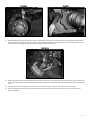
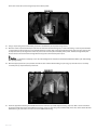
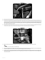
Figure 38
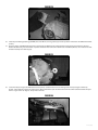
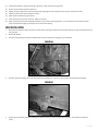
64. Position the provided CV spacer (02328 - Standard, 02329 - Narrow Track) between the CV shaft and the differential mounting flange (Fig
39). Fasten the CV and spacer to the differential flange with 10mm x 70mm socket head cap screws for standard track systems. Use 10mm
x 50mm bolts and 10mm washers for narrow track systems. (BP 568 - Standard, 578 - Narrow Track). Use Loctite on the bolt threads and
torque to 45 ft-lbs using a crossing pattern.
Figure 39
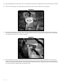
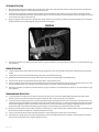
65. Standard Knuckle Kits Only: Reconnect the brake hose bracket to the upper control arms with the original bolt. Torque to 10 ft-lbs. Attach
the second brake hose bracket to the holes in the back side of the steering knuckle with a provided 1/4” x 3/4” bolt and washer (BP 572).
Torque to 10 ft-lbs (Fig 40A).
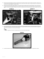
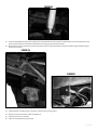
66. Standard Knuckle Kits Only: Route the ABS line from around the back side of the knuckle and attach to the two threaded holes with the
provided wire clamps and 1/4” x 3/4” bolts and washers (BP 572). From there run the ABS line up along the brake line to the frame and
reconnect to the connector and plastic retaining clip. Zip tie the ABS line to the brake line (Fig 40B).
FigURE 40A
FigURE 40B
021663 | 21