1
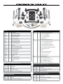
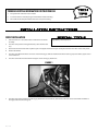
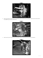
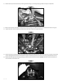
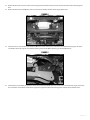
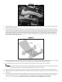
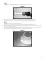
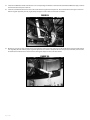
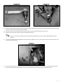
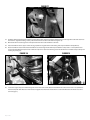
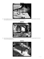
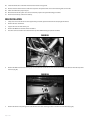
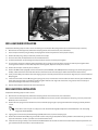
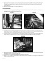
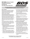
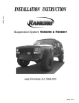
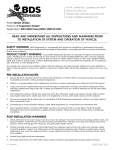
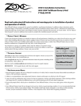
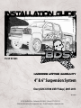
Part#: 021643
4” & 6” Suspension System
Chevy/GMC K1500 2WD Pickup | 2007-2013
Rev. 092713
491 W. Garfield Ave., Coldwater, MI 49036 . Phone: 517-279-2135
Web/live chat: www.bds-suspension.com . E-mail: [email protected]
Read And Understand All Instructions
And Warnings Prior To Installation Of
System And Operation Of Vehicle.
Your truck is about to be fitted with the best suspension system on the market today. That means you will be driving the
baddest looking truck in the neighborhood, and you’ll have the warranty to ensure that it stays that way for years to come.
Thank you for choosing BDS Suspension!
BEFORE YOU START
BDS Suspension Co. recommends this system be installed by a professional
technician. In addition to these instructions, professional knowledge of
disassembly/ reassembly procedures and post installation checks must be
known.
FOR YOUR SAFETY
Certain BDS Suspension products are intended to improve off-road performance. Modifying your vehicle for off-road use may result in the vehicle
handling differently than a factory equipped vehicle. Extreme care must
be used to prevent loss of control or vehicle rollover. Failure to drive your
modified vehicle safely may result in serious injury or death. BDS Suspension
Co. does not recommend the combined use of suspension lifts, body lifts, or
other lifting devices. You should never operate your modified vehicle under
the influence of alcohol or drugs. Always drive your modified vehicle at reduced speeds to ensure your ability to control your vehicle under all driving
conditions. Always wear your seat belt.
BEFORE INSTALLATION
Special literature required: OE Service Manual for model/year of vehicle.
Refer to manual for proper disassembly/reassembly procedures of OE and
related components.
Adhere to recommendations when replacement fasteners, retainers and
keepers are called out in the OE manual.
Larger rim and tire combinations may increase leverage on suspension,
steering, and related components. When selecting combinations larger
than OE, consider the additional stress you could be inducing on the OE and
related components.
Post suspension system vehicles may experience drive line vibrations.
Angles may require tuning, slider on shaft may require replacement, shafts
may need to be lengthened or trued, and U-joints may need to be replaced.
Secure and properly block vehicle prior to installation of BDS Suspension
components. Always wear safety glasses when using power tools.
Visit 560plus.com for more information.
In an effort to reduce the risk of rollover crashes the National
Highway Traffic Safety Administration (NHTSA) established the
Federal Motor Vehicle Safety Standard (FMVSS) No. 126 requiring all new passenger vehicles under 10,000
lbs GVWR include an electronic stability
control (ESC) system as standard equipment.
Effective August 2012 this law requires aftermarket products to be compliant with these
same standards.
FITMENT GUIDE
4” Lift:
33x12.50 on 17x9 w/ 5” backspacing
33x12.50 on 20x9 w/ 5.75” backspacing
6” Lift:
35x12.50 on 17x9 w/ 5” backspacing
35x12.50 on 20x9 w/ 5.75” backspacing
If installation is to be performed without a hoist, BDS Suspension Co. recommends rear alterations first.
Due to payload options and initial ride height variances, the amount of lift
is a base figure. Final ride height dimensions may vary in accordance to
original vehicle attitude. Always measure the attitude prior to beginning
installation.
BEFORE YOU DRIVE
Check all fasteners for proper torque. Check to ensure for adequate clearance between all rotating, mobile, fixed, and heated members. Verify clearance between exhaust and brake lines, fuel lines, fuel tank, floor boards and
wiring harness. Check steering gear for clearance. Test and inspect brake
system.
2 | 021643
Perform steering sweep to ensure front brake hoses have adequate slack and
do not contact any rotating, mobile or heated members. Inspect rear brake
hoses at full extension for adequate slack. Failure to perform hose check/
replacement may result in component failure. Longer replacement hoses, if
needed can be purchased from a local parts supplier.
Perform head light check and adjustment.
Re-torque all fasteners after 500 miles. Always inspect fasteners and components during routine servicing.
021643
021643
Part #
Qty
Description
02160
1
621
1
Bolt Pack (x-member hardware)
Steering Knuckle (drv)
2
5/8"-11 x 4-1/2" bolt grade 8
5/8"-11 x 5-1/2" bolt grade 8
02161
1
Steering Knuckle (pass)
2
02176
1
Front Crossmember
4
5/8"-11 prevailing torque nut
8
5/8" SAE flat washer
1
Bolt Pack (front new bolt pack)
02177
1
Rear Crossmember
02166
2
Sway Bar Drop Bracket
98161
1
Front Strut Kit (6" Kit)
4
1/2"-13 x 1-1/4" bolt grade 8 yellow zinc
3
1/2"-13 x 3" bolt grade 8 yellow zinc
5
1/2"-13 prevailing torque nut yellow zinc
12
1/2" SAE washer thru-hardened yellow zinc
4
10mm-1.50 x 130mm bolt class 10.9 clear zinc
4
10mm flat washer clear zinc
4
Wire Clip
2
1/4"-20 x 3/4" bolt grade 5 clear zinc
2
1/4" split lock washer clear zinc
2
1/4" SAE washer clear zinc
1
Bolt Pack (rear kit)
1
5/16" x 1 bolt grade 5 clear zinc
641
98141
1
Front Strut Kit (4" Kit)
02185
1
Belly Pan
02115
1
Brake Line Relocation (Drv)
02116
1
Brake Line Relocation (Pass)
B56.75G2
2
5/16"-18 x 3/4" bolt
N56SS
2
5/16"-18 hex nut
LW56
2
5/16" lock washer
W56SAE
2
5/16" flat washer
099000
7
Zip Ties
3396
2
Bump Stop Extension
SBLA
1
Brake Line Extension
1
5/16"-18 prevailing torque nut clear zinc
342701
1
Loctite
2
5/16" SAE flat washer clear zinc
2
10mm-1.50 x 110mm Allen head bolt
011559 Rear Kit - Block and Add-A-Leaf
Part #
Qty
Description
111209
2
Add-A-Leaf
069409
2
4" Block
228003
1
3/8" Center Pin Kit
040038
4
9/16" x 2-1/2" x 14" U-bolt Kit
628
011458 Rear Kit - Replacement Spring
Part #
Qty
Description
001559
2
Rear Spring
040036
4
9/16" x 2-1/2" x 8-3/4" U-bolt Kit
071007
2
Spring Bushing Kit
011558 Rear Kit - Replacement Spring
011457 - Rear Kit - Block
Part #
Qty
Description
Part #
Qty
Description
001559
2
Rear Spring
BB088
2
5" Block
040037
4
9/16" x 2-1/2" x 10" U-bolt Kit
040038
4
9/16" x 2-1/2" x 14" U-bolt Kit
071007
2
Spring Bushing Kit
021643 | 3
tROUBLESHOOTING INFORMATION FOR YOUR VEHICLE
1.
This system will not fit 2007 classic models
2.
20” wheels with 5-3/4” backspacing recommended to reduce trimming.
3.
Will not fit two-mode hybrid models with electronic power steering.
FRONT INSTALLATION
1.
Park the vehicle on a clean, flat surface and block the rear wheels
for safety.
2.
Disconnect the positive and negative battery cables from the battery.
3.
Raise the front of the vehicle with a hydraulic jack and support the frame with jack stands just behind the rear lower control arm pocket.
4.
Remove the wheels.
5.
Disconnect the ABS line from the connector on the frame (Fig 1). Remove the ABS line from the retaining clips at the frame, upper control
arm and knuckle.
6.
Disconnect the brake line bracket from the upper control arm (Fig 1). Retain bolt.
High Quality Strut Compressor
FigURE 1
7.
Disconnect the steering from the knuckle (Fig 2). Remove the tie rod end nut. Strike the knuckle near the tie rod end with a hammer to
dislodge it. Retain the mounting nut.
4 | 021643
FigURE 2
8.
Remove the two brake caliper mount bolts and remove the caliper assembly from the knuckle (Fig 3). Hang the caliper securely out of the
way. DO NOT hang the caliper by the brake hose.
FigURE 3
9.
Remove the sway bar links from the sway bar and the lower control arm (Fig 4). Retain the links, bushings and hardware.
FIGURE 4
021643 | 5
10. Remove the sway bar from the frame by removing the four bushing cap mounting bolts (Fig 5). Retain all sway bar components.
FIGURE 5
11. Mark each of the front strut bodies to indicate driver’s verses passenger’s side. Make the marks on the side of the strut that is facing out.
12. Support the lower control arm with a jack. Remove the lower strut mount bolts (Fig 6). Retain bolts.
FIGURE 6
13. Remove the upper and lower ball joint nuts and thread back on by hand a couple of turns. Strike the knuckle near the upper and lower ball
joints to dislodge them from the knuckle. Remove the upper and lower ball joint nuts and remove the steering knuckle from the vehicle.
14. Remove the three upper strut mounting nuts (Fig 7) and remove the strut from the vehicle. DO NOT remove the center strut rod nut, it is
under extreme pressure. Retain nuts.
FIGURE 7
6 | 021643
15. Remove the front and rear lower control arm mounting bolts and remove the lower control arm from the vehicle. Retain mounting hardware.
16. Remove the four bolts and the OE rear control arm pocket crossmember from the vehicle (Fig 8). Retain bolts.
FIGURE 8
17. Install the new rear crossmember (02177) with the OE lower control arm bolts, nuts and washers. Also fasten the passenger’s side of the
crossmember to the two original crossmember mounting holes with the OE hardware (Fig 9). Leave hardware loose.
FIGURE 9
18. Install the front crossmember (02176) in the control arm pockets with the OE lower control arm bolts, nuts and washers (Fig 10). Also fasten
the center of the crossmember to the frame using the two original front skid plate mounting holes and bolts. Leave hardware loose.
021643 | 7
FIGURE 10
19. Install the OE lower control arms in the new crossmembers and fasten with 5/8” x 4-1/2” and 5/8” x 5-1/2” bolts, nuts and 5/8” SAE washers
(BP 621). Leave hardware loose.
20. Loosely attach the new belly pan (02186) to the rear crossmember with three ½” x 3” bolts, nuts and ½” SAE washers (BP 641). If installing
the optional front skid plate (BDS #121613), loosely attach the new skid plate to the original upper skid plate mounting crossmember with
the factory skid plate hardware. Swing the front edge of the belly pan up to the front crossmember followed by the rear edge of the skid
plate (when applicable). Fasten the belly pan/skid plate to the front crossmember with ½” x 1-1/4” bolts and ½” SAE washers (BP 641) in
the two middle mounting holes (Fig 11). Use the same bolts and washers along with ½” nuts (BP 641) to fasten the plate in the two outer
mounting holes. Leave all hardware loose.
FIGURE 11
21. With the crossmembers, control arms and skid plate(s) installed, go back and torque the crossmember mounting bolts to 125 ft-lbs. Torque
all ½” skid plate hardware to 65 ft-lbs. If installing a 121613 skid plate, torque the upper OE skid plate bolts to 20 ft-lbs.
22. Place indexing marks on the strut body, strut cap and upper coil seat for reference when the new strut is reassembled.
Coil spring is under extreme pressure. Improper removal/installation of coil spring could result in serious injury or death. Use only a
high-quality spring compressor and carefully read and follow the manufacturer’s instructions.
23. Using an appropriate strut compressor, compress the coil spring and remove the upper strut nut. Remove the strut from the coil spring.
24. Remove the factory bump stop for the OE strut rod and install it on the new provided strut. Apply grease to the ID of the bump stop to ease
installation.
25. Install the new strut, orienting it the same as the OE one, in the coil spring. Fasten the strut with the new provided nut. Pay close attention
to the lower mounting bar pin as it is not angled perpendicular to the strut body. This bar pin must be oriented correctly to mate to the
lower control arm properly (Fig 12). Torque the strut nut to 22 ft-lbs. Do not overtighten the strut stem.
8 | 021643
The struts are shipped collapsed. Rotate the strut rod counter-clockwise to allow it to extend.
FIGURE 12
26. Locate the two captive nuts on the OE strut bar pin. Carefully remove these nuts and transfer them to the new strut.
27. Install the new strut assembly to the appropriate frame mount with the original nuts. Torque the nuts to 40 ft-lbs.
Be sure that the strut is oriented properly in the vehicle.
28. Swing the lower control arm up to the strut and fasten it with the original mounting bolts. Torque bolts to 40 ft-lbs.
29. Remove the hub bearing/rotor assembly and brake dust shield from the OE steering knuckles. Be sure to note which hub goes on which
side of the vehicle. Retain mounting bolts.
30. The brake dust shield needs to be trimmed. Measure in from the lower vertical edge (opposite the ABS sensor location) ¾” and make a
vertical cut line along the entire flat section (Fig 13). Cut the mark section off of the brake dust shield.
FIGURE 13
021643 | 9
31. Install the modified dust shield and hub/rotor in the corresponding new knuckles. Fasten the hub/shield with the OE bolts. Apply Loctite to
the bolt threads and torque to 133 ft-lbs.
32. Install the assembled knuckle on the lower control arm with the original lower ball joint nut. Attach the knuckle to the upper control arm
with the original upper ball joint nut. (Fig 14) Torque the upper nut to 37 ft-lbs and the lower to 74 ft-lbs.
FIGURE 14
33. Working on one side at a time, remove the tie rod end from the steering link (Fig 15A). Trim 3/8” off of both the tie rod end and the steering
link. (Fig 15B,C) This will allow for proper alignment adjustment once the kit is complete. Once the two pieces are trimmed, clean the ends
of the threads and reinstall the tie rod end on the steering link. Repeat on other side of the vehicle.
FIGURE 15A
10 | 021643
FigURE 15B
FigURE 15C
34. Disconnect the OE rubber brake line from the hard line at the frame. Remove the retaining clip and remove the brake line from the bracket.
Disconnect the bracket from the frame. Retain hardware.
35. Attach the caliper to the new steering knuckle with the original mounting hardware. Torque bolts to 125 ft-lbs.
36. Carefully remove the metal retainer bracket from the OE rubber brake line.
It may be easier to remove the brake line from the bracket by removing it from the vehicle completely and holding the bracket in
a bench vise.
37. Locate the threaded hole where the OE brake line bracket mounted. Measure out 1-3/8” on the upper control arm mount and mark. Drill a
5/16” hole at the mark (Fig 16).
FIGURE 16
38. Attach the provided brake line bracket (02115-drv, 02116-pass) to the upper control arm mount using the original mounting hole/hardware and the newly drilled hole/provided 5/16” x ¾” bolt, nut, flat washer and lock washer. (Fig 17) Leave hardware loose.
021643 | 11
FIGURE 17
39. Carefully reform the brake hard line down near the new bracket. Run the end of the rubber brake hose through the bracket and attach it to
the hard line. Tighten the fitting securely. Retain the brake line to the bracket with the original clip.
40. With the brake line installed go back and torque the brake line bracket hardware to 20 ft-lbs.
41. Attach the ABS line to the upper control arm (Fig 18) with the original brake line mounting bolt and provided wire clamp (BP 607).
42. Reconnect ABS line at the frame. Attach the ABS line to the steering knuckle with the provided wire clamps and ¼” x ¾” bolt, flat washer
and lock washer (BP 641). Torque bolt to 15 ft-lbs. Use zip ties to retain the remaining section of the ABS line as needed to keep it away from
rotating objects (Fig 19).
FigURE 18
FigURE 19
43. Locate the original sway bar link mounting hole on the lower control arm. Measure inward from the center on the hole 1-1/2” (toward the
frame mount) and mark. Measure in from the back edge of the control near the first mark ¾” and mark. Where the two marks cross drill a
5/8” hole (Fig 20).
12 | 021643
FIGURE 20
3/4"
1-1/2"
44. Attach the OE front sway bar to the original mounts in conjunction with the provided drop brackets (02166) and 10mm x 130mm bolts/
washers (BP 641). Use Loctite on the bolt threads and torque to 45 ft-lbs (Fig 21).
FIGURE 21
45. Attach the original sway bar links and hardware to the sway bar end and new hole in the lower control arm (Fig 22). Tighten the sway bar
link until the bushings begin to swell.
FIGURE 22
021643 | 13
46. Install the wheels/tires and lower the front of the vehicle to the ground.
47. Bounce the front of the vehicle to settle the suspension. Torque the lower control arm mounting bolts to 150 ft-lbs.
48. Check all hardware for proper torque.
49. Bleed the entire brake system. See service manual for proper brake system bleeding procedures.
50. Reconnect the battery cables to the battery.
REAR INSTALLATION
1.
Safely raise the rear of the vehicle and support with jack stands just ahead of the front leaf spring frame mount.
2.
Remove the tires and wheels.
3.
Support the rear axle with a floor jack.
4.
Remove the OE shock absorbers. Retain hardware.
5.
Disconnect the rear brake line bracket from the top of the differential (Fig 23). Retain hardware.
FIGURE 23
6.
Remove the ABS lines from the retaining clip on the bottom of each frame rail. Also disconnect the ABS line connector from the top of the
frame rail (Fig 24).
FIGURE 24
7.
Remove the driver’s side parking brake cable form the rear-most retaining bracket on the driver’s side frame rail (Fig 25).
14 | 021643
FIGURE 25
Add-A-Leaf/Block Installation
Complete the following steps one side at a time. If installing a 4” rear kit (#011457) disregard the add-a-leaf installation (steps 9 thru 14).
8.
With the rear axle well supported, remove the leaf spring U-bolts. Discard the u-bolts, nuts and washers.
9.
Use C-clamps to hold the spring assembly securely together about 6” away from the center pin (two clamps).
10. Remove the leaf spring center pin and slowly remove the C-clamps.
11. Place the add-a-leaf (111209) between the second and third leaves.
12. Slide the provided 3/8” pin up through the leaf pack and start the nut to hold the pack together.
13. Do not use the center pin to draw the leaf pack together. Use a C-clamp on each side of the center pin to draw the pack together while
ensuring that the leaves are in line. After the pack is drawn together, Torque the center pin to 30 ft-lbs.
14. Remove the C-clamps. Cut off any excess center pin.
15. Remove the OE block (if equipped). Position the new block (6” Kit: 4KB-W96, 4” Kit: BB088) between the spring pack and the spring perch. 6”
Kit Only - Make sure that the thick side of the block is toward the rear of the vehicle (tapers down toward the front of the vehicle).
16. Slowly raise the floor jack under the axle while aligning the pin in the leaf pack with the hole in the block. Align the pin in the block with the
OE spring pad.
17. Install two new U-bolts over the OE spring plate, spring pack, block, and axle tube. From the under side of the axle tube, place the OE lower
U-bolt plate over the U-bolts and hold the assembly together with the 9/16” high nuts and washers. Snug u-bolts. Final u-bolt torque is
done with the weight of the vehicle on the springs.
18. Repeat add-a-leaf/block installation for other side of vehicle.
Rear Leaf Spring Installation
Complete the following steps one side at a time.
19. With the rear axle well supported, remove the leaf spring U-bolts. Discard the u-bolts, nuts and washers.
20. Lower the axle from the leaf spring. For 6” kits, leave the OE block on the axle, it will be reused with the new spring. For 4” kits, remove the
OE block, it will not be reused.
21. Remove the rear spring shackle to frame bolt as well as the front spring hanger to spring bolt. Remove the leaf spring assembly from the
vehicle.
On the driver’s side it may be necessary to loosen the fuel tank retaining straps and push the tank inward to access the front spring
hanger bolt. Retain hardware.
22. Lightly grease and install the provided bushings (3521RB) and sleeves (30) in the leaf spring eyes.
23. Remove the shackle from the OE spring and transfer it to the new spring (001559) with the factory hardware. The shackle will go on the end
opposite of where the “001559” is painted. Leave shackle hardware loose.
24. Install the new spring assembly in the vehicle with the OE hardware. Be sure that the shim on the bottom of the leaf pack tapers down as it
goes toward the front of the vehicle. Leave hardware loose.
021643 | 15
25. Raise the rear axle while aligning the center pin in the leaf spring with the center pin hole in the OE block. Install two new U-bolts over the
OE spring plate, spring pack, block, and axle tube. From the under side of the axle tube, place the OE lower U-bolt plate over the U-bolts
and hold the assembly together with the 9/16” high nuts and washers. Snug u-bolts. Final u-bolt torque is done with the weight of the
vehicle on the springs.
26. Repeat the leaf spring installation on the other side of the vehicle.
Both Kit Options
27. Remove the rear rubber bump stops from the frame (Fig 26). Access the bolt head up through the center of bump stop. Install the spacer
(3396) between the bump stop and the frame mount with a 10mm x 110mm Allen head bolt (Loctite threads). Center the spacer on the lip
of the OE bump stop cup and torque bolt to 35 ft-lbs (Fig 27).
FigURE 26
FigURE 27
28. Install BDS shocks with stock hardware and torque upper and lower bolts to 65 ft-lbs. The axle mounting tabs may need to be bent open
slightly to allow for clearance of the larger diameter shocks. Also, check the clearance between the shock body and the brake line bolt (drv’s
side), this bolt may need to be trimmed. Use the provided washers to properly preload the shock bushings.
29. Install the provided brake line bracket (SBLA) to the top of the differential using OE mounting hole and hardware. Attach the OE brake line
bracket to the relocation bracket with a 5/16” x 1” bolt, nut and washers (BP 628). Torque the OE and 5/16” bolt to 20 ft-lbs (Fig 28).
FIGURE 28
30. Reconnect the ABS lines to the plastic retaining clip at the bottom of each frame rail. The connector will not be reattached to the top of the
frame. Reroute the lines as necessary to gain proper slack.
31. Install wheels and tires. Torque lug nuts to manufacturer’s specifications. Lower vehicle.
32. Bounce the rear of the vehicle to settle the suspension. Torque leaf spring u-bolts to 100-120 ft-lbs. If new springs were installed, torque the
shackle and hanger bolts to 70 ft-lbs.
16 | 021643
POST INSTALLATION
1.
Double check all fasteners for proper torque.
2.
Check all moving parts for clearance.
3.
Complete a full radius turning check to ensure that no interference occurs.
4.
Align headlights
5.
Double check the brake lines for adequate slack at full wheel travel.
6.
Complete a vehicle alignment.
7.
Check all fasteners after 500 miles.
Installation of larger tires may require speedometer adjustment.
Thank you for choosing BDS Suspension.
For questions, technical support and warranty issues relating to this BDS Suspension product, please contact your distributor/installer
before contacting BDS Suspension directly.
021643 | 17