1
United States Patent
[111
[19]
Elliott
3,938,048
[45] Feb. 10, 1976
[54] FREQUENCY MEASURING APPARATUS
Primary Examiner-—Benedict V. Safourek
[75] Inventor: Michael F. Elliott, St. Joseph, Mich.
[73] Assignee: Heath Company, Benton Harbor,
gtttgney’ Agent’ or F'”"~W'"'am R' Sherman; John
[22]
.
Mich.
Oct, 10, 1974
Filed;
rane
[57]
ABSTRACT
A multiband radio transceiver capable of operating in
_
the CW, USB, and LSB modes is disclosed including a
[21] Appl‘ No“ 513351
dual conversion receiver having digital apparatus. for
displaying the carrier frequency of the signal to which
[52]
[51]
U.S. Cl. ___________ ,_ 325/455; 324/78 1); 324/79 1)
Int. Cl.2 .......................................... .. H048 l/16
the transceiver is tuned. A mixer is included for deriv
ing a premix Signal related in frequency to the fre
[58]
Field of Search_,,_ 324/78 R, 78 D, 79 R, 79 D;
325/398, 455; 331/64
[56]
References Cited
UNITED STATES PATENTS
quencies of two local oscillator signals. The display
apparatus includes ‘a counter for counting the fre
quency of the premix signal. In order to provide a di
rect display of the tuned signal carrier frequency, a
number which varies according to the intermediate
frequency of the signal to which the transceiver is
3 701 95]_
10/1972
3’753’I l9
8/1973
clrgsesser """"""""""""" “ 351:5,
K
tuned is loaded into the counter prior to occurrence of
337581853
9/1973
Dion“:11:11:1::11:1iiiiijjiiiiiiiiisu/vs D
the 'Fmmting Operation Apparatus is pended for
loading the proper number into the counter in accord
with the operating mode of the transceiver.
8 Claims, 3 Drawing Figures
71/2
B.P_ F.
—v :TXER
/4J
m5
1
B.F.F.
-—> 5735a
20}
—— B.P. F.
zzJ
'
2a]‘
DETECTOR r—- {112m
255
6
285
Q
,8”
H.F.0.
V.F.0.
B.F.O.
I
2‘
I27
MODE
34~ SELECTOR
BAND
counrsn
SELECTOR
PRQGRAMER
~44
325
“7
P’
[__
l
LRF.
g
k5]
-~-—
A};
7-
7”
7’
,
MIXER
-,-
l
4-5
am;
B.P.F.
1t COUNTER —*
DISPLAY
l—_—
MIXER
\ 48
-—
a.P;F_
~¥— MODULATOR
1H,
Lone“
US. Patent
Feb. 10, 1976
Sheet 3 of3
GATE
GATE
»
I
E
F
'
I
>
.
o
|
o
3,938,048
TRANSFER
TRANSFER
n/
.
\?REsET
KRESET
\PRESET
\PRESET
|
G o
3,938,048
1
Accordingly, it is an object of this invention to pro
vide a digital, direct reading tuning indicator for multi
FREQUENCY MEASURING APPARATUSv
BACKGROUND OF THE INVENTION
This invention relates generally to frequency measur
mode and multi-conversion radio apparatus.
It is an object of this invention to provide such a
5 tuning indicator which is capable of high degrees of
ing apparatus and, in particular, relates to apparatus for
indicating the frequency of operation of radio appara
tus capable of operation in multiple modes and of radio
accuracy.
It is an object of this invention to provide such a
tuning indicator which does not undesirably degrade
the performance of the remainder of the radio appara
apparatus using multiple frequency conversion and, in
tus.
greater particular, relates to apparatus for providing a
direct visual indication of the carrier frequency of the
signal to which a multiple mode radio apparatus is
tuned.
The desirability of apparatus for providing a direct,
digital, visual indication of the signal to which a radio
receiver is tuned is well known in the art. Such tuning
indicators have the capability of being very accurate
It is an object of this invention to provide such a
tuning apparatus which indicates the carrier frequency
of the signal to which the radio apparatus is‘tuned ‘and
may simply and conveniently be altered to provide that
indication upon changes in the mode of the tuned sig
nal.
‘
'
It is an object‘of this invention to provide such a
tuning apparatus which indicates the carrier frequency
and dispensing with the calibration, alignment, and
stability problems associated with traditional dial plate
tuning indicators. An example of the digital tuning
indicators provided by the prior art together with a
more complete discussion of the advantages of digital
of the signal to which the radio apparatus is tuned and
may simply and conveniently be altered to provide that
indication upon changes in the mode of operation of
the apparatus.
It is an object of this invention to provide such a
tuning indicators may be found in U.S. Pat. No.
tuning apparatus which is characterized by simplicity in
design, economy of construction, and ease in opera
3,758,853 to W. R. Dionne, et al., which issued on
Sept. 1 l, 1973. Another digital tuning indicator of the
tion.
prior art forms the subject matter of US. Pat. No.
3,244,983 to R. J. Ertman which issued on Apr. 5,
_
Further objects and advantages of this invention will
be evident from the following speci?cation and claims
and the attached drawing and will be apparent to those
1966. A radio receiver capable of receiving signals on
the broadcast AM and FM frequency bands and includ
ing a digital frequency indicating apparatus was manu
skilled in the art.
factured by The Magnavox Company, Fort Wayne,
DESCRIPTION OF THE DRAWING
Indiana, under the chassis number R247 and is de
scribed in its service manual 1490.
version, multi-mode radio transceiver incorporating
However, the digital tuning indicators of the prior art
have had various disadvantages associated therewith.
Many of those indicators have been excessively com
plex in design and construction and have been exces
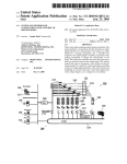
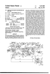
FIG. 1 is a block diagram of a multi-band, multi-con
35 one embodiment of this invention;
FIG. 2 is a detailed, schematic diagram of a portion
of the apparatus of FIG. 1; and
sively costly. Many of the digital indicators of the prior
art have not been sufficiently accurate to meet present 40
_
FIG. 3 isa series of waveforms for use in explaining
the operation of the apparatus of FIG. 2.
day requirements. Some of the digital tuning indicators
DESCRIPTION‘OF THE PREFERRED
of the prior art, such as that mentioned in the above
noted patent to Ertman, have not been capable of use
EMBODIMENTS
in multi-conversion radio apparatus. Some of the digi
tal tuning indicators of the prior art have not been
capable of use in multi-mode radio apparatus wherein
the same tuning apparatus is used to tune signals having
a plurality of different modes. Some of the digital tun
ing indicators of the prior art have relied for their oper
ation on the generation of signals at frequencies which
degraded the operation of the apparatus. As an exam
ple of the last-mentioned disadvantage, it has been
found to be particularly disadvantageous in radio re
ceiver digital tuning indicators to make use of a signal
-
The preferred embodiment of this invention will now
be described with reference‘ to FIGS. l-3 of the draw
45 ing. It will be apparent to those skilled in the art that
this invention is of much broader application than the
single embodiment shown in the drawing.
7
There is disclosed in FIG. 1 in block diagram form a
radio transceiver 8 including a double conversion su
perheterodyne receiver 10 and having a frequency
measuring apparatus 'of the present invention. The
transceiver 8 is capable of receiving and transmitting
signals in a plurality offdifferent frequency bands and in
either the continuous wave (CW), upper sideband
at the frequency of the signal being received as such a 55 (USB), or lower sideband (LSB) modes. The receiver
signal interferes with and degrades reception of the . 10 includes an antenna 12 coupled to an input of a
received signal.
SUMMARY OF THE INVENTION
bandpass ?lter 14 which, in turn, has its output coupled
to an input of a ?rst mixer 16. The bandpass ?lter 14 is
relatively broadly tuned so that it is effective to pass all
A digital, direct reading tuning indicator for a multi 60 signals received within one of the frequency bands of
operation of receiver 10. Further, the tuning of that
conversion, multi-mode radio apparatus is provided by
?lter may be altered so that its passband corresponds to
this invention which comprises apparatus for forming a
the different frequency bands of receiver 10. An output
signal having a frequency related to the frequencies of
of a high frequency oscillator 18 (HFO) is coupled to a
the local oscillator signals used in the apparatus, a
second input of ?rst mixer 16. The frequency of opera
digital counter for counting the frequency of that sig
tion of HFO 18 may be altered in accord with the fre
nal, and apparatus for altering the count obtained by
quency band to which the receiver is tuned but is
the digital counter by variable amounts dependent
chosen to be above all the frequencies in the corre
upon the mode of operation of the apparatus._
3,938,048
?lter 38 may be altered in accord with the band to
which the receiver 10 is tuned and is coupled to band
selector apparatus 32 for this purpose. Counter 40
sponding band. The ?rst mixer heterodynes the re
ceived RF signals with the output signal of the ‘HFO l8
and produces signals at frequencies equal to the sum
and differences of the frequency of the HFO and the
frequencies of the RF signals applied thereto by band
counts the number of cycles occurring during a ?xed
period of time in the premix signal. The output of the
counter is coupled to a display apparatus 42 which
gives a visual indication of the count achieved by
counter 40 and, thus, of the carrier frequency of the
signal received by the receiver 10. A counter program
mer 44 is provided which is coupled to both the mode
selector apparatus 34 and counter 40. The counter
programmer 44 programs the operation of counter 40
so that display apparatus 42 provides a direct visual
pass ?lter l4. The output of ?rst mixer 16 is applied
through a bandpass ?lter 20 to an input of a second
mixer 22. Bandpass filter 20 selects the difference fre
quency signals present in the output of ?rst mixer 16
and attenuates the sum frequency signals.
The output of a variable frequency oscillator 24
(VFO) is applied to a second input of second mixer 22.
The operating frequency of oscillator 24 is below the
reading of the frequency of the signal received by the
receiver. The programming is achieved by setting a
frequencies of the signals in the output of bandpass
?lter 20 and is continuously and manually variable over
a predetermined frequency range. The second mixer 22
predetermined number into counter 40 prior to the
commencement of the counting period. That preset
heterodynes the output signals of bandpass ?lter 20
with the output signal of the VFO 24 and produces
number is altered in accord with the nature of the
signals at frequencies equal to the sum and differences
of the frequency of the VFO and the frequencies of the
signals at the output of bandpass ?lter 20. The output
of second mixer 22 is applied through a bandpass ?lter
tuned signal, i.e., CW, USB, or LSB, and for CW sig
nals, according to whether the transceiver is being used
of the frequency spectrum occupied by a single re
counter 40, display apparatus 42, and counter pro
ceived RF signal.
grammer 44 will be futher discussed in relation to FIG.
2.
Also included within the transceiver 8 of FIG. 1 is
apparatus 45 to perform the transmit function. That
apparatus includes a modulator 46 having a ?rst input
coupled to the output of BFO 27 and a second input
as a transmitter or a receiver. The coupling between
the mode selector apparatus 34 and counter program
mer 44 effects this alteration. The construction of ap
26 to a detector 25. The bandpass ?lter 26 selects the
paratus to perform the functions of mixer 36 and band
difference frequency signals present in the output of
second mixer 22 and attentuates the sum frequency 25 pass ?lter 38 will also be apparent to those skilled in the
art and, accordingly, those circuits will not be further
signals. The passband of ?lter 26 is relatively narrow
discussed here. The construction and operation of
and, in particular, is of a width comparable to the width
'
A beat frequency oscillator 27 (BFO) having its out
put coupled to a second input of detector 25 is pro
vided. The frequency of the BFO for USB and LSB
signals is the frequency corresponding to the carrier of
the received signal and for CW signals is at a frequency
slightly offset from the frequency corresponding to the 35 coupled to a microphone for receiving audio speech
signals. Modulator 46 is also coupled to the mode se
carrier of the received signal. Detector 25 heterodynes
lector apparatus 34. The modulator 46 is such that
the signals applied thereto from bandpass ?lter 26 and
when the mode selector apparatus selects either the
BFO 27 to obtain an audio signal which is ampli?ed by
USB or LSB modes, the modulator produces at an
an audio signal amplifier 28 and reproduced by a
output a double sideband, suppressed carrier signal on
speaker 30.
the appropriate sideband with the frequency of the
Apparatus is also included within transceiver 8 for
suppressed subcarrier being the frequency of the out
controlling the band and mode of operation thereof. A
put of BFO 27. Whenthe mode selector apparatus 34
band selector apparatus 32 is provided which is opera
selects the CW mode, modulator 46 produces at its
tive to simultaneously control the frequency range to
which bandpass ?lter 14 is tuned and the frequency of 45 output a signal at the frequency of the output of BFO
27. The output of modulator 46 is applied through a
the HFO 18. A mode selector apparatus 34 is provided
bandpass ?lter 47 to remove the undesired sideband in
which is operative to alter the frequency of operation
of BFO 27 in accord with the mode of operation of the
transceiver, i.e., in accord with whether it is being used
the USB or LSB modes. The output of bandpass ?lter
47 is applied to a ?rst input of a mixer 48 while the
as a transmitter or receiver and whether with USB,
transceiver 8 additionally includes a mixer 36 having a
?rst input coupled to the output of HFO l8 and a sec
output of bandpass ?lter 38 is coupled to a second
input of that mixer. Mixer 48 produces at its output
signals at frequencies equal to the sum and difference
of the frequencies of the signals applied to the inputs
thereof. The output of mixer 48 is applied through a
bandpass ?lter 49 to the input of a radio frequency
ampli?er 50. The bandpass ?lter 49 selects the sum
frequency signals in the output of mixer 48 and attenu
ates the difference frequency signals. The center fre
quency of bandpass ?lter 49 may be altered in accord
ond input coupled to the output of VFO 24. Mixer 36
60 with the band to which the receiver 10 is tuned and is
LSB, or CW signals.
The components of the apparatus of FIG. 1 as thus
‘far described are well known and need not be further
discussed here. The construction of apparatus to per
form the required functions will be obvious to those 55
having ordinary skill in the art.
'
Turning now'to the features of this invention, the
coupled to band selector apparatus 32 for this purpose.
Radio frequency ampli?er 50 ampli?es the signal at its
the sum and difference of the frequencies of the signals
input, which ampli?ed signal is applied through a low
applied to the inputs thereof. The output of mixer 36 is
pass ?lter 51 to antenna 12. A key is associated with
applied through a bandpass ?lter 38 to a counter 40.
The bandpass ?lter 38 selects the difference frequency 65 ampli?er 50 for controlling the presence of a signal at
the output of ampli?er 50 during the transmission of
signal and attenuates the sum frequency signal and
CW signals. Low-pass ?lter 51 attenuates undesirable
produces at its output a signal hereinafter referred to as
high frequency components which may be present in
the f‘premix” signal. The center frequency of bandpass
is operative to produce signals at frequencies equal to
3,938,048
,
5
sents a‘ logic ‘level 0 signal. The premix signal from
bandpass ?lter 38‘is applied through 'a capacitor 53 to
the output of radio frequency ampli?er 50. The upper
cutoff frequency of low-pass ?lter 51 may be altered in
accord with the band to which the receiver 10 is tuned
the base of an NPN transistor 54. That base is coupled
and is coupled to band selector apparatus 32 for this
purpose. It will also’ be ‘necessary to include within
to a positive voltage supply V through a resistor 55 and
transceiver 8 circuitry for coordinating the operation'of
of transistor 54 is coupled to positive voltage supply V
the receiver 10 and transmitter 45 portions and so that,
in particular, the output of low-pass ?lter 5,1 is not
applied directly to the input of bandpass ?lter 14 when
radio frequency ampli?er 50 is operative. Both the
function and construction of such circuitry willv be
through a resistor 57. Transistor 54 and its associated
to a circuit ground through a resistor 56. The collector
components‘ form an ampli?er for the premix signal.
Theoutput of that ampli?er is taken from the collector
of transistor 54 and applied to the toggle input T of a
?rst clocked ?ip-?op 59. The output of ?ip-?op S9 is,
in turn, applied to the toggle input T of a second
clocked flip-?op 61‘. Flip-?ops 59 and 61 are such that
their outputs change states in response to the signals at
readily apparent to those skilled in the art and need not
be further discussed here. Similarly, the construction of
apparatus to perform the required function of the other
their inputs only when a logic level 1 signal is applied to
components of the transmitter 45 will be readily appar
the clock input thereof. They are also such that they
ent to those skilled in the art and need not be further
discussed here.
' I
s
may be reset so their outputs are at logic level 0 when
.
a logiclevel 0 signal is applied to reset inputs R thereof.
Flip-?ops 59 and 61 serve to divide the frequency of
the premix signal by four and, thus, reduce the fre
quency response requirements of the following circuit
One transceiver 8 of this invention was constructed
which was capable of both transmitting and receiving
signals on the 80, 40, 20, 15, and 10 meter amateur
radio bands and also of receiving signals on the. 15.0 to
l5.5 MHz band for reception of signals broadcast by
elements.
ment and broadcastingstandard radio, audio, and time
signals. The frequencies of the tuned radio signals and
the corresponding frequency of operation of HFO l8
'
Band
80 Meters
40 Meters
WWV
20 Meters
_
v
.
Signal '
HFO
BPF
Frequencies
l8 Frequency
38 Passband
15 Meters
3.5-4.0
7.0-7.5
l5.0-l5.5
14.0-14.5
,2l.0—2l.5
MHz
MHz
Ml-lz
MHz
l2.395
15.895
23.895
22.895
MHz
MHz
MHz
MHz‘
6.895-7.395 MHz
10395-10895 MHz
l8.395-l8.895 MHz
l7.395-l7.895 MHz
MHZ
29.895 MHz
24395-24895 MHz
10 Meters
28.0-28.5‘Ml-lz
36.895 MHz
3l.395_-3l.895 MHz
l0 Meters
10 Meters
28.5-29.0 MHz
29.0-29.5 MHz
37.395 MHz
37.895 MHz
3l.895-32.395 MHzv
32395-32895 MHz
l0 Meters
29.5-30.0 MHz
38.395 MHz
32895-33395 MHz
v
‘
ing the binary values 1, 2, 4, and 8, respectively, associ
ated therewith and four inputs P1, P2, P4, and P8 also
having the binary values 1, 2, 4, and 8, respectively,
associated therewith. A count/load input C/L is pro
and 'the passband of bandpass ?lter 38 are listed as
follows:
,
Thevoutput of ?ip-?op 61 is coupled to the count
input C of a ?rst presettable decade counter 58. The
counter 58 has four outputs Q1, Q2, Q4, and Q8, hav
WWV, a radio station operated by the U.S. Govern
30 vided. The counter 58 is such that when the count/load
input is at logic level I, each negative going pulse from
logic level I to logic level 0 applied to the count input
will cause the number represented by the outputs Q1,
Q2, Q4, and Q8 to advance‘by one, until reaching the
35 count of nine when the counter willreturn to zero, but
when the count/load input is at logic level 0, the binary
number represented by the inputs P1, P2, P4, and P8
will be set into the counter and appear on the counter
outputs. For inputs P1, P2, P4, and P8", an unconnected
40
In that transceiver, the passband of ?lter 20 is approxi
or isolated input is the equivalent of a logic level 1
signal.
,
mately '8.395-8.895 MHz, the range of operation of
VFO 24 is 5.0-5.5 MHz, the center frequency of ‘filters
The circuit of FIG. 2includes four additional decade
BFO 27 is 3.3936 MHz for LSB signals, 3.3964 MHz
for USB signals, and 3.3964'MHz for CW signals in the
receive mode and 3.3957 of CW‘signals in the transmit
60, 62, and 64 are each coupled to the count inputs'of
counters 62, 64, and 66, respectively. The Q8 output of
counters 60, 62, 64, and‘ 66 identical to' counter 58.
Output Q8 of counter 58 is coupled to the count input
26 and 47_are 3.395 MHz and their passbands are ap
proximately 2.1 kHz, and the frequency of operation of 45
_ of counter 60 and, similarly‘, the outputs Q8 of counters
mode. As previously mentioned, in order to generate
an audio tone for reception of CW signals, the fre
each counter has a negative going transition'from logic
level 1 to logic level 0' only when the stateof that
counter passes from nine to zero so that each counter
‘ quency of the BFO must be ‘offset from the CW carrier
60, 62, 64, and 66 advances one count when the pre
frequency by about 700 Hz. With this selection of BFO
ceding counter" 58, 60, 62, and 64, respectively, has
frequencies,‘ the 5 frequency used for USB signals,
_ counted ten pulses. Thus, the decade counters 58, 60,
3.3964 MHz, may also be used for reception of CW
signals at 700 Hz removed therefrom, i.e., signals ap
pearing at 3.3957 MHz in the output of bandpass ?lter
26. However, BFO 27 operates at the corresponding
carrier frequency of 3.3957 MHz during transmission
62,64, and 66 produce at their outputs in binary coded
55 decimal form a count of the pulses applied to the count
input of counter ‘58.
’ Five 4-bit latch memories 68, 70, 72, 74, and 76 are
provided, each having four inputs D1, D2, D3, and D4
of CW signals so that the output of the transmitter‘ will
‘and ‘four corresponding outputs‘01, 02, 03, and 04,
be at the same frequency as the received signal. '
respectively. Each four-bit latch memory includes a
Turning now to FIG. 2 of the drawing, thereis dis
clock input CP and is such that when the clock input is
closed therein apparatus, for performing the function of
counter 40, display_42, and counter programmerv 44 of
at logic level 1, the signals present at the output are the
the apparatus of FIG. 1 making use of the frequencies
same as the signals present at the corresponding inputs,
but when the clock input is at logic level 0, the signals
referred to in the immediately preceding paragraph. In
65 present at the outputs remain ?xed no matter what the
the following description of that apparatusv a conven
tion will be used wherein a positive voltage represents
a logic level I signal and a ground level voltage repre
state of the signals at the input. Outputs Q1, Q2, Q4,
and Q8 of decade counter 58 are coupled to inputs D1,
D2, D3, and D4, respectively, of 4-bit latch vmemory
3,938,048
7
and the outputs of countersf'60, 62,, 64, and 66 are
' similarly coupled to the inputs’ of four-bit latch memo- ’
ries 70,72, 74, and 76, respectively.
I
150 and 152 are‘ coupled to the Q outputs of the pre
ceding ?ipy-?ops 1'48‘and 150, respectively. The ?ip- >
. flopseach'prov'ide'a divide-by-2 function and provide a
signal at’ their outputs’ at one-half the frequency of the
signal applied to their inputs‘. Thus, the signals at the
outputs'of ?ip-?ops 148, 150, and 152 are at 50 Hz, 25
ment digit display. Five, seven-segment digit displays
88, ‘90, 92, 94,_and :96 are provided each appropriately
I-Iz,'and 12.5 ‘Hz, respectively. Of course, the signal at
the Q output of each ?ip-?op is merely the signal at the
coupled to a corresponding converter 78, 870, 82, 84,
and 86. Only the connections between converter 78
Q output but inverted.'
and digit display 88lare shown in FIG. 2 for economy of
20
104, and 106, respectively, to a source of relatively
high positive voltage B. Digit display 90 may also in
cludean ‘element for displaying a decimal point which
is coupled to circuit ground through a resistor 108. In 7 25
the total display provided by digit displays 88,90,92,
94, and 96, the digit represented by display 88 is the
least significant, that by display 90 the ‘next most signif
icant, and so on with the digit of display 96 being the
most signi?cant}Additionally, another binary-coded
decimal to ‘seven-segment c'onverter_1l0 and another
seven-segment‘digit display 112 identical to the other
converters" and displays are provided. Converter 110
kHz, 1" kHz, and 100 ‘Hz, respectively. Three flip-?ops
148, 150, and 152 are also provided gob having a
toggle input T and two outputs Q and Q. The toggle
input T of ?ip-?op 148 is coupled to the Q output of
decade counter 146 whileythe toggle inputs of ?ip-?ops
The outputs of the four-bit latch memories are each
coupledv to corresponding inputs of binary-‘coded-deci
mal to seven-segment converters 78,, 80, 82, 8,4,‘ and
86, respectively. Each-of thev converters has four inputs
R1, R2, R4, and R8 having binary values 1,, 2, 4, and 8,
respectively,_associated therewith and 7 outputs A,__B,
C, D, E, F, and G.‘ The converters are operative to
convert the number represented in binary form at their
inputs into‘ seven signals, operativeto drive a seven-seg
drawing, but the remaining digit displays are similarly
connected to theircorresponding converters. Each of
the digit displays ‘88, 90, 92, 94, and 96 includes an
anode element coupled through a resistor 98, 100, 102,
clock inputs. Thus, the signals at the Q outputs of
counters 140, 142, 144, and ‘146 are at 100 kHz, 10
30
'
'
The‘ appropriate timing signals are derived from the
outputs of decade counter 146 and ?ip-?ops 148, 150,
and 152. Output Q of ?ip-?op 152 is coupled to the
clock inputs of ?ip-‘?ops 54' and 56. Thus, output Q of
flip-?op 152 is used to gate the passage of the premix
signal from the ampli?er including transistor 54 to the
counter 58. 'A four-input NAND gate 154 is provide_cl
having ?rst through fourth inputs coupled to the Q
outputs of ?ip-?ops 148, 150, and 152, and the Q out
put of decade counter 146. The output of gate 154 is
coupled to the two inputs of a two-input NAND gate
156 which, in turn, has its output coupled to the clock
inputs C? of each of the four-bit latch memories 68, 70,
72, 74, and 76. A four-input NAND gate 158 is pro
vided having a ?rst input coupled to the Q output of
?ip-?op 152, a second input coupled to the Q output of
?ip-?op 150, and third and fourth inputs coupled to the
Q'output of ?ip-?op 148. The output of gate 158 is
verter'78 and display 88. The anode of display 112 is 35 coupled to‘ the reset inputs of ?ip-?ops 59 and 61.
Finally,’ a two-input NAND gate 160 is provid_e_d having
coupled through a resistor 114 to positive voltage sup
?rst and second inputs coupled to the Q and Q outputs
,ply B. Converter ‘110 has a'blanking input B 'which,
of ?ip-flops 150 and 152, respectively, and an output
when a logic' level 1 "signal is applied thereto, insures
coupled to the count/load inputs C/L of each of decade
that no digit is shown on display unit 112 no matter
counters 58, 60, 62, 64, and 66.
what signals are‘pres'ent'at inputs R1, R2, R4, and R8.
The operation of the timing circuitry will be ex
Inputs 8', RI, and R2 are coupled to circuit points 116,
plained with reference to FIG. 3. In that ?gure, seven
118, and 120,.respectively,.which, in turn, are coupled
waveforms labelled’ A-E are shown representing the
to the band selector apparatus 32 for reasons which will
and display .112 are interconnected just as are con
subsequently be made apparent.
'
'
signals appearing at the correspondingly labelled loca
' _ '
The apparatus of FIG. 24 also includes timing circuitry
for timing the operation of the counters and latch ‘mem
ories. ‘The; timing circuitry includes an ‘oscillator oper-.
45
tions in ‘FIG. 2.- The waveforms A-D represent the
signals‘ at the Q outputs of decade counter 146 and
?ip-?ops 148," 150, and 152, respectively. The logic
ating at 1 MHz. The'oscillator is comprised of a ?rst
NAND gate 122, a secondNAND gate 124, and a 1
MHz crystal 126. The output of gate 122 is coupled
through the parallel combination of ‘a resistor 128 and
level 1 portions'of' waveform D are used to gate the
divided down premix signal to the input of decade
counter 58 and, accordingly, are labelled “gate" in
a vcapacitor 130 to positive voltage supply V, through a
waveform E. As will be apparent from_2, it may be
represented in logic notation as A-B-CrD. The logic
FIG. 3. The signal at the output of gate 156 is shown at
resistor 132 to each of the inputs thereof, and to each
of‘ the inputs of gate 124. The output of gate v124 is
coupled to positive voltage'supply V'thro‘u'gh a resistor
55
' 134 and through‘v the parallel combination of a capaci
tor 136 and avariable capacitor 138 to a ?rst terminal
level 1 portions of waveform E are used'to transfer the
information present at the inputs of the four-bit latch
memories 68, 70, 72, 74, and 76 to the corresponding
outputs and, accordingly, are labelled “transfer" in
FIG. 3. The signal at the output of gate 158 is shown at
‘of. crystal 126. The second terminal of crystal 126 is
coupled to the inputs of gate 122. The output of the
'waveform F and may be represented as E-C-D. The
oscillator is taken'frorn ‘the output of gate 124 and
60 logic level‘ 1 portions of waveform F are used to reset
?ip-?ops 59 and 61 so that each of their outputs Q are
at logic level 0 at‘the commencement of a gate signal
and, accordingly, ‘are labelled “reset” in FIG. 3. The
applied to a clock input CP of a decade counter 140
having an outputQ. Three' additionaldecade counters
142, 144, and '146 are provided each having a clock
input CP coupled tothe‘output'Q of the preceding
counter 140, 142, and Y144, respectively. Each of the
decade counters is used‘to't'provide a divide-by-IO func
tion so, thatthey produce vat their outputs a signal at
one-tenth the frequency of the‘ signal applied_ to their
65
signal at the output of gate litLis shown at waveform G
and‘may be represented as CD. The logic level 1 por
tions oflwaveform G are usedito preset a given count
into decade counters 58, 60, 62, 64, and 66 prior to the
commencement of a' gate signal and, accordingly, are
N
3,938,048
9
labelled “preset” in FIG. 3.
H r
_
10
required that the frequency ‘of the premix signal be
_
As shown in FIG. 3, the sequence'of operation is as
counted but that the counter initially be programmed
follows. First, the ?ip-?ops 59 and 61 are reset and a
to a number below zero corresponding to the frequency
predetermined count set into decade counters 58, 60, _
of BFO 27.
62, 64, and 66. Second, the divided down premix signal
-
'
In the CW-receive mode the situation is slightly dif
'ferent. There the BFO frequency must be offset from
is gated to counter 58 so that it and the succeeding
counters count the premix signal during the count in
terval, which count is applied to the inputs of the four
bit latch memories 68, 70, 72, 74, and 76. Third, after
the frequency corresponding to the carrier frequency
by approximately 700 Hz and the carrier frequency of
the tuned signal is equal to the frequency of the premix
the termination of the gate signal, the count on the
displays 88, 90, 92, 94, and 96. Moreover, the digits
less the difference of the frequency of BFO 27 and 700
Hz. Thus, to achieve a direct display of the tuned signal
carrier frequency, the counter must be initially pro
grammed to a number below zero corresponding to the
frequency of BFO 27 less 700 Hz. For the BFO fre
displayed remain the same until after the completion of
the next gate signal.
quencies mentioned above, the frequency of BFO 27
during the CW-receive mode, 3.3964 MHz, less 700 Hz
In order to preset a count into decade counters 58,
is 3.3957 MHz and is equal to the BFO frequency used
during the CW-transmit mode. Thus, the number pro
grammed into the counters will be the same for both
20 the CW-transmit and the CW-receive modes despite
decade counters 58, 60, 62, 64, and 66 is transferred to
the outputs of four-bit latch memories 68, 70, 72, 74,
and 76. That transferred count is displayed on the digit
60, 62, 64, and 66, the P8 input of counters 58 and 60,
the P1, P2, P4, and P8 inputs of counter 62, the P1 and
P8 inputs of counters 64 and 66, and the P8 inputs of
counters 58 and 60 are all coupled to ground. The P1,
P2, and P4 inputs of decade counter 58 and the P1, P2,
the use of different BFO frequencies on those two
modes.
and P4 inputs of decade counter 60 are coupled to
-
From the discussion in the preceding two paragraphs
it is apparent that the number which is programmed
ground through resistors 162, 164, 166, 168, 170, and
172, respectively. A circuit point 174 is coupled to the 25 into the counters is related to the intermediate fre
anodes of diodes 176, 178, and 180 having their cath
quency of the transceiver for the corresponding mode
odes individually coupled to the P4 input of counter 58
of operation. The intermediate frequency is that fre
and the P2 and P4 inputs of counter 60, respectively. A
quency which corresponds to the carrier frequency of
circuit point 182 is coupled to the anodes of diodes
the signals present at the outputs of bandpass ?lters 26
184, 186, 188, and 190 having their cathodes individu 30 and 47 in the transceiver 8. In particular, even though
ally coupled to the P2 and P4 inputs of counter 58 and
different BFO frequencies are used in the CW-transmit
the P1 and P2 inputs of counter 60, respectively. A
and CW-receive modes, the intermediate frequencies
circuit point 192 is coupled to the anodes of diodes
on those two modes are the same and the same number
194, 196, and 198 having their cathodes individually
is programmed into the counters for operation in those
coupled to the _P1 and P2 inputs of counter 58 and the 35 two modes.
P4 input of counter 60, respectively- Circuit points
In the apparatus of FIG. 2, the frequency of the gate
signal is 12.5 Hz and it has a duration of one-half the
174, 182, and 192 are coupled to the mode selector
apparatus 34. Logic level 0 signals are applied to each
period of the 12.5 Hz signal or 0.04 sec. Further, the
of circuit points 174, 182, 192 except that when the
frequency of the premix signal is divided by 4 before it
transceiver is in the LSB mode, a logic level 1 signal is
is applied to counter 58. Thus, if the, counters 58, 60,
applied to circuit point 174, and, similarly, when the
62, 64, and‘66 were preset to zero prior to the com
transceiver is in the USB and CW modes, logic level 1
signals are applied to circuit points 182 and 192, re
mencement of eachgate pulse, the digit displays 88, 90,
92, 94, and 96 would display ?ve signi?cant digits of
the premix signal frequency, digit 88 being the least
signi?cant of the ?ve‘ digits displayed and representing
spectively.
.
It will be apparent that when the decade counters 58, 45
01 kHz and digit 96 being the most signi?cant of the
60, 62, 64, and 66 are preset, a count of zero is placed
in counter 62 and counts of 6 are placed into both
?ve digits displayed and representing 1,000 kI-Iz. 'How
counters 64 and 66. If, for example, the receiver is in
ever, as mentioned in the apparatus of FIG. 2, the
the LSB mode, a count of 4 is set into counter 58 and
counters 58, 60, 62, 64, and 66. are set to a count below
a count of 6 is set into ‘counter 60. Thus the number 50 zero which varies according to the mode of operation
preset into the counters is 66064. In the USB and CW‘
of the transceiver. For example, in the LSB mode on
modes, the numbers preset into the counters are 66036
either transmit or'receive, the counters are preset to
66064 so that a count of the BFO frequency, 3393.6
and 66043, respectively.
As mentioned, the frequency of HFO l 8 for any band
kHz, will set each of the counters 58, 60, 62, 64, and 66
of the transceiver 8 is above the frequency of any signal 55 to zero and the total count achieved by the counters
in that band. Further, the frequency of VFO 24 is al
ways below the frequencies of the signals present in the
output of bandpass ?lter 20. Thus, in the LSB and USB
modes and the CW-transmit mode the carrier ‘fre
quency of the tuned signal is equal to the frequency of
the HFO 18 less the frequency of the VFO 24 less the
frequency of the BFO 27. The premix signal which is
60
during a single gate pulse and displayed on the digit
displays will be equal to ?ve signi?cant digits of the
carrier frequency of the received signal. Digit 88 will be
the least signi?cant of the ?ve digits displayed and
represent 0.1 kHz and digit 96 will be the most signi?
cant of the digits'displayed and represent l,000 kHz.
The decimal point included in digit display 90 places
applied to the input of counter 40 has a frequency
the decimal between the digits of displays 88 and 90 so
equal to the frequency of the HFO less the frequency of
that the overall display provided by digits 88, 90, 92,
the VFO. Thus, the carrier frequency of the tuned 65 94, and 96 is in kHz. Digit display 112 provides a sixth
signal is equal to the frequency of the premix signal less
the frequency of BFO 27. In order to achieve a direct
signi?cant digit in'the display of the received carrier
frequency in representing 10,000 kHz. That digit could
display of the carrier frequency of the tuned signal, it is
be generated through the use of an additional decade
3,938,048
.
1 1
.
ceiver, the value of the sixth signi?cant digit is deter
mined by the frequency band to which the receiver is
tuned by band selector apparatus 32. Thus, circuit
12
tions in the frequencies of both the local oscillators,
counter coupled to counter 66 and an additional four
bit latch memory coupled to the additional decade
counter and the binary-coded-decimal to. seven-seg
ment converter 110. However, in the disclosed re
high frequency oscillator 18 and variable frequency
oscillator 24, such as might be caused by drift, operat
ing temperature variations, component aging, power
5
supply ?uctuations, etc. In this connection, it should be
noted that in most modern day, high quality receivers,
the beat frequency oscillator is crystal controlled so
that variations in its operating frequency are of rela
points 116, I18, and 120 are coupled to the band selec
tor apparatus 32 so that digit display 112 is blank when
tively minor importance compared to variations in the
frequency of the local oscillators.
Further, the accuracy of the disclosed apparatus is
the receiver is tuned to the 80 and 40 meter bands, so
that it displays the numeral 1 when the receiver is tuned
tothe WWVand 20 meter bands, and so that it displays
improved because even though it is used with a multi
conversion radio apparatus, it is only required to per
form a single counting operation each time the tuned
frequency is measured. This permits two ways in which
the accuracy of the apparatus may be improved. The
length of the counting period may be increased or the
the numeral 2 when the receiver is tuned to the 15 and
10 meter bands.
In one operative embodiment of a transceiver of this
invention, the components used are more fully identi
?ed as follows:
measuring apparatus may be performed at a faster rate.
46
36 pfd.
50
Sl
52, 53
54, 56
2N2369
3,900 ohms
1,000 ohms
SN74H I03
58, 60, 62, 64,
68, 70, 72, 74,
78, 80, 82. 84.
122, 124, I56,
66
76
86, I10
l60
74196
SN7475N
DM-8880
SN74OON
The second manner is especially advantageous when
20
the frequency of the tuned signal is changing rapidly,
especially during periods when the associated appara
tus is initially warming up.
While particular embodiments of the invention have
been disclosed herein, it will be understood, of course,
25 that the invention is not to be limited thereto since
I28. I34
I30
I32
680 ohms
0.005 mfd.
I50 ohms
many modi?cations may be made. It is contemplated,
therefore, by the appended claims, to cover any such
I36
138
I40, I42, I44, I46
5 pfd.
2—8 pfd.
SN7490N
SN7473N
SN7420N
220 ohms
modi?cations as fall within the true spirit and scope of
this invention.
I claim:
1. A digital tuning indicator for use with a multi-con
version radio apparatus including a plurality of local
148,150, 152
I54, 158
162, 164, I66, I68, I70,
l72
30
oscillators, said indicator comprising:
I88. I90, I94, I96, 198
mixing means coupled to each of said local oscillators
35
nections to many of the circuit elements have not been
shown. However, the manner in which they are sup
and forming a premix signal having a frequency
responsive to the frequencies of operation of said
local oscillators;
counting means coupled to the output of said mixing
plied will be apparent to those skilled in the art. In
means and forming a count responsive to the num
constructing an apparatus of FIG. 2 if a common power 40
ber of cycles of said premix signal occurring over a
In FIG. 2, the required power supply and ground con
period of predetermined length;
supply is used as positive voltage source V, it is desir
able to include means for blocking the flow of high
frequency signals between the various components
through the power supply connections.
It will be apparent that the display apparatus of this
invention may readily be adapted for other modes of
operation of the transceiver 8_. For example, if that
transceiver were operative in the amplitude modulation
display means coupled to said counting means for
displaying the count achieved by said counting
means at the end of said period; and
45
programming means coupled to said counting means
for altering the count attained on said counting
means by an amount related to an intermediate
frequency of said radio apparatus.
(AM) mode, in order to obtain a correct indication of
2. The digital tuning indicator of claim 1 wherein said
the carrier frequency of the tuned signal, it would
50 programming means further loads a count into said
merely be necessary to program a count into the count
ers 58-66 which is less than zero by an amount corre
counting means related to an intermediate frequency of
said apparatus prior to the commencement of said
sponding to the center frequency of bandpass ?lter 26,
that frequency then being the intermediate frequency
period.
3. A digital tuning indicator for use with a multicon
of receiver'l0. In the AM mode, of course, BFO 27 55 version radio apparatus having a single apparatus for
tuning signals of a plurality of modes and including a
would not be required for the operation of receiver 10
plurality of local oscillators, said indicator comprising:
but only for transmitter 45.
mixing means coupled to each of said local oscillators
It will thus be seen that frequency measuring and
each of the aforementioned objects. In particular, the
disclosed apparatus provides a direct reading, visual
frequency indicator which is operable with multi-fre
and forming a premix signal having a frequency
responsive to the frequencies of operation of said
local oscillators;
counting means coupled to the output of said mixing
quency conversion radio apparatus capable of tuning
means and forming a count responsive to the num
indicating apparatus have been provided which ful?ll
ber of cycles of said premix signal occurring over a
signals in a plurality of different modes. The disclosed
apparatus is economical in that relatively inexpensive
and readily available components are used to provide
65
period of predetermined length;
display means coupled to said counting means for
the desired display. The disclosed apparatus is highly
displaying the count achieved by said counting
accurate in that it compensates for unintentional varia
means at the end of said period; and
3,938,048
13
~
14
programming means coupled to said counting means
for altering the count attained on said counting
display means coupled to said counting means for
means by an amount variable in response to alter
means at the end of said period; and
programming means coupled to said counting means
for loading a count into said counting means prior
to the commencement of said period, said count
being variable in response to alterations in said
displaying the count achieved by said counting
ations in the mode of said tuned signal.
4. A radio apparatus comprising:
tuning means including a ?xed frequency local oscil
lator and a variable frequency local oscillator;
detection means including a beat frequency oscilla
tor;
intermediate frequency.
6. A multiple frequency conversion radio receiver
.
mixing means coupled to said ?xed frequency local 10
oscillator and said variable frequency local oscilla
tor and forming a premix signal having a frequency
responsive to the frequencies of operation of said
local oscillators;
counting means coupled to the output of said mixing
comprising:
means and forming a count responsive to the num
period of predetermined length;
20
means at the end of said period; and
programming means coupled to said counting means
25
varies in response to variations in the frequencies
of said ?rst local oscillator signal and said second
means and making a count responsive to the num
ber of cycles of said premix signal occurring over a
period of predetermined length;
display means coupled to said counting means for
frequency conversion radio apparatus having a single
tuning apparatus operable at a plurality of intermediate
indicator comprising:
forming a premix signal having a frequency which
local oscillator signal;
counting means coupled to the output of said mixing
for loading a count into said counting means vari
able in response to alterations of an intermediate
frequencies and including a ?rst circuit for generating a
?rst local oscillator signal and a second circuit for gen
erating a second local oscillator signal, said tuning
nominally ?xed frequency and a second circuit for
generating a second local oscillator signal at a vari
mixing means coupled to said ?rst local oscillator
circuit and said second local oscillator circuit and
display means coupled to said counting means for
frequency of said apparatus prior to the com
mencemet of said period.
5. A digital tuning indicator for use with a multiple
cuit for generating a ?rst local oscillator signal at a
able frequency;
ber of cycles of said premix signal occurring over a
displaying the count achieved by said counting
a single tuning apparatus operable at a plurality of
intermediate frequencies and including a ?rst cir
displaying the count achieved by said counting
30
means at the end of said period; and
programming means coupled to said counting means
for altering the count attained by said counting
means by an amount variable in response to alter
’
ations in said intermediate frequency.
mixing means coupled to said ?rst local oscillator
7.
The radio receiver of claim 6 wherein said pro
35
circuit and said second local oscillator circuit and
gramming
means further loads a count into said count
forming a premix signal having a frequency which
ing means prior to the commencement of said period,
varies in response to variations in the frequencies
said count being variable in response to alterations in
of said first local oscillator signal and said second
said intermediate frequency.
local oscillator signal;
8. The radio receiver of claim 7 wherein the fre
40
counting means coupled to the output of said mixing
quency of said ?rst local oscillator signal is greater than
means and forming a count responsive to the num
the frequency of said second local oscillator signal.
ber of cycles of said premix signal occurring over a
=l<
*
*
=l<
*
period of predetermined length;
45
55
65