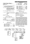
1
US 20050134872A1
(19) United States
(12) Patent Application Publication (10) Pub. No.: US 2005/0134872 A1
(43) Pub. Date:
Makl
(54)
Jun. 23, 2005
Related U.S. Application Data
SYSTEM AND METHOD FOR
CLOSED-LOOP COLOR CONTROL OF
PRINTED MEDIA
(60)
Provisional application No. 60/530,587, ?led on Dec.
18, 2003.
Publication Classi?cation
(75) Inventor: Santtu Maki, Varkaus (Fl)
(51)
rm.c1.7 ................................................... .. G06F 15/00
U.S. c1. ............................ ..358/1.6;358/1.9;358/1.1
Correspondence Address:
(52)
Anthony Miologos, Esq.
(57)
HONEYWELL INTERNATIONAL INC.
There is provided a printing control system and method. The
Patent Services Department
system includes a measurement unit that provides an output
signal indicative of a characteristic of an image on a media
formed by a printing mechanism, and a controller that
101 Columbia Road
Morristown, NJ 07962 (US)
(73) Assignee: HONEYWELL
INTERNATIONAL
INC.
(21) Appl. No.:
11/015,858
(22) Filed:
Dec. 17, 2004
ABSTRACT
responds to the output signal to modify an operation of the
printing mechanism to change the characteristic of the
image. The system also includes a processor that performs at
least one operation based on the output signal. The method
includes the steps of measuring a color density of selected
images printed on a media by a print mechanism, providing
at least one output signal indicative of the color density, and
modifying an amount of ink used to print the images based
on the output signal so as to change the color density.
112
122
110
110
126
102
/ _
Hamill-Ions
127
Quality Damian 8am"
128
124
-—P 106
160
/
108
104
\
/
116
114
Pro-press VF
130
.
coma cl
"liking Mm.
Cloud Loop Odour
time.
coma Mm.
132
118
Patent Application Publication Jun. 23, 2005 Sheet 1 0f 10
US 2005/0134872 A1
111".’r
/
—110
192
108
120
‘
_F_ 106
\
104
I ‘1/
/ 114
_
129
/
118
FIGURE 1
116
\
Patent Application Publication Jun. 23, 2005 Sheet 2 0f 10
US 2005/0134872 Al
mu-E:
mt
,,
m2
m:02
NM DOE
Patent Application Publication Jun. 23, 2005 Sheet 3 0f 10
US 2005/0134872 A1
Wn130i
EgsEK-cg
ma
ng. i.$n £ea2w!s‘[email protected]
g3
Patent Application Publication Jun. 23, 2005 Sheet 4 0f 10
400
415
‘1,12
FIGURE 4
410
III‘I'I IIIII IIIIIIIIII
FIGURE 5
\
US 2005/0134872 A1
Patent Application Publication Jun. 23, 2005 Sheet 5 0f 10
600
FIGURES
US 2005/0134872 A1
Patent Application Publication Jun. 23, 2005 Sheet 7 0f 10
US 2005/0134872 A1
828
Speed Pre-settings
Pre- se ttings
/
820
816
T
Operator Entries
/'
Tuning
argef
Parameter
Handling
822
H
/
dun
an
g
5
w
g 832
g as
E: 5
8
2 :1:
Ink Roller I
c n. l
Ink Roller
on o
810
8 ,
802
_‘6
E92
806
m
Control
E 5
812
818
Output
Handling
:
;4
j
808
'
814
Status
82:
Handling
Op erator Entries
‘\804
Interlock Settings _
Operator Entriesl
i
“ 826
FIGURE 8
830
Patent Application Publication Jun. 23, 2005 Sheet 8 0f 10
US 2005/0134872 A1
Density target
-lntenslty measurement
-lntensity ratio array
array
-lntensity ratio average
-Density mesurement
array
-Target density average
-Density deviation
-Setpoint modi?cation
average
from display or quality
FIGURE 9
Mode arrayto control
Measurement
U m m a E m .n e 5
1.
Mode
modifioationfrom
‘
Status to
displa 3,6
d spi ay or qJaIity
hten oaks
FIGURE 10
Patent Application Publication Jun. 23, 2005 Sheet 9 0f 10
US 2005/0134872 A1
Tuning
parameters
FIGURE 11
Tuning
parameters
- adap?ue to
machine qleed
Intensity ratio
. ink k9!
setpoint pro?le
speci?c
ratio
array
measurement pm?
. dam
Mode array
FIGURE 12
Patent Application Publication Jun. 23, 2005 Sheet 10 0f 10
US 2005/0134872 A1
Preset prdile
A
CV army
Opem‘tor ertries
I Odput modfication
from d spl ay or quality
keyboard
Mode array
‘I.
FIGURE 13
Jun. 23, 2005
US 2005/0134872 A1
SYSTEM AND METHOD FOR CLOSED-LOOP
COLOR CONTROL OF PRINTED MEDIA
[0011] A printing control system and method is provided
for control of printing devices. The printing control system
embodiment of the present invention includes a measure
CROSS-REFERENCE TO RELATED
APPLICATIONS
ment unit that provides an output signal indicative of a
characteristic of an image on a media formed by a printing
mechanism, and a controller that responds to the output
[0001] The present application is claiming priority of US.
signal to modify an operation of the printing mechanism to
change the characteristic of the image.
Provisional Patent Application Ser. No. 60/530,587, ?led on
Dec. 18, 2003, the content of Which is herein incorporated
by reference.
[0012] In another embodiment of the present invention,
the characteristic is a color density of the image.
[0002]
BACKGROUND OF THE INVENTION
[0013] In another embodiment of the present invention,
1. Field of the Invention
the output signal is indicative of a measurement of the color
density. The controller modi?es an amount of ink supplied
[0003] The present invention relates to printing systems,
by the printing mechanism for printing on the media based
and more particularly, to color control and monitoring
systems for commercial printers such as neWspaper printers.
on a deviation betWeen the measurement of the color density
[0004] 2. Description of the Related Art
[0005] NeWspapers are produced predominantly accord
ing to the offset process. A plurality of paper Webs are
and a target color density value.
[0014] In another embodiment of the present invention,
the ink is of a color selected from the group consisting of:
black, cyan, magenta, yelloW and any combinations thereof.
unWound from rolls, printed in the printing units and ?nally
[0015] In another embodiment of the present invention,
folded and cut. The inking can be set Zone by Zone in
the printing mechanism is a printing press. The measurement
unit is in an on-press or off-press position.
conventional inking systems. The system supplying ink to
the printing plate and thereon to the Web is divided into
Zones. For each Zone there is a device controlling the amount
of supplied ink. The device can be, for eXample, a pump (i.e.,
one pump per Zone), one or more blades scraping a roller
Where the gap betWeen the blade and the roller de?nes the
amount of ink supplied together With the ink fountain roller
speed. For each Zone the opening of the pump or the siZe of
the gap is controlled. The printer monitors the inking during
the entire production and makes corrections in inking When
[0016] In another embodiment of the present invention,
the printing control system includes a user interface in
communication With the controller. The interface can dis
play the output signal and receive one or more target
characteristics.
[0017] In another embodiment of the present invention,
the printing control system includes a processor that per
forms at least one operation based on the output signal.
necessary.
[0006]
Current neWspaper production has seen a dramatic
increase in the use of color printing. Color printing requires
the use of more complex printing techniques and color
management that if not properly managed can result in Waste
[0018] In another embodiment of the present invention,
the operation includes providing a record of the output
signal.
and degraded quality.
[0019] In another embodiment of the present invention,
the characteristic is a color density of the image. The output
[0007]
signal is indicative of a measurement of the color density,
and the operation includes providing a record of the color
Therefore, there is a need to provide both an
on-line and off-line closed-loop color control management
system for neWspaper and commercial printing presses.
density measurement.
[0020] In another embodiment of the present invention,
SUMMARY OF THE INVENTION
the printing control system includes a database that receives
and stores the output signal.
[0008] The closed loop color control system of the present
invention provides a device that measures the colors on a
printed product, presents color measurements to a user With
respect to the current color targets, provides for automatic
control of printing devices, and provides color quality
reporting. The system is useful in neWspaper production,
hoWever, it can also be used to advantage in other commer
[0021] In another embodiment of the present invention,
the operation includes providing a record of all output
signals made during a selected duration of a printing task.
[0022] In another embodiment of the present invention,
the printing control system includes a user interface. A user
cial and packaging printing applications.
can input a target color density value, and the operation
includes providing a report including data representing the
[0009] The system helps to keep the colors of the printed
product uniform throughout the production, decreases the
color density measurement, the target color density value,
start-up Waste as Well as the run-time Waste, increases
and the target color density value.
production ef?ciency and provides quality proofs in the form
and/or a deviation betWeen the color density measurement
present invention are a higher and more even print quality,
[0023] A method embodiment of the present invention
includes measuring a color density of selected images
printed on a media by a print mechanism, providing at least
one output signal indicative of the color density, and, based
material savings in paper and ink Waste, improved press
output capacity and reduced quality assurance costs.
print the images so as to change the color density.
of reports on product quality.
[0010]
The bene?ts of the system and method of the
on the output signal, modifying an amount of ink used to
Jun. 23, 2005
US 2005/0134872 A1
[0024] In another embodiment of the method of the
present invention, modifying the color density is based on a
deviation betWeen the color density measurement and a
target color density value.
[0025] In another embodiment of the method of the
present invention, the color density is measured from a
[0042] FIG. 12 is a portion of the block diagram of FIG.
8 shoWing the control function of the color control softWare.
[0043] FIG. 13 is a portion of the block diagram of FIG.
8 shoWing the output handling function of the color control
softWare.
preselected portion of the image.
DESCRIPTION OF THE INVENTION
[0026] In another embodiment of the method of the
present invention, the media is paper and the preselected
tem for use in color printing devices such as a neWspaper
portion is a gray bar.
printing press. The main components of the closed-loop
[0027] In another embodiment of the method of the
present invention, the printing mechanism is a printing
press, and the measurement is performed on the printing
press or off of the printing press.
color control system include on-press measurement sensors
[0044]
There is provided a closed-loop color control sys
that take color measurements, such as by reading color
densities, of the ink printed on a Web of materials. Also
included is a control system that receives color measurement
information and target density information, provides a dis
[0028] In another embodiment of the present invention,
play of such information to an operator, and can modify
the method includes providing a processor With the output
signal to provide a record of color density measurements
made during a selected duration of a printing task.
printing components based on measured density informa
tion. The system also includes a quality reporting system
that collects and displays measured and target density infor
mation for revieW and analysis.
[0029] In another embodiment of the present invention,
the method includes storing the color density measurements
in a database.
[0030] In another embodiment of the method of the
present invention, the method includes providing at least one
target color density value. The record includes data repre
senting the color density measurement, the target color
density value, a deviation between the color density mea
surement, and/or the target color density value.
BRIEF DESCRIPTION OF THE DRAWINGS
[0031]
FIG. 1 is a diagram of a printing device control and
monitoring system.
[0032]
FIG. 2 is a diagram of an on-press color control
and monitoring system.
[0033]
FIG. 3 is a diagram of an off-press color control
and monitoring system.
[0034]
FIG. 4 is an on-press measurement bar as posi
tioned over a Web.
[0035]
FIG. 5 is a plan vieW of a measurement bar.
[0036] FIG. 6 is an on-press control system Web on Which
pages have been printed from a doubleWide, double-around
printing press.
[0037] FIG. 7 is an eXample of a page operation display
interface in density control mode.
[0038]
FIG. 8 is a block diagram shoWing the color
control softWare functions.
[0039] FIG. 9 is a portion of the block diagram of FIG. 8
shoWing the target handling function of the color control
softWare.
[0040] FIG. 10 is a portion of the block diagram of FIG.
8 shoWing the status handling function of the color control
softWare.
[0041]
FIG. 11 is a portion of the block diagram of FIG.
8 shoWing the tuning parameter handling function of the
color control softWare.
[0045] A color measurement device is integrated With a
control system that receives color measurement data from
the color measurement device and that controls ink keys, ink
rollers, and other components of a printing press. An
eXample of a preferred control system is the PrintaTM Press
Control and Printa Production Management System sold by
HoneyWell International Inc.
[0046] In a preferred embodiment, the production operator
interface is completely integrated With a standard Printa
page-oriented operation. The operator uses the standard
operating displays that visually present both the measured
color densities and the target color densities. The displays
can also provide reports by the quality reporting system.
Adjustments of the color densities are performed on the very
same keyboard used for controlling ink Zones or are per
formed directly on the display using the user-friendly touch
screen. No separate monitors are required for the operation.
The operator is able to run the system in automatic mode or
disable the automatic control to operate the system in
manual mode. In automatic mode, the control system auto
matically adjusts the ink Zones and ink fountain rollers to
achieve the desired target densities, While the operator is
able to simultaneously make adjustments to the target den
sities. When the automatic mode is disabled then the opera
tor interacts directly With ink Zones.
[0047] Referring to FIG. 1, a printer apparatus includes a
printing mechanism 102 and a control system 100 of the
present invention. Printing mechanism 102 Which, for
eXample, may be a printing press, includes a reel stand 104,
a printing unit 106 including inking units 108 and a Web 110.
Control system 100 includes a color measurement unit 112,
a printing control mechanism, i.e., controller 114, a user
interface 116, and a control system bus 118. Aprocessor 120
is also provided. Press controller 114, for eXample, may be
the Printa Press Control System manufactured by HoneyWell
International Inc., and a quality reporting system.
[0048] Web 110, for eXample, may be paper, plastic or any
other material suitable for printing. Web 110 is advanced
from reel stand 104, through printing mechanism 106, and to
a folding and cutting mechanism (not shoWn) by a Web
advancement device (not shoWn). Printing unit 106, in one
Jun. 23, 2005
US 2005/0134872 A1
example, is con?gured to print With various color inks, such
as black, cyan, magenta, and yellow.
[0049]
Color measurement unit 112 takes measurement
data based on characteristics of one or more images printed
on Web 110 or a portion of Web 110, such as color density
measurements, and sends measurement data in the form of
one or more output signals to controller 114 via control
system bus 118. An interface (not shoWn) is provided to
facilitate transmission of the output signal, and performs
functions such as analog/digital conversion and signal shap
ing. The interface may be, for eXample, a PMD-controller.
Controller 114 receives the output signal from measurement
unit 112.
[0050] Controller 114 receives input, such as preselected
or preferred, i.e., “target”, measurement parameters, from
user interface 116, and modi?es printing unit 106 based on
a deviation betWeen actual measurement data and target
measurement parameters. In one embodiment, the output
signal carrying actual measurement data is a measure of
color density of the image, and controller 114 modi?es an
amount of ink supplied by printing mechanism 106 for
printing on Web 110 based on a deviation betWeen the
density measurement and the target color density value. The
target color density is a value to Which the color density
measurement is compared to determine the deviation
betWeen the color density measurement and the target color
density value. An error signal is generated based on the
deviation to correct the amount of ink provided by printing
unit 106.
[0051] User interface 116, such as a control desk, is in
communication With controller 114 via bus 118. User inter
face 116 may include components such as a processor,
memory, a screen and various inputs such as a keyboard,
mouse or a touchscreen. User interface 116 alloWs a user to
select image characteristics such as color density, and input
preselected or preferred, i.e. target, image characteristics.
Such target characteristics may be entered prior to com
mencement of a printing task, and neW target characteristics
may be added during the printing task.
[0052] System 100 also retains measurement data during
the printing process for presentation to a user during and/or
after the printing process. Processor 120 performs at least
one operation in response to receiving the output signal of
measurement unit 112. Processor 120 keeps a record of
measurement data represented by the output signals. Pro
cessor 120 can provide real time measurement data or a
features include one or more optional Workstations 126,
quality database server 128, pre-press interface 130, and a
production management server, i.e., a PMS server 132 that
is in communication With control system 100 via bus 118. A
router 134 delivers measurement information to devices
such as one or more Workstations 126 or a quality database
server 128.
[0055] Workstations 126 are used, for eXample, for pro
duction planning, production monitoring and reporting. A
pre-press interface 130 is used for pre-setting printing area
density pro?les for ink keys.
[0056] Upon activation, on-press measurement units 112
perform a search for measurement marks, such as gray bars,
measure the color densities of the measurement marks, and
provide the measure of color density data to press control
system 100. Measurement units 112 may provide an output
signal that is converted by controller 114 or another device
into density data, or may derive the density data and transmit
the density data to controller 114.
[0057] Press control system 100 performs numerous func
tions. Press control system 100 con?gures measurement
units 112 and press 102 at the start of the production run for
color density data collection. Press control system 100 also
provides control softWare to adjust ink keys and ink fountain
rollers (“ink rollers”) (not shoWn) of printing devices 106,
provides input/output operation (I/O) for user and/or opera
tor interface 116, and provides data to a quality reporting
system.
[0058] The quality reporting system may be implemented
in any of the computing devices that communicate With bus
118. These computing devices include Workstations 126,
database server 128, pre-press interface 130, PMS server
132, user interface 116 as Well as a remote computing device
that communicates With control system 100 by a netWork.
These computing devices, When implemented as the quality
reporting system, each include processor 120 and an asso
ciated memory. By Way of eXample for the present descrip
tion, quality reporting system is implemented herein as a
Workstation 127.
[0059] Quality reporting system 127 retrieves data repre
senting actual and target image characteristics, such as
actual measured color density and target color density, from
quality database server 128 for presentation to a user, either
during a printing task or after a printing task. The data may
be presented in various forms to provide a user With desired
report of part or a Whole of a printing task, ie a printing run,
quality information or speci?c quality reports.
for evaluation and quality control. In another embodiment,
[0060] FIG. 3 illustrates another alternative embodiment
of control system 100 that has off-press measurement units
112 (not shoWn) that are integrated into a color measurement
processor 120 may be incorporated With controller 114 or
user interface 116.
[0053] FIG. 2 shoWs another embodiment of control sys
tem 100 of FIG. 1, having on-press measurement units 112
and including multiple printing units 106 and additional
control system features. Multiple controllers 114 are con
nected to control system bus 118. Controllers 114 are each
in communication With one of printing units 106 for printing
on Webs 110, and in communication With user interface 116,
such as one or more control desks. The printing press also
includes turning bars 122 and folding/cutting mechanism
124.
[0054] Also shoWn in FIG. 2 are additional features of the
system of FIG. 1 for use in any control system. These
scanner 136.
[0061] Color measurement scanner 136 is located off of
printing press 102 and is used to read the color densities of
images on Web 110. Printed pages are transferred to scanner
136 after they are taken off of press 102. Measurement unit
112 in scanner 136 retrieves color measurement data and
sends the data to controller 114 via bus 118. Color measure
ment data may also be sent to Workstations 126 or other
components via router 134. A personal computer may be
included to retrieve data from off-press measurement units
112 and send the data to press controller 114. The measure
ment data is also provided to quality reporting system 127.
Jun. 23, 2005
US 2005/0134872 A1
[0062] Quality reporting system 127 retrieves color den
[0070]
sity data and other data as required from press control
ment of a measurement device 112 for use With control
system 100, and provides the data to computing devices such
system 100. Measurement device 112 includes color sensors
for color density measurement on the press. Color may be
as Workstations 126, quality database server 128, controller
114 and user interface 116. In another embodiment, quality
reporting system 127 stores the data collected to quality
database server 128, and provides the collected data, and
visualiZation and quality tools for vieWing and analyzing the
FIG. 4 and FIG. 5 illustrate an exemplary embodi
measured, for example, by a densitometer.
[0071]
As shoWn in FIGS. 4 and 5, measurement unit 112
includes a measurement bar 400 for each side 405 of Web
ments and density targets during the entirety of a printing
110 requiring online color measurement. Measurement bar
400 includes a plurality of modules 410. In one embodiment,
each module 410 contains ?ve measurement units 415. Each
measurement unit 415 includes three measurement channels
420: one measurement channel for each of the colors Cyan,
run. This information can be used to evaluate a printing run
Magenta and YelloW. Thus, each module 410 contains 15
data, to Workstations 126.
[0063]
Quality reporting system 127 can provide a user
With a continuous record of actual color density measure
and determine needed changes and/or improvements.
[0064] An exemplary method is provided for conducting
the Work?oW of a printing device such as a press using the
closed-loop color control system.
[0065] Prior to printing, during the pre-press process,
halftone gray bars are inserted in a printed product layout.
Plates are then produced and page data is sent to the
pressroom system for calculation of printing area coverage
pro?les, Which Will be used for ink key pre-setting. Alter
measurement channels. Each measurement channel 420
contains a light-emitting diode (LED) (not shoWn), emitting
either Red, Green, or Blue light, and a photodiode (not
shoWn) for re?ectance measurement.
[0072]
The siZes of modules 410 and measurement units
415 are ?xed. The number of modules 410 per measurement
bar 400 is de?ned by the Width of Web 110. A typical
exemplary number of modules 410 per measurement bar 400
is 11 modules.
natively, the ink key pre-setting may be accomplished prior
[0073]
to or at the start of a printing run.
ured from an external device and the data can be read by a
processor 435 from measurement bar 400 and transmitted
via a netWork, such as, an Ethernet 430.
[0066] Imposition plans are then created for the produc
tions. This information includes the exact positions of each
page and color on the press, thereby enabling the user to
concentrate on the product. This information also includes
the de?nition of the positions and types (3-color or black) of
the gray bars for each plate.
[0067] Color density measurements are performed by
color density measurement unit 112 on selected images
printed by printing unit 106. In a ?rst embodiment, on-press
measurement units 112 are utiliZed. When the printing of the
selected images starts, on-press measurement units 112
immediately start measuring the color densities across the
selected image printed on Web 110. In a second alternative
embodiment, off-press measurement scanners 136 are uti
liZed. The off-press measurement embodiment can be used
in place of the on-press measurement embodiment. In the
case of off-press measurement, the frequency of the mea
surement is dependent on the user’s manual operation. The
user can immediately see the measured densities on an
interface such as control desk 116.
[0068] Control system 100 can constantly calculate neW
values for the ink keys and/or ink fountain rollers to com
In one embodiment, modules 410 can be con?g
[0074] Various measurements may be performed by each
measurement unit 415. Such measurements include 1) inten
sity of each of C,M,Y in a 3-color gray bar, 2) color intensity
in an area just prior to or after a 3-color gray bar, 3) black
intensity of a 1-color gray bar, 4) color intensity in an area
just prior to or after a 1-color gray bar, and 5) color intensity
in a plate gap (area betWeen pages, Which should be plain
paper).
[0075]
Measurement bar 400 also includes an interface
(not shoWn) to synchroniZe pulses, for synchroniZation of a
printing cylinder 425. As cylinder 425 rotates, measurement
modules 410 receive pulses that indicate the angle of cyl
inder 425. In one embodiment, there are a minimum of 2,000
pulses per cylinder revolution. In addition, one pulse is
provided per revolution of cylinder 425 for reference. An
exemplary poWer supply (not shoWn) is 220V.
[0076] Measurement unit 112 takes color measurements
from selected images on each page of a printed Web 110. In
a preferred embodiment, measurement unit 112 provides
color density information from narroW halftone gray bars
pensate for any detected deviation betWeen color density
measurements and target color density parameters. If the
printed on each page, such as in a neWspaper printing press.
user has enabled the automatic mode, corrections are per
can be used as a reference to control color density. In the
case of a neWspaper printing press, tWo gray bars are
formed automatically by controller 114. During the produc
tion run, the user can adjust target color density values using
the standard press control desk interface 116.
In additional embodiments, other printed portions of a page
typically used. A ?rst type of gray bar is a 3-color Cyan,
Magenta, YelloW (CMY) neutral gray bar, and second type
of gray bar is a single gray bar for measuring black color.
[0069]
In one embodiment, control system 100 saves color
density measurements and target color density values into
database 128 for quality reporting and analysis purposes.
The measured densities can be presented visually in real
time on, for example, to Workstations 126 for comparison
With target densities. The data is also available for produc
tion reports to be sent to customers or for internal process
improvement.
The narroW gray bars are hidden in the neWspaper layout.
[0077] Typical gray bar compositions as halftone percent
ages are described beloW. An exemplary three color gray bar
includes a Cyan halftone percentage of 30%, a Magenta
halftone percentage of 22%, and a YelloW halftone percent
age of 22%. An exemplary halftone percentage of black in
a single color gray bar is 30%
Jun. 23, 2005
US 2005/0134872 A1
[0078]
FIG. 6 shows gray bars on a product’s pages on a
doubleWide, double-around press. In this example, a plural
ity of page areas 600 each contain one of a 3-color gray bar
605 or a 1-color gray bar 610.
[0079]
During one cylinder revolution, tWo of pages 600
(either the same or different pages depending on the pro
duction mode) are printed on a Web 615. Content 620
represents page content. All pages 600 contain a gray bar
605 or 610 for color measurement. Every other page in the
machine direction contains 3-color gray bar 605 and every
other alternate page contains 1 color gray bar 610.
[0080] In a single or double Width, single around neWs
paper printing process, both types of gray bars Would be
found on the same page.
[0081]
FIG. 7 is a representation of an eXample of a page
operation display 700 in the density control mode, as may be
displayed, for eXample, in user interface 116. Display region
705 provides a visual representation of the measured color
densities for each of printing Zones 1-10 on a selected page
on a Web. Printing Zones 1-10 each correspond to an ink key.
The number or printing Zones can vary betWeen different
printing presses. Region 705 also illustrates each Zone’s
[0086] Referring to FIG. 9, target handling function 802
receives information in the form of a density and intensity
measurement arrays/pro?les from measurement handling
function 832, Which receives density measurements from
color sensors 818, and also receives the pre-set density set
point/target pro?le, i.e. pre-settings 820. In the case of
measurement bar 400 as described in FIGS. 4-5, the array
contains all measurements from one measurement bar 400.
In one embodiment, the measurement values are running
averages With a varying length (e.g. last tWo values, last four
values). Target handling function 802 may also receive ink
key set point modi?cation instructions or target density
updates from an operator represented by operator entries
822.
[0087] Target handling function 802 calculates the Inten
sity ratio array/pro?le that is used in controlling inking
devices 810 and 814. An intensity ratio average is calcu
lated, and is used in conjunction With information regarding
sensor status and tuning parameters for ink roller control.
The Intensity ratio is de?ned by the folloWing formulas:
Intensity ratio=Intensity measurement/Target intensity
Target Intensity=1OTaIg? densi‘y.
deviation from a target density. Bufton 710 alloWs a user to
[0088] Target handling function 802 also calculates the
choose betWeen color density values or ink key values, i.e.,
settings for the amount of ink ?oWing to the ink fountain
deviation array, density average, and density deviation aver
density deviation, using target density average, density
[0082] FIGS. 8-13 illustrate a Color Control Block Dia
gram of an exemplary embodiment of softWare 800 that is
utiliZed to receive density measurements and control ink
age. Color density is equal to log(intensity for light re?ected
from paper/color intensity), and density deviation is equal to
the difference betWeen the measured density and the target
density. This function is also responsible for updating target
intensities/densities.
[0089] Referring to FIG. 10, status handling function 804
keys and rollers.
provides for control of inking devices in response to the
[0083] Color control softWare 800 controls the ink rollers
and ink keys of a printing press in response to various data
input including sensor status, density measurements and
tuning parameters for inking devices, Which are provided to
status of printing press components or measurement sensors
818, and also provides status information to a user interface
rollers. Buttons 715 and 720 alloW the user to sWitch
betWeen automatic and manual control of ink keys. Bar 725
denotes manual (“M”) control of ink keys.
a control function that controls the output of the ink rollers
and ink keys. These functions, achieved through a control
function in softWare 800, are: 1) Target density handling
802, 2) Status handling 804 receives information on status of
sensors, 3) Tuning parameter handling 806, 4) Output han
dling 808, and 5) Ink roller control 810.
[0084] A control function 812 receives three general types
of information. Target density handling function 802
receives input of actual ink density measurements and target
densities, and provides control function 812 With data
regarding the deviation of the actual densities from the target
densities. Status handling function 804 alloWs an operator to
set ink key modes and relays that information to control
(not shoWn). Status handling function 804 receives ink key
mode information, measurement status, and interlock infor
mation. The function can control various ink key modes. An
operator can set the mode of ink keys or inking Zones,
represented by operator entries 824, via interfaces such as
density information or page operation displays. For
eXample, in Manual mode, the user changes the settings of
ink keys 814 and ink fountain rollers 810 manually; control
system 100 takes color measurements but does not control
the inking devices. In Automatic mode, the control system
measures and adjusts the settings of ink keys 814 and ink
fountain rollers 810 automatically. The user can change the
color measurement targets. Control of all ink keys 814 may
be automatically interlocked, i.e, disabled, if the press speed
function 812 and the user displays (not shoWn). Tuning
drops beloW a minimum preset value, or While the press
speed is ramped up or doWn. Control of an ink key 814 may
also be interlocked based on interlock settings 826 and/or if
parameter handling function 806 calculates and sets desired
measurement status is bad, ie if one or more sensors 818
tuning parameters for the ink keys 814, rollers 810 and other
components, and relays that information to control function
malfunction or fail. Status handling function 804 provides
mode array information to Control function 812, and status
information to the page operation displays.
812.
Control function 812 calculates a correction value
[0090] Referring to FIG. 11, tuning parameter handling
(“CV”) array from the received data and provides the CV
array to output handling function 808, Which controls the
output of ink keys 814 and also directs ink roller control 816
to modify the speed of ink roller 810 in response to ink key
values. Ink key values refer to the settings of the amount of
ink ?oWing to ink fountain rollers 810.
function 806 provides information regarding the pre-set
tuning parameters 820 of ink keys 814, ink rollers 810, and
[0085]
other aspects of the press settings to control function 812.
Control function 812 can adjust its operation based on the
supplied parameters 820. The function includes calculation
of the tuning parameters. A process to be controlled can be
Jun. 23, 2005
US 2005/0134872 A1
characterized by parameters such as gain, and time constants
including speed set point information in speed pre-settings
such as up/doWn and transfer time. Ink and paper type can
828. Ink roller function 816 also receives an ink key pro?le
be taken in account in pre-setting tuning parameters. Ink key
speci?c tuning parameters may be among the pre-set param
eters. An additional tuning parameter, a tightness parameter,
from the output handling function.
is used to dampen the control When control deviation is
small. The tightness parameter de?nes hoW ‘tight’ or fast the
controller is. The smaller the value the sloWer the controller.
[0091] Referring to FIG. 12, control function 812 pro
vides printing device based control, i.e. each printing device
[0098] The ink duct roller speed preferably folloWs a
prede?ned speed curve. The curve speci?es the duct roller
speed in relation to the press speed. This curve is de?ned
during pre-setting. The duct roller speed can be adjusted
With the speed set point. Speed set point is indicated as
percentage from the range de?ned by the duct roller curve,
(0%=duct roller stopped, 100%=maX. speed de?ned by the
has its oWn control. One control function 812 can control
curve). Control system 100 can adjust the ink roller speed by
several printing devices. Measurement data is correlated to
changing a so-called Correction Value. The correction value
is adjusted When ink roller control 816 is enabled and if a
suf?cient number of ink keys 814 that are in automatic mode
control function 812 using preset ink-key con?guration data,
so that measurements can be associated With the correct ink
keys 814.
[0092] Control function 812 receives the intensity ratio
array/pro?le, intensity ratio measurement, mode informa
tion, and tuning parameters such as machine speed and ink
key parameters.
[0093] The control cycle is variable, but in one eXample is
about ?ve seconds. The control cycle refers to the frequency
of calculation of neW set points for ink keys 814 or ink
fountain rollers 810. Control function 812 calculates a delta
output, from Which set points of each ink key 814 can be
modi?ed. Ink key set point modi?cation is proportional to
the immediately previous ink key set point.
[0094] Referring to FIG. 12, output handling function
alters the ink roller and ink key control in response to the
output of Control function 812. The output handling func
tion also receives pre-set ink key pro?le information, and
mode array information from the status handling function.
Changes to ink key set points are proportional to the
immediately previous ink key set point. An operator may
also directly modify the the output of ink key 814, repre
sented by operator entries 830.
[0095] In one embodiment, if the ink key set point is less
than a minimum value, then the proportional set point is
calculated using the minimum value. If the ink key set point
change in the control cycle is bigger than a de?ned maXi
mum value, then the set point change is limited to the
maXimum value. If an ink key preset set point is Zero then
the key is not used in control.
[0096]
Setting an ink key set point maXimum and mini
mum limit is an option. One common maXimum value may
be set for all ink keys 814. Individual minimum set point
values may be set for each ink key 814. Another optional
embodiment includes an ink key pro?le shape limiting
option. In this embodiment, the preset ink key pro?le is kept
in a memory. If this option is selected, the control system can
not change an ink key set point more than de?ned amount
from the preset pro?le. An ink key pro?le smoothing option
may be employed to remove unnescessary bending in the ink
key pro?le in the long run. In another option, ?rst and
second order bending limits can be employed to protect the
ink blade from bending too heavily. The ?rst order bending
limit tells hoW much the ink key set point for one ink key can
814 differ from an adjacent ink key 814. The second order
bending limit is the alloWed set point difference sum to the
left and right hand side ink keys 814.
[0097] Ink roller control function 816 controls the ink
roller speed. The function receives pre-set information
have a set point greater than a de?ned maXimum value or
less than a de?ned minimum value. The ink roller correction
value is increased only if the intensity ratio average is less
than a de?ned limit and there are no ink keys 814 already
closed. Respectively, the ink roller correction value is
decreased only if the intensity ratio average is greater than
a de?ned limit and there are no ink keys 814 already open.
[0099] It should be understood that various alternatives,
combinations and modi?cations of the teachings described
herein could be devised by those skilled in the art. The
present invention is intended to embrace all such alterna
tives, modi?cations and variances that fall Within the scope
of the appended claims.
What is claimed is:
1. A printing control system comprising:
a measurement unit that provides an output signal indica
tive of a characteristic of an image on a media formed
by a printing mechanism; and
a controller that responds to said output signal to modify
an operation of said printing mechanism to change said
characteristic of said image.
2. The printing control system of claim 1, Wherein said
characteristic is a color density of said image.
3. The printing control system of claim 2, Wherein said
output signal is indicative of a measurement of said color
density, and Wherein said controller modi?es an amount of
ink supplied by said printing mechanism for printing on said
media based on a deviation betWeen said measurement of
said color density and a target color density value.
4. The printing control system of claim 3, Wherein said ink
is of a color selected from the group consisting of: black,
cyan, magenta, yelloW and any combinations thereof.
5. The printing control system of claim 1, Wherein said
printing mechanism is a printing press, and Wherein said
measurement unit is in a position selected from the group
consisting of: on-press and off-press.
6. The printing control system of claim 1, further com
prising a user interface in communication With said control
ler, Wherein said interface can display said output signal and
receive one or more target characteristics.
7. The printing control system of claim 1, further com
prising a processor that performs at least one operation
based on said output signal.
8. The printing control system of claim 7, Wherein said
operation includes providing a record of said output signal.
9. The printing control system of claim 7, Wherein said
characteristic is a color density of said image, and Wherein
said output signal is indicative of a measurement of said
Jun. 23, 2005
US 2005/0134872 A1
color density, and wherein said operation includes providing
a record of said color density measurement.
10. The printing control system of claim 7, further com
prising a database that receives and stores said output signal.
11. The color control management system of claim 7,
Wherein said operation includes providing a record of all
output signals made during a selected duration of a printing
task.
12. The printing control system of claim 9, further com
prising a user interface, Wherein a user can input a target
color density value, and Wherein said operation comprises
14. The method of claim 13, Wherein modifying said color
density is based on a deviation betWeen said color density
measurement and a target color density value.
15. The method of claim 13, Wherein said color density is
measured from a preselected portion of said image.
16. The method of claim 15, Wherein said media is paper
and Wherein said preselected portion is a gray bar.
17. The method of claim 13, Wherein said printing mecha
nism is a printing press, and Wherein said measurement is
performed at a location selected from the group consisting
of: on said printing press and off of said printing press.
providing a report including data selected from at least one
18. The method of claim 13, further comprising providing
member of the group consisting of: said color density
measurement, said target color density value, a deviation
betWeen said color density measurement and said target
color density value, and any combination thereof.
a processor With said output signal to provide a record of
color density measurements made during a selected duration
of a printing task.
13. A method for color control management Which com
prises:
measuring a color density of selected images printed on a
media by a print mechanism;
providing at least one output signal indicative of said
color density; and
based on said output signal, modifying an amount of ink
used to print said images so as to change said color
density.
19. The method of claim 18, further comprising storing
said color density measurements in a database.
20. The method of claim 18, further comprising providing
at least one target color density value, Wherein said record
includes data selected from the group consisting of: said
color density measurement, said target color density value,
a deviation betWeen said color density measurement and
said target color density value, and any combinations
thereof.