1
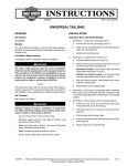
-J05592
REV. 2012-07-24
SPORTSTER MUSTACHE ENGINE GUARD
GENERAL
is01085
Kit Number
49000005 (chrome), 49000006 (black)
3
Models
1
For model fitment information, see the P&A Retail Catalog or
the Parts and Accessories section of www.harley-davidson.com
(English only).
2
The front and/or rear guard(s) can provide limited leg and
cosmetic vehicle protection under unique circumstances.
(Fall over while stopped, very slow speed slide.) It is not
made or intended to provide protection from bodily injury
in a collision with another vehicle or any other object.
(00022a)
NOTE
1. Tie-Link mounting bracket (shown without horn
mounting bracket)
2. Screws with washers
3. Threaded crossmember (upper)
A service manual for your model motorcycle is available from
a Harley-Davidson Dealer.
Kit Contents
See Figure 5 and Table 1.
Figure 1. Remove upper Tie-Link to Frame Hardware (XL
1200 Custom Shown
INSTALLATION
NOTES
is01086
Cover front fender with a clean rag to protect it from scratches
during installation procedures.
When performing the following steps you may also be removing
the horn mounting bracket.
1.
Models with horn mounted between down tubes: Note
location of horn wires and remove the two horn connectors
from the back of the horn.
1
1. Threaded crossmember
Figure 2. Lower Frame (threaded) Crossmember
2.
-J05592
See Figure 1. Remove the two screws with washers (2)
securing the upper tie-link assembly (1) and horn bracket
if present to the upper front frame crossmember (3). Leave
tie-link assembly in position. Discard screws and washers.
Many Harley-Davidson® Parts & Accessories are made of plastics and metals which can be recycled.
Please dispose of materials responsibly.
1 of 3
3.
See Figure 5. Obtain two 3/8-16 X 1-1/2 inch screws (1),
two flat washers (3) and engine guard from kit (4).
is01087
NOTE
For Step 4, note that upper section of engine guard must be
mounted between horn bracket and upper tie-link bracket. See
Figure 3 noting that illustration does not show the horn
mounting bracket.
4.
Figure 3 illustrates mounting without horn bracket and
horn in place. Place flat washers on screws. Obtain horn
bracket with horn if present. While holding engine guard
and horn bracket in place at upper crossmember, install
screws with washers (2) through horn bracket, upper
engine guard mount (1), tie-link mounting bracket and
thread into holes in upper frame crossmember. Tighten
just enough to hold the assembly snug and in place.
5.
See Figure 5. Obtain two 3/8-16 X 3/4 inch screws (2) and
two flat washers from kit (3).
6.
See Figure 4. Install flat washers onto screws. Install
screws (2) through lower engine guard mount (1) holes
and thread into lower crossmember holes. Tighten until
snug only.
7.
By sight, carefully center the engine guard and hold in
position.
8.
Tighten the upper mounting screws to 25-35 ft-lbs (34-47
Nm).
9.
Tighten the lower mounting screws to 25-35 ft-lbs (34-47
Nm).
1
2
1. Upper engine guard mount
2. Screws and washers
Figure 3. Mount Upper Section of Engine Guard
is01089
1
10. Turn handlebars fully to the right and left and inspect for
adequate clearance between the engine guard and the
clutch and brake cables.
2
1. Lower engine guard mount
2. Screws and washers
Figure 4. Mount Lower Section of Engine Guard
-J05592
2 of 3
SERVICE PARTS
is07398
3
1
4
3
2
Figure 5. Sportster Mustache Engine Guard
Table 1. Service Parts Table
Item
Description (Quantity)
Part Number
1
Screw, 3/8-16 x 1-1/2 inch (2)
4721
2
Screw, 3/8-16 x 3/4 inch (2)
4713W
3
Washer, flat 3/8 inch (4)
6026
4
Assembly, engine guard (chrome)
Assembly, engine guard (black)
Not Sold Separately
Not Sold Separately
5
Foot pad service kit (not shown)
49000034
-J05592
3 of 3