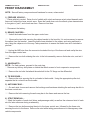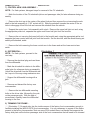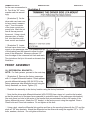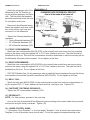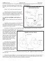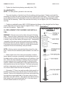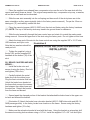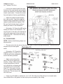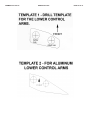
1
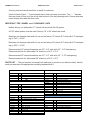
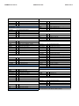
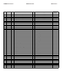
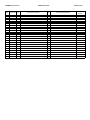
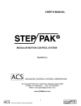
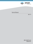
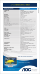
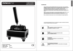
FORM#3570.01-021114 PRINTED IN U.S.A. PAGE 1 OF 21 SUPERLIFT 8” LIFT SYSTEM for 2014 1/2-ton Chevrolet Silverado and GMC Sierra 2WD and 4WD INSTALLATION INSTRUCTIONS INTRODUCTION Installation requires a professional mechanic. Prior to beginning, inspect the vehicles steering, driveline, and brake systems, paying close attention to the suspension link arms and bushings, anti-sway bars and bushings, tie rod ends, pitman arm, ball joints and wheel bearings. Also check the steering sector-to-frame and all suspension-to-frame attaching points for stress cracks. The overall vehicle must be in excellent working condition; repair or replace all worn parts. Read instructions several times before starting. Be sure you have all needed parts and know where they install. Read each step completely as you go. NOTES: Prior to beginning the installation, check all parts and hardware in the box with the parts list below. If you find a packaging error, contact Superlift directly. Do not contact the dealer where the system was originally purchased. You will need the control number from each box when calling; this number is located at the bottom of the part number label and to the right of the bar code. Do not fabricate any components to gain additional suspension height. A special tool is required to disassemble / assemble the front struts. Other special tools are recommended to detach/attach the pitman/idler studs. Refer to the factory service manual. Front end realignment is necessary. An arrow on diagrams indicates which direction is toward the front of the vehicle. A foot-pound torque reading is given in parenthesis ( ) after each appropriate fastener. Prior to drilling or cutting, check behind the surface being worked on for any wires, lines, or hoses that could be damaged. After drilling, file smooth any burrs and sharp edges. Prior to operating a torch or saw, protect any heat-sensitive components located in the immediate area by covering them with a water-saturated cloth. Most undercoating are flammable but can be extinguished using a water-filled spray bottle. Have a spray bottle and an ABC rated fire extinguisher on hand. Paint or undercoat all exposed metal surfaces. Prior to attaching components, be sure all mating surfaces are free of grit, grease, undercoating, etc. FORM#3570.01-021114 PRINTED IN U.S.A. PAGE 2 OF 21 A factory service manual should be on hand for reference. Use the check-off box “” found at each step to help you keep your place. Two “” denotes that one check-off box is for the driver side and one is for the passenger side. Unless otherwise noted, always start with the driver side. IMPORTANT TIRE / WHEEL and CLEARANCE DATA Neither factory nor aftermarket 17” wheels will work with this lift system. A 0.25” wheel spacer must be used if factory 18” or 20” wheels are used. Maximum tire diameter and width for use on the factory 18” wheel (8.5” wide with 5.3” backspacing) is 34.0” x 10.50”. Maximum tire diameter and width for use on the factory 20” wheel (9.0” wide with 6.0” backspacing) is 35.0” x 12.50”. Recommended 18” wheel dimensions are 8.0” - 8.5” wide with 4.5” - 5.0” backspacing. Recommended tire for aftermarket 18” wheels is a 34.0” x 10.5” Recommended 20” wheel dimensions are 8.0” - 9.5” wide with 4.5” - 5.75” backspacing. Recommended tire for aftermarket 20” wheels is a 35.0” x 12.5” PARTS LIST … The part number is stamped into each part or printed on an adhesive label. Identify each part and place the appropriate mounting hardware with it. Kit Part Number Component 66-01-3570 66-02-3570 77-3491 Kit Part Number Component 66-41-3570 66-42-3570 77-3491 Kit Part Number Component 55-03-3500 55-04-3570 55-06-3500 55-09-3500 55-10-3370 55-29-3480 66-15-3330 77-3500-2 77-3482B 77-3572 3570 Qty 1 1 1 Kit Part Number Component Description Knuckle, Dr Side 8" Chevy, AL OE LCA Knuckle, PA Side 8" Chevy, AL OE LCA Hardware Bag OR 3574 Qty 1 1 1 Component Description Knuckle, Dr Side 8" Chevy, MS OE LCA Knuckle, PA Side 8" Chevy, MS OE LCA Hardware Bag 3572 Qty 1 1 1 1 2 2 2 1 1 1 Component Description Brkt, Differential Drop - DR Side Brkt, Differential Drop - PA Side Brkt, Rear Crossmember Brkt, Belly Pan - 4wd Front Kicker Brace Brkt Kicker Brace Mach, Axle Spacer Hardware Bag Hardware Bag Hardware Bag Component 413017 01-85160 01-88150 55-05-3570 55-07-3500 55-08-3500 55-12-3500 66-10-3500 77-3451 77-3486 77-3488A 77-3500 77-80033 Kit Part Number Component 059 10542 01-2600 77-1509 77-38500 3571 Qty 2 2 2 1 1 1 2 2 1 1 1 1 1 Component Description Urethane bump stop for strut Shock Cylinder Shock Cylinder-Gas Strut Brkt, Front Crossmember Brkt, Sway Bar Drop Driver Brkt, Sway Bar Drop Passenger Front Strut Spacer for 8" kit Rear Bump stop Spacer Aluminum- Machined Hardware Bag, Chevy Strut Hardware Bag Hardware Bag Hardware Bag Shock Hardware Bag 3503 Qty 2 4 2 1 1 Component Description Rear Lift Block 5" U-Bolt, 9/16" X 2-1/2" X 14" Sq Add-A-Leaf, GM Pickup 9/16" Hi-Nut & Flat Washer Kit 3/8" Tie Bolt Hardware Bag FORM#3570.01-021114 Kit Part Number Component 1509 1559 Kit Part Number Component 38X212C5CS 38UW 38C5NN 10MNN Kit Part Number Component 01-2210 12-3370 31-3480 716C8SN 716SW 716X114C5CS 716X112C5CS 716X334C5CS Kit Part Number Component 14C5NN 14X34C5CS 55-13-3480 55-14-3480 Kit Part Number Component 10MFW 10MNN 10MX1.5X25CS 1112CT 58C8SN 58SW 58X412C5CS Kit Part Number Component 516X1STB F470L PRINTED IN U.S.A. 77-1509 Qty Component Description 8 HI-Nut, 9/16" Fine 8 9/16" U-Bolt Flat washer 77-3451 Qty 4 8 4 2 Component Description Bolt, 3/8" X 2.5" Coarse Flat Washer, 3/8" USS Nyloc Nut, 3/8" Coarse Nyloc Nut, 10mm X 1.5 77-3482B Qty 8 4 2 4 12 2 1 4 Component Description Poly Bush,T-Bar Sm. Eye Sleeve - 0.75" X 0.46875" X 2.625" 7/16" Tab Nut Stover Nut, 7/16" Coarse Flat Washer, 7/16" SAE Bolt, 7/16 X 1-1/4 Coarse Bolt, 7/16 X 1-1/2 Coarse Bolt,7/16 X 3-3/4 Coarse 77-3486 Qty 2 2 1 1 Component Description Nyloc Nut, 1/4" Coarse Bolt, 1/4" X 3/4" Coarse Brkt, Frt Brake line Dr Brkt, Frt Brake line Pa 77-3488A Qty 8 4 4 2 2 4 2 Component Description Washer, 10mm Flat Nyloc Nut, 10mm X 1.5 Bolt, 10mm X 1.5 X 25mm Cable Tie, 11-1/2" Black Stover Nut, 5/8" Coarse Flat Washer, 5/8" SAE Bolt, 5/8" X 4-1/2" Coarse 77-3491 Qty Component Description 2 Bolt, 5/16" X 1" Self Tapping 1 Thread Locker #27105 Kit Part Number Component 10MFW 10MX1.5X180AS 13-3500 16MDN 716F8SFN Kit Part Number Component 58C8SN 58SW 58X512C5CS Kit Part Number Component 10MFW 10MX1.5X70CS 12C8SN 12MLW 12MX1.75X30CS 12SW 12X134C5CS 16-9690 17-9690 58C8SN 58X134C5CS 58SW 1555 38X1C5CS 38SW 38C5NN Kit Part Number Component 01-38500 38F5N Kit Part Number Component 01-60418 34SW 39-3480 PAGE 3 OF 21 77-3500 Qty 2 2 1 1 6 Component Description Washer, 10mm Flat Bolt, Allen Head 10mm x 1.5 x 180mm 3/16" ID X 3/8" OD Tubing 8" Long, Vacuum 16mm x 1.5 Hex Die Nut Flange Nut, 7/16" Fine 77-3500-2 Qty 2 4 2 Component Description Stover Nut, 5/8" Coarse Flat Washer, 5/8" SAE Bolt, 5/8" X 5-1/2" Coarse 77-3572 Qty 12 12 2 2 2 4 2 1 1 2 2 4 2 4 8 4 Component Description Washer, 10mm Flat Bolt, 10mm X 1.5 X 70mm Stover Nut, 1/2" Coarse Lock Washer, 12mm Bolt,12mm X 1.75 X 30mm Flat Washer, 1/2" SAE Bolt,1/2" X 1-3/4" Coarse 3/16" ID X 3/8" OD Tubing 4" Long, Vacuum 3/16" Vacuum Connector Stover Nut, 5/8" Coarse Bolt, 5/8" x 1-3/4" Coarse Flat Washer, 5/8" SAE 5/8" U-Bolt Flat washer Bolt, 3/8" X 1" Coarse Flat Washer, 3/8" SAE Nyloc Nut, 3/8" Coarse 77-38500 Qty Component Description 2 Tie Bolt 3/8" X 5" 2 Std. Nut, 3/8" Fine 77-80033 Qty 4 4 4 Component Description Poly Bush, 3/4" X 1.44" Sm. Hourglass Eye Washer, 3/4" Flat Sae Shock Sleeve, 0.750" OD x 0.563" ID x 1.68" L ITEMS HIGHLIGHTED IN GREY ARE NOT USED IN THIS KIT. FORM#3570.01-021114 Step Component Qty. PRINTED IN U.S.A. Component Description Qty. New Attaching Hardware 1 Bolt, 5/16" X 1" Self Tapping 0.5 Thread Locker #27105 PAGE 4 OF 21 Hardware Bag Number 77-3491 17 66-01-3570 or 17 66-41-3570 1 Knuckle, Dr Side 8" Chevy, AL OE LCA 1 Knuckle, Dr Side 8" Chevy, MS OE LCA 17 66-02-3570 or 17 66-42-3570 1 Knuckle, PA Side 8" Chevy, AL OE LCA 1 Knuckle, Dr Side 8" Chevy, MS OE LCA 10 55-03-3500 1 Brkt, Differential Drop - DR Side 2 2 2 2 2 Bolt,1/2" X 1-3/4" Coarse Bolt,12mm X 1.75 X 30mm Flat Washer, 1/2" SAE Lock Washer, 12mm Stover Nut, 1/2" Coarse 77-3572 10 55-04-3570 1 Brkt, Differential Drop - PA Side 1 1 2 2 3/16" ID X 3/8" OD Tubing 4" Long, Vacuum 3/16" Vacuum Connector 5/8" U-Bolt Flat washer Stover Nut, 5/8" Coarse 77-3572 11 55-05-3570 1 Brkt, Front Crossmember 2 4 2 Bolt, 5/8" X 4-1/2" Coarse Flat Washer, 5/8" SAE Stover Nut, 5/8" Coarse 77-3488A 12 55-06-3500 1 Brkt, Rear Crossmember 2 4 2 Bolt, 5/8" X 5-1/2" Coarse Flat Washer, 5/8" SAE Stover Nut, 5/8" Coarse 77-3500-2 22 55-07-3500 1 Brkt, Sway Bar Drop Driver 2 2 4 Bolt, 10mm X 1.5 X 25mm Nyloc Nut, 10mm X 1.5 Washer, 10mm Flat 77-3488A 22 55-08-3500 1 Brkt, Sway Bar Drop Passenger 2 2 4 Bolt, 10mm X 1.5 X 25mm Nyloc Nut, 10mm X 1.5 Washer, 10mm Flat 77-3488A 13 55-09-3500 1 Brkt, Belly Pan - 4wd 4 8 4 Bolt, 3/8" X 1" Coarse Flat Washer, 3/8" SAE Nyloc Nut, 3/8" Coarse 77-3572 23 55-10-3370 2 Front Kicker Brace Brkt 1 1 1 7/16" Tab Nut Bolt, 7/16 X 1-1/4 Coarse Flat Washer, 7/16" SAE 77-3482B 29 66-10-3500 2 Rear Bump stop Spacer Aluminum- Machined 1 1 1 3/16" ID X 3/8" OD Tubing 8" Long, Vacuum Bolt, Allen Head 10mm x 1.5 x 180mm Washer, 10mm Flat 77-3500 19 55-12-3500 2 Front Strut Spacer for 8" kit 3 Flange Nut, 7/16" Fine 77-3500 20 55-13-3480 1 Brkt, Frt Brake line Dr 1 1 Nyloc Nut, 1/4" Coarse Bolt, 1/4" X 3/4" Coarse 77-3486 1 Bolt, 5/16" X 1" Self Tapping 0.5 Thread Locker #27105 77-3491 FORM#3570.01-021114 PRINTED IN U.S.A. Step Component Qty. Component Description Qty. PAGE 5 OF 21 New Attaching Hardware Hardware Bag Number 77-3486 20 55-14-3480 1 Brkt, Frt Brake line Pa 1 1 Nyloc Nut, 1/4" Coarse Bolt, 1/4" X 3/4" Coarse 18 66-15-3330 2 Mach, Axle Spacer 6 6 Bolt, 10mm X 1.5 X 70mm Washer, 10mm Flat 77-3572 23 55-29-3480 2 Kicker Brace 2 4 4 2 2 Bolt,7/16 X 3-3/4 Coarse Flat Washer, 7/16" SAE Poly Bush,T-Bar Sm. Eye Sleeve - 0.75" X 0.46875" X 2.625" Stover Nut, 7/16" Coarse 77-3482B 19 01-88150 2 Shock Cylinder-Gas Strut 2 4 1 2 1 Bolt, 3/8" X 2-1/2" Coarse Flat Washer, 3/8" USS Nyloc Nut, 10mm X 1.5 Nyloc Nut, 3/8" Coarse Urethane bump stop for strut 77-3451 31 01-85160 2 Shock Cylinder 2 2 2 Poly Bush, 3/4" X 1.44" Sm. Hourglass Eye Shock Sleeve, 0.750" OD x 0.563" ID x 1.68" L Washer, 3/4" Flat Sae 77-80033 30 01-2600 2 Add-A-Leaf, GM Pickup 1 1 Tie Bolt 3/8" X 5" Std. Nut, 3/8" Fine 77-38500 31 059 2 Rear Lift Block 5" 2 4 4 U-Bolt, 9/16" X 2-1/2" X 14" Sq HI-Nut, 9/16" Fine 9/16" U-Bolt Flat washer 77-1509 FORM#3570.01-021114 FRONT DISASSEMBLY PRINTED IN U.S.A. PAGE 6 OF 21 NOTE: Save all factory components and hardware for reuse, unless noted. 1) PREPARE VEHICLE... Place vehicle in neutral. Raise front of vehicle with a jack and secure a jack stand beneath each frame rail, behind the lower control arms. Ease the frame down onto the stands, place transmission in low gear or “park”, and chock rear tires. Remove front tires. Disconnect the battery. 2) BRAKE CALIPERS… Unbolt the brake hoses from the upper control arm. Remove the two bolts securing the caliper bracket to the knuckle. It is not necessary to remove the caliper from the bracket. Leave the brake hose attached to the caliper, and using mechanic’s wire, hang the calipers out of the way. Take precautions to ensure the brake hose isn’t stretched or pinched. Unplug the ABS wire from the connector located at the top of the frame rail and unclip the wire from the upper control arm. Remove the torx bolt retaining the rotor to the hub assembly, remove the brake rotor, and set it aside. 3) AXLESHAFTS… NOTE: For 2wd systems, proceed to the next step. Remove any factory skid plates or shields that block access to front suspension components. Remove the six bolts that attach the axleshaft to the CV flange on the differential. 4) TIE ROD ENDS… Remove the nuts securing the tie rod ends to the knuckle. Using the appropriate puller tool, separate the tie rod end from the knuckle. 5) ANTI-SWAY BAR… On each side, loosen and remove the bushings and hardware attaching the anti-sway bar link to the lower control arm. Remove the bolts securing the anti-sway bar to the frame and remove the bar. 6) STRUT REMOVAL… Mark the location of each strut (driver and passenger side) as well as the outermost stud of each strut for later reference during re-assembly. Remove the two bolts securing the strut to the lower control arm, followed by the three nuts securing the strut to the frame. Remove the strut while taking precautions not to damage any other vehicle components. FORM#3570.01-021114 PRINTED IN U.S.A. PAGE 7 OF 21 7) CONTROL ARM / HUB ASSEMBLY… NOTE: For 2wd systems, disregard steps for removal of the CV axleshafts. Mark the location of the CV axleshafts (driver and passenger side) for later reference during assembly. Remove the dust cap in the center of the wheel hub and then remove the nut securing the axleshaft to the hub assembly (a 1-3/8” socket will fit). Slide the axleshaft towards the center of the vehicle to disengage it from the hub and remove the axleshaft from the vehicle. Support the control arm / hub assembly with a jack. Remove the upper ball joint nut and, using the appropriate puller tool, separate the upper control arm ball joint from the knuckle. Remove the nut securing the lower ball joint to the knuckle and, using the appropriate puller tool, separate the lower control arm ball joint from the knuckle. Set the knuckle, with the wheel bearing assembly still attached, aside. Remove the bolts securing the lower control arm to the frame and set the lower control arm aside. 8) DIFFERENTIAL… NOTE: For 2wd systems, proceed to the next step. Illustration 1 Remove the electrical plug and vent hose from the differential. Mark the driveshaft in relation to the differential yoke for reference during re-assembly. Unbolt the driveshaft from the differential and tie it up out of the way using mechanics wire. Support the differential housing with a jack. Remove and discard the factory rear crossmember. Remove the two differential mounting bolts on the driver side, followed by the nuts on the passenger side. With the help of an assistant, carefully lower the differential housing to the floor. 9) TRIMMING THE FRAME… [Illustration 1] On each side, trim the inside corners of the factory front crossmember enough to facilitate installing the (#55-05-3570) front crossmember. It is only necessary to square off the radius present in the factory crossmember. Note on some 2014 models there is a bracket that supports the factory skid plate on the bottom passenger side of the front crossmember that will need to be trimmed FORM#3570.01-021114 PRINTED IN U.S.A. PAGE 8 OF 21 for the new crossmember to Illustration 2 fit. Test fit the “05” crossmember and trim accordingly. [Illustration 2] On the driver side rear lower control arm mount, measure over 1” from the center of the lower control arm mount hole. Mark the cut line all the way around the mount. Using a torch, plasma cutter, or similar tool, trim the driver side lower control arm bracket. [Illustration 3] Locate the rear lower control arm mount on the passenger side. The forward side lip Illustration 3 of this bracket must be trimmed to allow for clearance of the differential. Measure outboard 1/2” from the edge of the outermost bolt hole and mark. Trim just above the lip to this mark as shown in the Illustration. FRONT ASSEMBLY 10) DIFFERENTIAL BRACKETS… NOTE: For 2wd systems, proceed to the next step. [Illustration 4] Remove the factory passenger side “u” shaped differential bracket. Attach passenger side differential bracket (#55-04-3570) to the factory passenger side differential mount using the factory hardware, as shown. Tighten (75). Reattach the assembly to the factory location using the factory hardware. Note that the driver side differential bracket (#55-03-3500) has a taper in it; position the bracket so that the small end of the taper faces rearward (to match the taper of the passenger side bracket). Also note there is a hole in the center of the bracket that accommodates a tab in the center of the factory differential mount. Attach the “03” bracket to the factory mount using the supplied 12mm x 30mm bolts and 12mm lock washers. Do not tighten at this time. Using a jack, raise the differential into position and line up the mounting holes with the “03” and the studs on “04” drop brackets. Attach the differential on the driver side using the supplied 1/2” x 1-3/4” bolts, washers, and nuts. Do not tighten at this time. FORM#3570.01-021114 PRINTED IN U.S.A. PAGE 9 OF 21 Attach the passenger side of the Illustration 4 differential to the “04” bracket using the supplied washers, and Nyloc nuts. The extra-thick flat washers should be positioned under the nuts. Do not tighten at this time. Reconnect the differential wiring. Attach the supplied vent hose extension to the factory vent hose and reconnect it to the differential. Tighten the following hardware in sequence: 12mm differential hardware (87) 1/2” differential hardware (76) 5/8” differential hardware (150) 11) FRONT CROSSMEMBER… Attach the front crossmember (#55-05-3570) to the original lower control arm front leg mounting points on the frame using the supplied 5/8” x 4-1/2” bolts, washers, and nuts. The bolts should be installed from the front. Note that the crossmember should be positioned so that the mounting tab for the differential skid plate points rearward. Do not tighten at this time. 12) REAR CROSSMEMBER… Attach the rear crossmember (#55-06-3500) to the original lower control arm rear leg mounting points on the frame using the supplied 5/8” x 5-1/2” bolts, washers, and nuts. The bolts should be installed from the front. Do not tighten at this time. 2007-2013 Models Only: On the passenger side re-install the factory hardware through the factory crossmember hole and the Superlift crossmember (#55-06-3500). Do not tighten at this time. 13) BELLY PAN… Attach the belly pan (#55-09-3500) to the mounting tabs on the front and rear crossmembers using the supplied 3/8” x 1” bolts, washers (at head and nut), and Nyloc nuts. Tighten (30). 14) FASTENER TIGHTENING SEQUENCE… Tighten the 5/8” crossmember hardware (154). 15) DRIVESHAFT… NOTE: For 2wd systems, proceed to the next step. Line up the front driveshaft with the differential yoke according to the marks made during removal and secure using the factory hardware. Tighten (18). 16) LOWER CONTROL ARMS… [Illustration 5 and Template 1 or 2 on last page] Template 1 is for all steel lower control arms. Template 2 is for all aluminum lower control arms. Cut out the supplied template attached to the FORM#3570.01-021114 PRINTED IN U.S.A. PAGE 10 OF 21 end of this instruction form. Line up the template with the existing anti-sway bar link mounting hole as shown. Scribe the location of the new hole to Illustration 5 be drilled (which should be inboard of the existing hole). Drill an 11/16” hole at the scribed location. Attach the lower control arm to the front and rear crossmembers using the factory hardware. The bolts should be installed from the front. Snug, but do not tighten the hardware at this time. 17) KNUCKLE ASSEMBLY AND INSTALLATION… NOTE: Perform these steps on one knuckle at a time. Carefully note the orientation of the dust shield and wheel bearing assembly prior to removal. Remove the three bolts securing the wheel bearing assembly to the factory knuckle. [Illustration 6] Remove the dust shield and wheel bearing assembly from the factory knuckle. Now test-fit the dust shield on the new knuckle (#66-01-3570 driver Illustration 6 side and #66-02-3570 passenger side; or #66-41-3570 driver side and #66-42-3570 passenger side). Mark the area of the dust shield to be trimmed as shown. Remove the dust shield and trim at the marked location using a cut-off wheel or similar tool. Install the bearing assembly and dust shield on the Superlift knuckles using the factory hardware. Be sure the orientation of the dust shield and bearing assembly matches original. Use the supplied thread-locking compound on the three factory fasteners Install the knuckle assembly and secure using the factory nuts. Tighten the upper nut (37) and lower nut (94). Check-fit the brake caliper to be sure enough material has been removed from the dust shield. If interference is evident, mark the area on the dust shield, remove the wheel bearing and dust shield from the knuckle, and trim until the necessary clearance is achieved. FORM#3570.01-021114 PRINTED IN U.S.A. PAGE 11 OF 21 Tighten the three factory bearing assembly bolts (133). 18) AXLESHAFTS… NOTE: For 2wd systems, proceed to the next step. Turn each knuckle so that the front of the knuckle is pointing outward. Position and install the axleshafts according the marks made during removal (Driver and Passenger). This is done by passing the differential end of the axleshaft in front of the differential housing and then sliding the shaft through the hub assembly. Secure the shaft with the factory nut and tighten (148-165). Reattach the dust cap. Position an axleshaft spacer (#66-15-3330) between the flange on the axleshaft and the flange on the differential and secure using the supplied 10mm x 70mm Illustration 7 bolts and flat washers. Tighten (58). 19) REPLACEMENT STRUT ASSEMBLY AND INSTALLATION… WARNING: Extreme care must be taken during the following steps. The struts have a tremendous amount of energy stored in them and can cause serious injury or even death if an attempt is made to work on them without the proper tools. Disassembly / assembly of the struts can only be performed by a qualified professional with the special equipment designed for this task. If necessary, the struts can be taken to a shop with the proper equipment to have the necessary work performed. NOTE: A factory service manual should be on hand for reference. Perform the strut assembly and installation one side at a time. Make careful note of the order and orientation of all the factory pieces for proper re-assembly, including the position of the upper studs in relation the large bar pin at the bottom of the strut. Place the strut assembly in a heavy-duty strut compressor and compress the coil spring enough to unload the strut cylinder. Remove the retaining nut on the upper shock mount and carefully remove the strut cylinder. The lower spring seat and foam compression stop should come out with the strut; if not, remove these items from the coil assembly. [Illustration 7] There is a metal cap with a light press fit on the body of the factory strut; tap the cap off of the strut with a hammer. Remove the retaining ring and lower spring seat from the original strut and install them in the same order on the replacement strut (#01-88150). Take special note that the factory lower spacer has a groove machined into it; the snap ring on the strut should recess into this groove. FORM#3570.01-021114 PRINTED IN U.S.A. PAGE 12 OF 21 Place the supplied cone-shaped foam compression stop over the rod of the new strut with the narrow end facing down as shown. The original compression stop, compression stop cup, or washer, will not be re-used and can be discarded. Slide the new strut assembly into the coil spring and be sure all of the strut pieces are in the same orientation as they were originally (refer to the factory service manual). Torque the 10mm retaining nut (37) and carefully unload the strut. Place the new strut spacer (#55-12-3500) onto the strut and fasten using the factory hardware (37). NOTE: The top of the factory studs may need to be ground down for clearance. Slide the strut assembly through the lower control arm and rotate it to match the marks made during removal. Secure the upper end of the strut using the factory nuts. Do not tighten at this time. Attach the lower end of the strut to the lower control arm using the supplied 3/8” x 2-1/2” bolts, USS washers, and Nyloc nuts. Illustration 8 Note that two washers should be used per bolt. Tighten the supplied nuts at the top (50) and the supplied 3/8” hardware at the bottom (30) of the strut. 20) BRAKE CALIPERS AND ABS WIRING… Install the brake rotor and secure it using the factory Torx bolt and tighten (106 in-lbs). Carefully detach the metal brake line from the rubber hose. Plug the line to minimize fluid loss. Unbolt the brake hose bracket at the frame that secures the connection between the rubber hose and the steel line. Detach the bracket from the hose and discard. Spread apart the clamped portion of the bracket that attached the brake hose to the upper control arm and discard the bracket. [Illustration 8] Attach the brake hose relocation bracket (#55-13-3480 driver side and #55-143480 passenger side) to the factory brake hose location on the frame. Secure using the factory hardware and tighten (76 in-lbs). Make sure the relocation bracket is level with the frame. Using the bracket as a template, drill the second mounting hole as shown using a 1/4” bit. Install the supplied 1/4” x 3/4” bolt and Nyloc FORM#3570.01-021114 nut. Tighten (76 in-lbs). PRINTED IN U.S.A. PAGE 13 OF 21 Illustration 9 Line up the rubber brake hose with the hole in the new bracket and carefully reform the metal line to reach the rubber hose’s new location. Connect the metal line and tighten to factory specifications. Attach the caliper bracket assembly to the knuckle. Apply the supplied thread-locking compound to the factory caliper bracket bolts and tighten (129). Be sure that the brake hose routing is exactly as shown in the Illustration. [Illustration 9] Route the ABS wiring exactly as shown in the Illustration. Secure the wire to the tab on the knuckle as well as the upper control arm using the supplied zip ties. Reconnect the wiring at the frame. 21) TIE ROD ENDS… NOTE: Perform the following steps one side at a time. The jam nut for the tie rod end should have been loosened during disassembly. Remove the end and jam nut; set these parts Illustration 10 aside. [Illustration 10] Thread the supplied 16mm x 1.5 die nut on to the tie rod until it reaches the end of the factory threads. Apply some cutting lubricant to the tie rod (male end) and die. Using a 16mm wrench on the flats present in the tie rod, hold the tie rod steady and use the die nut to cut an additional 1/2” of threads on the tie rod, or the approximate width of the die nut. Do not remove the die at this time. Using a cut-off wheel or similar tool, cut 1-1/4” off of the end of the factory tie rod (male end). Use a thread file or die grinder to clean up any burrs caused by the cutting. FORM#3570.01-021114 PRINTED IN U.S.A. PAGE 14 OF 21 Unscrew the die nut from the tie rod, using it to “chase” the threads on the end of the tie rod where it was cut. The die should thread smoothly on and off the end of the rod. Reinstall the factory jam nut, followed by the tie rod end. Final toe adjustments will take place once the suspension installation is complete. Snug the jam nut for now. Attach the tie rod end to the knuckle using the factory nut and tighten (44). Repeat these steps on the other side of the vehicle. 22) ANTI-SWAY BAR… Attach the anti-sway bar drop brackets (#55-07-3500 driver side and #55-08-3500 passenger side) to the factory sway bar mounts on the frame using the supplied 10mm x 25mm bolts and flat washers. Note that the lower end of the brackets should be offset toward the rear of the vehicle, and that the C-shaped brackets should be pointed toward the center of the vehicle. Do not tighten at this time. Attach the anti-sway bar to the drop brackets using the factory bolts, supplied 10mm flat washers, and supplied 10mm Stover nuts. Do not tighten at this time. Position a bushing on the lower end of the anti-sway bar links, then insert the link in the hole of the lower control arm that was drilled previously. Install the remaining bushings and hardware, and tighten until the bushings swell slightly. Tighten the remaining 10mm hardware (50). 23) KICKER BRACES… Remove the transfer case skid plate attached to the transmission crossmember. It will need to be trimmed once the kicker braces are installed. Install the bushings and sleeves in the ends of the kicker braces (#55-29-3480). Position one end of each brace in the front bracket tabs and loosely secure using the supplied 7/16” x 3-3/4” bolts, washers, and Stover nuts. Do not tighten at this time. Loosely attach the rear kicker brace mounts (#55-10-3370) to the other end of the kicker braces using the supplied 7/16” x 3-3/4” bolts, washers, and Stover nuts. Swing the kicker braces up to the transmission crossmember and line up the mounting holes in the “10” brackets with the existing holes in the transmission crossmember. Secure the brackets to the crossmember using the supplied 7/16” x 1-1/4” bolts, SAE washers, and tab nuts. Tighten all of the 7/16” kicker brace hardware (50). Test-fit the transfer case skid plate to determine where it should be trimmed to clear the driver side kicker brace bracket. Trim the skid plate as necessary and re-install it on the transmission crossmember using the factory hardware (15). 24) TIRES / WHEELS... [Illustration 11] Tighten the lug nuts (140) in the sequence shown. WARNING: When the tires / wheels are installed, always check for and remove any corrosion, dirt, or foreign material on the wheel mounting surface, or anything that contacts the wheel mounting surface FORM#3570.01-021114 PRINTED IN U.S.A. PAGE 15 OF 21 (hub, rotor, etc.). Installing wheels without the proper metal-to-metal contact at the wheel mounting surfaces can cause the lug nuts to loosen and the wheel to come Illustration 11 off while the vehicle is in motion. WARNING: Retighten lug nuts at 500 miles after any wheel change, or anytime the lug nuts are loosened. Failure to do so could cause wheels to come off while vehicle is in motion. 25) CLEARANCE CHECK... With the vehicle still on jack stands, and the suspension “hanging” at full extension travel, cycle steering lock-to-lock and check all components for proper operation and clearances. Pay special attention to the clearance between the tires / wheels and brake hoses, wiring, etc. Lower vehicle to the floor. 26) FINAL HARDWARE TIGHTENING… Tighten the lower control arm bolts (129). REAR PROCEDURES 27) PREPARE VEHICLE... Illustration 12 Raise rear of vehicle with a floor jack positioned under the rear axle. Place jack stands under the frame rails, a few inches in front of the rear springs’ front hangers. Ease the jack down until the frame is resting on the stands. Keep a slight load on the jack. Chock front tires to prevent accidental movement. Remove the tires. Remove the shock absorbers. 28) REAR BRAKE LINES... Unbolt the rear brake hose bracket from the top of the driver side frame rail. This bracket secures the connection between the metal brake lines and rubber hoses from the frame. [Illustration 12] Carefully reform the metal lines so that the mounting foot for the bracket lines up with the bottom of the frame rail, directly below its original attachment point. Use extreme caution to avoid pinching or otherwise damaging the lines. Using the bracket as a template, mark the location of the new mounting holes to be drilled in the bottom of the frame. Move the brake lines out of harm’s way and drill at the marked locations using a 17/64” bit. FORM#3570.01-021114 PRINTED IN U.S.A. PAGE 16 OF 21 Line up the bracket with the drilled holes and install the supplied 5/16” x 1” self-tapping bolts. Tighten (13). Unbolt the compression stops from their mounting cups. Discard the hardware but save the stops for re-use. REAR DISC BRAKE MODELS ONLY… Disconnect the driver side emergency brake cable from brake adjuster at the frame. Route the cable over the axle tube and then re-attach it to the caliper. Re-attach to the caliper and check for proper operation. On the driver side lower shock mount there is a clamp that secures the driver side emergency brake cable to the axle. Unbolt the clamp, move to the axle pad and attach using the 5/16” x 1” bolt, washer, and flange nut. Reinstall the bolt securing the brake line and tighten to factory specifications. 29) SPRING PACK DISASSEMBLY… Remove spring to axle U-bolts and move axle several inches away from springs. Place C-clamps approximately six inches on either side of the leaf springs center bolt. Pinch the tie bolt head (the portion that was located in the spring perch) with a pair of pliers, then remove the tie bolt nut. Remove the roll pin from the overload leaf and discard. Once the nut has been removed, loosen the C-clamps. NOTE: Be cautious when releasing the C-clamps; the springs are under load and will “spring” apart when released. Position a factory compression stop on one end of the new compression stop spacer (#66-103500). Slide the supplied 10mm x 180mm bolt through the hole in the center of the compression stop and spacer, then thread the bolt into the factory mount on the frame. Tighten (50). 30) SPRING PACK ASSEMBLY… On each side, insert the add-a-leaf between the number one and number two leaf from the axle side, in the proper pyramid order. Align the 3/8” hole in the add-a-leaf with the center bolt hole in the spring pack. Recompress the pack with the Illustration 13 C-clamp, not the center bolt, to avoid stripping the bolt or nut threads. Once the spring is compressed, insert the 3/8” x 5” center bolt through the leaf spring pack. Tighten the center bolt nut (45). Once tightened, trim excess bolt. Remove the C-clamps. 31) LIFT BLOCKS AND SHOCK ABSORBERS... Clean spring pads of all debris. Position the Superlift block on top FORM#3570.01-021114 PRINTED IN U.S.A. PAGE 17 OF 21 of the factory block, then using the floor jack(s), mate the springs to Illustration 14 the blocks, be sure that the center bolt heads seat properly. Install the new Superlift U-bolts and factory U-bolt plate. Evenly torque the U-bolts using an “X” tightening sequence (85). Install the rear shock absorbers. Position a supplied 3/4” SAE washer at the top and bottom of the shock on the inside of the bracket and tighten the upper and lower bolts (76). 32) ABS WIRING AND FINAL CLEARANCE… Disconnect rear ABS plug located on the top of frame above the compression stops. Also, remove the two retaining clips from frame (one on top of frame and one on the bottom). Raise rear of vehicle so that the suspension is at full extension and place on jack stands. Holding the bottom retaining clip, pull the ABS wire trough the rubber grommet until there is enough slack that the wires are no longer in a bind at full extension. Reconnect ABS plug making sure not to bend the pins. Insert only the bottom retaining clip into the frame. The top retaining clip will remain loose. [Illustration 13] Pull the ABS wire up from the axle along the rear U-bolt and zip tie to U-bolt. 33) TIRES / WHEELS... [Illustration 14] Tighten the lug nuts (140) in the sequence shown. WARNING: When the tires / wheels are installed, always check for and remove any corrosion, dirt, or foreign material on the wheel mounting surface, or anything that contacts the wheel mounting surface (hub, rotor, etc.). Installing wheels without the proper metal-to-metal contact at the wheel mounting surfaces can cause the lug nuts to loosen and the wheel to come off while the vehicle is in motion. WARNING: Retighten lug nuts at 500 miles after any wheel change, or anytime the lug nuts are loosened. Failure to do so could cause wheels to come off while vehicle is in motion. 34) CLEARANCE CHECK... With the vehicle still on jack stands, and the suspension “hanging” at full extension travel, check all components for proper operation and clearances. Pay special attention to the clearance between the tires / wheels and brake hoses, wiring, etc. Lower vehicle to the floor. 35) BLEEDING THE BRAKE SYSTEM... Bleed the brake system following the procedure found in the factory service manual. 36) FOUR WHEEL DRIVE... Activate four wheel drive system and check front hubs for engagement. 37) HEADLIGHTS... FORM#3570.01-021114 PRINTED IN U.S.A. PAGE 18 OF 21 Readjust headlights to proper setting. 38) SUPERLIFT WARNING DECAL... Install the “WARNING TO DRIVER” decal on the inside of the windshield, or on the dash, within driver’s view. Refer to the “NOTICE TO DEALER AND VEHICLE OWNER” section below. 39) SUPERLIFT BADGES... This kit is packaged with a small Superlift badge for a location of your choosing and one large badge for the front crossmember. Prior to installation, use the supplied alcohol pad to eliminate all soap and or other non-adhering residues that may impair adhesion, thoroughly clean the entire area of placement. Remove the adhesive back and place the large badge on the front crossmember, using the holes for alignment. The adhesive on our badges is pressure sensitive and must be applied using pressure on all areas of the graphic. Like any PSA (pressure sensitive adhesive), it can take up to 72 hours for the adhesive to fully cure. Once the badge is in place do not peel it up, this will diminish the adhesive properties and could result in damaging the badge itself. Also included are two rivets to be used for extra security. To keep your Superlift badge in “like new” appearance keep the badge free/clear of solvents and chemicals that could cause the adhesive to dry or dissolve. This includes gasoline, diesel fuel, paint thinner, and alcohol. Soap and water is all that is needed for cleaning. Degreasers can be used sparingly and hand wiped / applied if needed, although not suggested. Important Maintenance Information It is the ultimate buyer’s responsibility to have all bolts / nuts checked for tightness after the first 100 miles and then every 1000 miles. The steering, suspension and driveline systems, plus wheel alignment should be inspected by a qualified professional mechanic at least every 3000 miles. Limited Lifetime Warranty / Warnings FORM#3570.01-021114 PRINTED IN U.S.A. PAGE 19 OF 21 Your Superlift® product is covered by the Limited Warranty explained below that gives you specific legal rights. This limited warranty is the only warranty Superlift® makes in connection with your product purchase. Superlift® neither assumes nor authorizes any retailer or other person or entity to assume for it any other obligation or liability in connection with this product or limited warranty. Superlift, LLC, Limited Lifetime Warranty What is covered? Subject to the terms below, Superlift® will repair or replace its products found defective in materials or workmanship for so long as the original purchaser owns the vehicle on which the product was originally installed. Your warrantor is Superlift, LLC, doing business as Superlift® Suspension Systems (“Superlift®”). What is not covered? Your Superlift® Limited Warranty does not cover products Superlift® determines to have been damaged by or subjected to: • Alteration, modification or failure to maintain. • Normal wear and tear (bushings, rod ends, etc.). Scratches or defects in product finishes (powder coating, plating, etc.). • Damage to, or resulting from, the vehicle’s electronic stability system, related components or other vehicle systems. • Racing or other vehicle competitions or contests. Accidents, impact by rocks, trees, obstacles or other aspects of the environment. • Theft, vandalism or other intentional damage. Remedy Limited to Repair or Replacement. The exclusive remedy provided hereunder shall, upon Superlift’s inspection and at Superlift’s option, be either repair or replacement of the product covered under this Limited Warranty. Customers requesting warranty consideration should contact Superlift® by phone (1-800-551-4955) to obtain a Returned Goods Authorization number. All removal, shipping and installation costs are customer’s responsibility. If a replacement part is needed before the Superlift® part in question can be returned, you must first purchase the replacement part. Then, if the part in question is deemed warrantable, you will be credited / refunded. Other Limitations - Exclusion of Damages - Your Rights Under State Law • Neither Superlift® nor your independent Superlift® dealer are responsible for any time loss, rental costs, or for any incidental, consequential or other damages you may have. • This Limited Warranty gives you specific rights, and this is the only warranty Superlift® makes in connection with your product purchase. You may also have other rights that vary from state to state. For example, while all implied warranties are disclaimed herein, any implied warranty required by law FORM#3570.01-021114 PRINTED IN U.S.A. PAGE 20 OF 21 is limited to the terms of our Limited Lifetime Warranty as described above. Some states do not allow limitations of how long an implied warranty lasts and / or do not allow the exclusion or limitation of incidental or consequential damages, so the limitations and exclusions herein may not apply to you. Superlift® neither assumes nor authorizes any retailer or other person or entity to assume for it any other obligation or liability in connection with this product or Limited Warranty. Superlift, LLC, Satisfaction Guarantee We want you to purchase our product with confidence and be 100% satisfied with the end result. If you have any legitimate issue, and Superlift® cannot rectify it to your satisfaction, Superlift® will take back the Superlift® brand product and refund the customer 100% of the product purchase price. The details: • Offer valid to the original retail consumer for six months after product purchase. • May require a Superlift® dealer’s participation in order to assist in “troubleshooting” the issue. • Any costs related to labor, freight, incidental or consequential are not refunded. • Refund will not exceed Superlift’s® published retail price. Important Product Use and Safety Information / Warnings As a general rule, the taller a vehicle is, the easier it will roll over. Offset, as much as possible, what is lost in rollover resistance by increasing tire track width. In other words, go “wide” as you go “tall”; always use as wide a tire and wheel combination as feasible to enhance vehicle stability. We strongly recommend, because of rollover possibility, that the vehicle be equipped with a functional roll bar and cage system. Seat belts and shoulder harnesses should be worn at all times. Avoid situations where a side rollover may occur. Generally, braking performance and capabilities are decreased when significantly larger / heavier tires and wheels are used. Take this into consideration while driving. Also, changing axle gear ratios or using tires that are taller or shorter than factory height will cause an erroneous speedometer reading. On vehicles equipped with an electronic speedometer, the speed signal impacts other important functions as well. Speedometer recalibration for both mechanical and electronic types is highly recommended. Do not add, alter, or fabricate any factory or aftermarket parts to increase vehicle height over the intended height of the Superlift® product purchased. Mixing component brands is not recommended. SUPERLIFT SUSPENSION 300 Huey Lenard Loop Rd. West Monroe, Louisiana 71292 Phone: (318) 397-3000 Sales / Tech: (800) 551-4955 Fax: (318) 397-3040 www.superlift.com FORM#3570.01-021114 PRINTED IN U.S.A. PAGE 21 OF 21