1
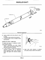
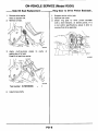
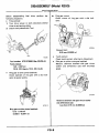
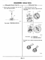
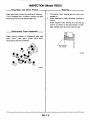
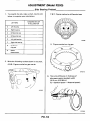
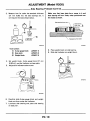
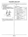
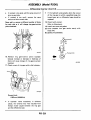
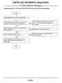
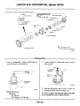
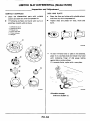
PROPELLER SHAFT &
DIFFERENTIAL CARRIE1
SECTION
PD
CONTENTS
......................................................
FINAL DRIVE (Model R200) ...............................................
ON-VEHICLE SERVICE (Model R200) ........................................
REMOVAL AND INSTALLATION (Model R200) ...............................
DISASSEMBLY (Model R200) . . . . . . . . . . . . . . . . . . . . . . . . . . . . . . . . . . . . . . . . . . . . . . .
INSPECTION (ModelR200) . . . . . . . . . . . . . . . . . . . . . . . . . . . . . . . . . . . . . . . . . . . . . . . . .
ADJUSTMENT (Model R200) ...............................................
ASSEMBLY (Model R200) ..................................................
LIMITED SLIP DIFFERENTIAL (Model R200) ................................
SERVICE DATA AND SPECIFICATIONS (S.D.S.)..............................
SPECIAL SERVICE TOOLS ................................................
PROPELLER SHAFT
PD- 2
PD- 4
PD- 5
PD- 7
PD- 8
PD-13
~ ~ - 1 4
PD-24
PD-30
PD-38
PD-41
PROPELLER SHAFT
Companion flange
'
T
,* n .a E
39-44N'
Propeller shaft
,- Sleeve yoke
PO427
General
0
Inspect propeller shaft tube surface for dents
or cracks.
If damaged, replace propeller shaft assembly.
If center bearing is noisy or damaged, replace
center bearing.
PROPELLER SHAFT VIBRATION
To check and correct an unbalanced propeller
shaft, proceed as follows:
1. Remove undercoating and other foreign
material which could upset shaft balance, and
check shaft vibration b y road test.
2. If shaft vibration is noted during road test,
disconnect propeller shaft a t differential
carrier companion flange, rotate companion
flange 180 degrees and reconnect propeller
shaft.
3. Again check shaft vibration.
PD-2
If vibration
still persists, replace propeller shaft assembly.
PROPELLER SHAFT
-Removal and Installation
0
Inspection
Put match marks on flanges and separate
propeller shaft from differential carrier.
Inspect propeller shaft runout. If runout
exceeds specifications, replace propeller shaft
assembly.
SPDlO6
SPD103
0
Draw out propeller shaft from transmission
and plug up rear end of transmission rear
extension housing.
Runout limit: 0.6 mm (0.024 in)
Inspect journal axial play.
If the play exceeds specifications, replace
propeller shaft assembly.
Journal axial play:
0 mm (0 in)
Transmission
7
SPD359
PD-3
~
FINAL DRIVE (Model R200)
PD-4
ON-VEHICLE SERVICE (Model R200)
Front Oil Seal Replacement
1. Remove propeller shaft.
2. Loosen drive pinion nut.
,Tool
Tool number: ST31520000 (
5. Apply multi-purpose grease to cavity at sealing
lips of oil seal.
Press front oil seal into carrier.
\
-
)
SPD520
Tool number: KV38100500 (
3. Remove companion flange.
-.
6. Install companion flange and drive pinion nut.
7 . Install propeller shaft.
4. Remove front oil seal.
SPD519
Tool number: ST33290001 (525810-A)
PD-5
ON-VEHICLE SERVICE (Model R200)
- Ring Gear t o Drive Pinion Backlash-
-Side Oil Seal Replacement
1. Support carrier with a jack.
2. Remove rear cover.
3. Check ring gear to drive pinion backlash
with a dial indicator, a t several points. I f it
is not within specifications, adjust it after removing final drive assembly.
1. Remove drive shafts.
Refer t o section RA.
2. Remove oil seal.
-.
.
SPD521
3. Apply multi-purpose grease to cavity a t
sealing lips of oil seal.
Press-fit oil seal into carrier.
.
Toolnumber: KV38100200(
SPD522
-
4. Install drive shafts.
PD-6
SPD523
REMOVAL AND INSTALLATION (Model R200)
Removal
Installation
Remove propeller shaft.
Refer t o Propeller Shaft.
Remove drive shafts.
Refer t o RA section.
Pull off differential carrier backward together with jack.
Full final drive with recommended gear oil.
Refer t o section GI.
1
Filler opening
SPD348
SPD5ll
CAUTION:
Be careful not t o damage spline and sleeve
yoke when removing propeller shaft.
After carrier assembly is removed, support
suspension member on a stand t o prevent i t s
insulators being twisted or damaged.
PD-7
DISASSEMBLY (Model R200)
Pre-in: xtion
Ring gear runout
Check runout of ring gear with a dial indicator.
Before disassembling final drive, perform the
following inspection.
a Total preload
1) Turn drive pinion in both directions several
times t o set bearing rollers.
21 Check total preload with Tool.
Runout limit:
0.05 mm (0.0020 in)
Tool
a
PD245
Tool number: ST3127SOOO (SeeJ25765-A.)
Total preload:
1.23 - 2.30 N m
(12.5 - 23.5 kg-cm, 10.9 - 20.4 in-lb)
a
a
Tooth contact
Check tooth contact, referring t o Adjustment.
Side gear t o pinion mate gear backlash
Measure clearance between side gear thrust
washer and differential case with thickness
gauge.
Ring gear t o drive pinion backlash.
Check backlash of ring gear with a dial indicator at several points.
SPD370
SPDSl3
Ring gear-to-drive pinion backlash:
0.13 - 0.18 mm
(0.0051 0.0071 in)
-
PD-8
Clearance between side gear thrust washer
and differential case:
Less than 0.15 mm (0.0059 in)
DISASSEMBLY (Model R200)
Differential Carrier
1. Using three spacers [45 mm (1.77 in)], mount
carrier on Tool.
3. Remove side bearing caps.
PD343
Spacer
LTool
SPD525
Tool number: KV38100800 (J25604-1)
4. Using Tool, lift differential case assembly
out.
2. Put match marks on one side of side bearing
cap and gear carrier with paint or punch t o ensure that it is replaced in proper position
during reassembly.
Bearing caps are line-board during manufacture and
should be put back in their original places.
PD344
Tool number: HT72400000 (
-
)
Be careful t o keep the side bearing outer races
together with inner race - do not mix them up.
5PD526
PD-9
DISASSEMBLY (Model R200)
Differential Carrier (Cont'd)
5. Loosen drive pinion nut and pull off companion flange.
7. Remove oil seal.
8. Remove pilot bearing together with pilot
bearing spacer and front bearing inner race
with Tool.
4
Tool
PD345
Tool number: ST31520000 (
-
1
PD346
PD348
6. Take out drive pinion together with rear
bearing inner race, bearing spacer and adjusting washer.
Tool number: KV38100401 (
-
)
9. Remove side oil seal.
10. Remove pinion bearing outer races with a brass
drift.
PD349
PD-10
DISASSEMBLY (Model R200)
-Differential
Carrier (Cont'd)
-
11. Remove pinion rear bearing inner race and
pinion height adjusting washer.
Differential Case
1. Remove side bearing inner races.
To prevent damage to bearing, engage puller paws
with grooves.
'7
I
Ir
@
Groove
PD179
Tool number: ST30031000 (52291241)
Tool
@?<
SPD529
Tool number: @ ST33051001 (
@ ST33061000 (581072)
Be careful not to confuse the right and left hand
parts.
SPD022
PD-11
DISASSEMBLY (Model R200)
-Differential
Case (Cont'd)
2. Loosen ring gear bolts in a criss-cross fashion.
3. Tap ring gear off the gear case with a soft
hammer.
Tap evenly all around to keep ring gear from
binding.
SPD024
4. Punch off pinion mate shaft lock pin from ring
gear side.
Lock pin is calked at pin hole mouth on differential case.
SPD025
PD-12
INSPECTION (Model R200)
-Ring Gear and Drive Pinion
Bearing
Check gear teeth for scoring, cracking or chipping.
If any damaged part is evident, replace ring gear
and drive pinion as a set (hypoid gear set).
1. Thoroughly clean bearing and dry with compressed air.
2. Check bearings for wear, scratches, pitching or
flaking.
Check tapered roller bearing for a burned out
portion as shown in the figure below. I f damaged, replace outer and inner races as a set.
-Differential Case AssemblyCheck mating surfaces of differential case, side
gears, pinion mate gears, pinion mate shaft,
thrust block and thrust washers.
tube checked
I
SPD458
SPD584
PD-13
ADJUSTMENT (Model R200)
To avoid any confusion while calculating bearing
shims, it is absolutely necessary t o stay with the
metric system. I f you measure anything in inches,
the results MUST be converted t o the metric
system. You can use a conversion chart or a
calculator as illustrated.
2. Slide pinion rear bearing inner race, bearing
preload adapter and pinion bearing adjusting
spacer over hex head long bolt.
Pinion rear bearinoinner race
Taai
7
Pinion
bearing
adjusting
sixcer
SPD533
Tool number:
Bearing preload adapter
SPD531
(525269-26)
3. Install these parts into gear carrier.
4. Stand front bearing pilot support on the
bench with the appropriate side up and as-
Setting Up Each Tool
Set up each tool, rear pinion bearing and front
pinion bearing before adjusting pinion height
and drive pinion bearing preload.
1. Install rear pinion bearing pilot into gauge
plate and slide over hex head long bolt.
semble front pinion bearing pilot, front pinion
bearing inner race and lead preload washer.
Ensure that all parts are seated.
4mb-
Pinion front bearing inner race
SPD534
SPD532
Tool number:
@ Hex head long bolt (J25269-23)
@ Gauge plate
(525269-11
@ Rear pinion bearing pilot (525269-2)
PD-14
Tool number:
@ Lead preload washer
(525269-25)
@ Front pinion bearing pilot
(525269-3)
@ Front bearing pilot support
(525269-29)
ADJUSTMENT (Model R200)
-Setting
Up Each Tool (Cont'd)
-
5. Holding these parts together, slide the assembly over hex head long bolt into gear
carrier. Install support nut. Finger-tighten
the nut and ensure that all parts turn freely
and are properly aligned.
Drive Pinion Height
1. Install two side bearing discs with arbor
assembly. Ensure that arbor turns freely.
@?
SPD537
Tool number:
@ Arbor assembly
@ Side bearing disc
SPD535
(J23597-1)
(J25269-4)
6. Tighten support nut carefully t o correct preload of 0.6 to 1.0 N m (6t o 10 kg-cm, 5.2 to
2. Place side bearing discs with arbor assembly
into differential carrier.
8.7 in-lb).
Lift spring loaded plunger and place it on the
face of gauge plate.
SPD536
Tool number: (J25765-A)
SPD538
PD-15
ADJUSTMENT (Model R200)
Drive Pinion Height (Cont'd)
3. Install bearing caps.
4. Install dial indicator and tighten hold down
clamp.
6. Rotate gauge plate until the plunger falls off
gauge plate and read dial indicator (Read the
dial indicator diectly).
Repeat to ensure accuracy.
Springloaded
plunger.
extended
SPD539
Tool number:
@ Hold down clamp
@ Dial indicator clamp
@ Dial indicator
(58001-1)
(58001-2)
(J8001-6)
SPD541
7. Read head number (H) on drive pinion head.
The figure for H i s a dimensional variation in units
of 0.01 mm (0.0004 in) against a standard
measurement.
5. To zero dial indicator, rotate arbor and plunger
back and forth and note highest deflection (the
point where needle changes direction). Set dial
indicator a t zero.
L Head number ( H )
SPD542
PD-16
ADJUSTMENT (Model R200)
-Drive
I
2.
1. To determine pinion bearing preload, disassemble pinion heighdbearing preload tools
and measure thickness of lead washer. This is
the correct size pinion bearing adjusting washer
required.
OPERATION
LINE #
1.
Drive Pinion Preload
Pinion Height (Cont'd)-
3.00mm
Standard number
I Dial indicator reading (Step 61
3.
A 0 0 lines 1 and 2
4.
"H"factor (from drive pinion1 (Step 71
5.
"H" factor sign 0
I
I
If a lead washer i s not available, use a piece of
thick roll solder t o obtain preload washer size.
line 5: SUBTRACT line 4
PLUS SIGN
from 3. Enter difference on line 6
MINUS SIGN
and 4. Enter sum
6.
line 5: A 0 0 liner 3
on line 6
Warher size
Example: Dial Indicator Reading: 0.3 mm
SPD543
Number on Pinion Head: +2
2. Select the proper washer (Refer t o S.D.S.).
3.00 (standard measure)
+0.3
-(indicator reading)
3.3 (Pinion head is plus, so you
-0.02
-SUBTRACT it)
3.28 (mm = total pinion washer you
will need)
9. Select the proper washer (Refer t o S.D.S.).
If you cannot find the desired thickness of washer,
use washer so that thickness i s the closest t o the
kalculated value.
Example:
3.28 mm (Calculated total pinion washer
i n step 8)
The correct washer is 3.27 mm
(Part number 38154 P6023).
PD-17
If you cannot find shims with the desired
thickness, use shims so that the total thickness
is the closest t o the calculated value.
Sometimes the correct dimension cannot be set
with washers alone. In these cases, washers may
be used in combination with drive pinion
bearing adjusting spacers. (Refer t o S.D.S.)
ADJUSTMENT (Model R200)
Side Bear 3 Preload
C & D: Figures marked on differential case
1. To simplify the job, make a chart, like the one
below, t o organize your calculations.
~~
-
~
HUNDREDTHS OF
A MILLIMETER
LETTERS
A
. Left housing
B
-
Right housing
C . Differential case
I
D . Differential case
I
-1
E . Left side bearing
PD359
H: Figures marked on ring gear
ring gear
I
G - Spacer
measurement
I
2. Write the following numbers down in the chart.
A & 6: Figures marked on gear carrier
G: This is the difference in thickness of
side spacer against standard width
i8.10mm (0.3189i n ) ]
(G = Standard spacer - Measured spacer).
PD358
PD-18
ADJUSTMENT (Model R200)
Side Bearing Preload (Cont'd)
3. Measure how far under the standard thickness
[21 mm (0.83 in)] the side bearings are. It
will require the toolsshown below.
Make sure that base plate has a recess in it and
that bearing will turn freely when positioned over
the recess as shown.
Side bearing inner race
Side bearing
youterrace
4
measurement
'LRecessed surface plate
SPD547
SPD545
Tool number:
@ 4-step gauge block
@ Baseplate
@ Weight block
8. Place weight block on side bearing.
9. Slide dial indicator on weight block.
(525407-1)
(525407-2)
(525407-3)
4. Set weight block, 4-step gauge block [21 rnm
(0.83 in)] and dial indicator on base plate.
5. Adjust dial indicator scale t o zero.
SPD548
SPD546
6. Carefully slide 4-step gauge block and weight
block out from under dial indicator.
7. Lubricate side bearing and place side bearing
on base plat-.
PD-19
ADJUSTMENT (Model R200)
Side Bearing
10. Turn weight block a few times t o ensure that
bearing is properly seated.
11. Read dial indicator.
Normal indication:
0.10 0.30mm (0.0039 0.0118 in)
If the needle fluctuates erratically, then bearing
is either dirty or defective and should be
cleaned or replaced.
-
-
I
eload (Cont'd)
13. Calculate washer thickness following the charts
below.
Left (ring gear) side:
.INE #
I
1L
I
OPERATION
Left ride standard number
-=
2L
Enter "A" factor (gear carrier)
3L
Enter "0" factor (differential case1
4L
Enter "E"factar
5L
ADD Lines 1 L, ZL. 3L. and 4L. Enter SUM
6L
Enter "C" factor (differential carel
7L
8L
9L
I
1
(left bearing1
SUBTRACT Line 6L from 5 L - Enter
DIFFERENCE
I Enter "H'factor king gear1
I Enter "H"factor'r sign 0
I
I
I
PLUS SIGN + Line 9L;SUBTRACT
Line 8 L from 7L.
SPD549
12. Measure both bearings in the same way and
write the left side bearing measurement next
t o "E" and the right side bearing measurement
next t o "F".
and 8L. Enter rum on Line 1OL.
1OL
PD-20
I
Left side shim size "TI"
I
ADJUSTMENT (Model R200)
Side Bearing Preload (Cont'd)
I-1R 1 Right side standard number
ZR
Enter "8" factor lgear carrier)
3R
Enter "F" factor (right bearing)
4R
Enter "G" factor I R 200 only)
(See Chart Below1
11.95mm
I
Example:
6R
Enter "0" factor (differential case)
7R
SUBTRACT Line 6R from 5 R .
Enter DIFFERENCE
8R
Enter "H" factor Iring gear)
9R
Enter "H" factor's sign 0
H
1-
Right side shim size "T,"
A.
Side bearing spacer -Standard size
C.
SUBTRACT Line 8 from Line A and enter
DIFFERENCE on Line 4R of right side of
chart.
2
I -
+
shim
2.05
MINUS SIGN - Line 9R; SUBTRACT
Line 8R from 7R.
Enter difference on line 10R.
G FACTOR CALCULATION R200 ONLY
Right Side T2
+,-++-1 1
1
-
PLUS SIGN + Line 9R: ADD Liner 7R
and 8R. Enter sum on Line 10R.
I
l -
+
ADD Lines 1R. ZR.3R.and4R.
Enter SUM
I
l
Left Side T1
5R
10R
The formulas are as follows:
TI = A - C + D + E - H + 2.05 (mm)
T, = B - D + F + G + H + 1.95 (mm)
I
I
8.10 m m
2.31
2.19
-5
I
3
5
- 1
2.14
The measurement for the shim pack on the left
(T1) should be 2.28 mm and for the right (T2)
2.14 mm. To check the accuracy of your work in
the previous step, the side bearing shim measurement should be figured with a Side Bearing Shim
Calculator.
PD-21
ADJUSTMENT (Model R200)
Side Bearing Preload (Cont’d)
Follow the instructions for the sample given below:
EXAMPLE CALCULATOR
Left Side
Step 1. Move slide 1 t o place C 3 in line with an
arrow.
Step 2. Move slide 2 t o place D 3 in line with
c 3.
Step 3. Move slide 3 t o place E 18 in line with H
-2.
Step4. Read answer a t left side arrow, 2.28mm
or close t o .OB7 in.
SPD550
Right Side
Step 1. Move slide 1 to place B
arrow.
3 in line with an
Step 2. Move slide 2 t o place G 7 in line with
D 3.
Step 3. Move slide 3 to place F 14 in line with
H 2 (red scale for right side).
Step 4.
Read answer a t right side arrow 2.14mm
or closer t o ,086 in.
14. Compare these answers with the answers on
the previous page. If both answers agree, proceed t o the next step.
15. Select the proper washer (Refer t o S.D.S.).
If you cannot find the desired thickness of washer,
use washer so that thickness i s the closest t o the
calculated value.
PD-22
J
SPD551
ADJUSTMENT (Model R200)
Tooth Contact
Gear tooth contact pattern check is necessary t o
verify correct relationship between ring gear and
drive pinion.
Hypoid gear set which are not positioned properly
may be noisy, or have short life or both. With a
pattern check, the most desirable contact for low
noise level and long life can be assured.
3. Hold companion flange steady by hand and
rotate the ring gear in both directions.
1. Thoroughly clean ring gear and drive pinion
teeth.
2. Sparingly apply a mixture of powdered ferric
oxide and oil or equivalent t o 3 or 4 teeth of
ring gear drive side.
SPD308
\
H r l conQct
\
SPD357
Usually the pattern will be correct if you have
calculated the shims correctly and the backlash
is correct.
However, in extremely rare cases you will have t o
use trial-anderror processes until you get a good
tooth contact pattern.
The tooth pattern i s the best indication of how
well a differential has been set up.
Fam contact
Tom contact
To correct. increase thickness of Pinion
height adiurting washer in order to bring
drive pinion close to ring gear.
Flank contact
To correct, reduce thickness of pinion
height adjusting washer in order to make
drive pinion go away from ring gear.
*
J%
Correct tooth ontact
1
PD-23
SPD007
ASSEMBLY (Model R200)
Differei
31
1. Install side gears, pinion mate gears, thrust
washers and thrust block into differential
case.
Case
Clearance between side gear thrust washer and
differential case:
0.10 0.20 mm (0.0039 0.0079 in)
-
-
4. Install pinion mate shaft lock pin with a punch.
punch.
Make sure lock pin is flush with case.
SPD552
2. Fit pinion mate shaft t o differential case
so that it meets lock pin holes.
SPD030
5. Apply gear oil t o gear tooth surfaces and thrust
surfaces and check t o see they turn properly.
.Gear oil
SP0553
3. Adjust clearance between rear face of side
gear and thrust washer by selecting side gear
thrust washer (Refer t o S.D.S.).
u
SPD322
SPD029
PD-24
ASSEMBLY (Model R200)
Differential Case (Cont'd)
Differential Carrier
6. Apply locking agent [Locktite (stud lock) or
equivalent] to contacting surfaces of ring gear
and differential case, then place differential
case on ring gear.
1. Press-fit front and rear bearing outer races
with Tools.
Pinion front bearing
outer race
7
SPDSOO
7. Apply locking agent [Locktite (stud lock) or
equivalent] t o ring gear bolts, and install them.
Tighten bolts in a crisscross fashion, lightly tap
ping bolt head with a hammer.
8. Press fit side bearing inner races on differential
case with Tool.
SPD555
Tool number:
8 ST30611000 (J25742-1)
@ ST30621000(
)
@ ST30613000 (525742-3)
-
PD353
Tool number:
@ KV38100300 (525523)
@ ST33061000 (58107-2)
PD-25
ASSEMBLY (Model R200)
Differential Carrier (Cont’d)
2. Select pinion height adjusting washer and
pinion bearing adjusting washer spacer, referring t o Adjustment.
3. Install pinion height adjusting washer in drive
pinion, and press fit rear bearing inner race in
it with press and Tool.
5. Apply multi-purpose grease to cavity at sealing
lips of oil seal.
Install front oil seal.
SPO557
Tool number: KV38100500 (
SPD377
Toolnumber: ST30901000(
-
-
1
6. Install companion flange, and tighten pinion
nut t o specified torque.
)
4. Set drive pinion assembly (as shown in figure
below) in differential carrier and install drive
pinion with press and suitable tool.
Ascertain that threaded portion of drive pinion and
pinion nut are free from oil or grease.
Stop when drive pinion touches bearing.
PD466
Suitable spacer
Toolnumber: ST31520000(
Pinion bearing adjusting space
Pinion bearing adjusting washer
Pinion front bearing inner race
ront pilot bearing spacer
Front pilot bearing
SPD556
PD-26
-
ASSEMBLY (Model R200)
Differential C
7. Turn drive pinion in both directions several
ier (Cont'd)
10. Insert left and right side bearing adjusting
washers in place between side bearings and
carrier.
times, and measure pinion bearing preload.
PD340
SPD558
Tool number:
ST3127SOOO (See525765-A.)
11. Drive in side bearing spacer with Tool.
Pinion bearing preload (With front oil seal):
1.13 1.72 N m
(11.5 17.5 kgcm, 10.0 15.2 in-lb)
-
-
-
When pinion bearing preload is outside the
specifications, replace pinion bearing adjusting
washer and spacer with a different thickness.
8. Select side bearing adjusting washer.
Refer to Adjustment.
9. Install differential case assembly with side
bearing outer races into gear carrier.
SPD559
Tool number: KV38100600 (525267)
PD-27
ASSEMBLY (Model R200)
Differential C
12. Align mark on bearing cap with that on gear
carrier and install bearing cap on gear carrier.
.rier (Cont'd)
14. Measure ring gear-todrive Dinion backlash
with a dial indicator.
I
SPD526
I.
SPD513
Ring gear-to-drive pinion backlash:
0.13 0.18 mm
(0.0051 - 0.0071 in)
13. Apply multi-purpose grease to cavity a t sealing
lips of oil seal.
Install side oil seal.
-
If backlash is too small, decrease thickness of
right shim and increase thickness of l e f t shim
by the same amount.
If backlash is too great, reverse the above procedure.
Never change the total amount of shims as it will
change the bearing preload.
15. Check total preload with Tool.
When checking preload, turn drive pinion in both
directions several times t o set bearing rollers.
L Tool
SPD56O
/
.
.
PD340
Tool number: ST3127SOOO (See 525765-A.)
Total preload:
1.23 - 2.30 N m
(12.5 23.5 kg-cm, 10.9 20.4 in-lb)
-
PD-28
-
ASSEMBLY (Model R200)
Differential C
0
0
If preload is too great, add the same amount of
shim t o each side.
I f preload is too small, remove the same
amount of shim t o each side.
Never add or remove a different number of shims
for each side as it will change ring gear-to-drive
pinion backlash.
,rier (Cont'd)
0
18. Check tooth contact.
Refer t o Adjustment.
19. Install rear cover and gasket.
20. Drive breather into gear carrier evenly with
brass drift.
Be careful of i t s direction.
SPD561
16. Recheck ring gear-todrive pinion backlash
because increase or decrease in thickness of
shims will cause change of ring gear-to-pinion
backlash.
17. Check runout of ring gear with a dial indicator.
SPD524
Runout limit:
0.05 mm (0.0020 in)
0
I f the backlash varies greatly when the runout
of the ring gear is within a specified range, the
hypoid gear set or differential case should be
replaced.
If backlash varies excessively i n different
places, the variance may have resulted from
foreign matter caught between the ring gear
and the differential case.
PD-29
+
Front
SPD825
LIMITED SLIP DIFFERENTIAL (Model R200)
Trouble-shooting and diagnoses
Customer complaint: Final drive has high-pitched chattering noise during turning maneuvers.
Start
1
1
Change differential gear oil to the recommended oil.
I s chattering noise still ev
tight circles 5 clockwise a r d 5 counterclockwise?
I Yes
Check if differential torque is within specified range.
Refer to CHECK
0.
.
Explain that slight chattering noise may occur for
approx. 100 km (62miles) after changing oil. It is
not a problem.
Disassemble final drive and check parts.
O.K.
Perform road test and check noise level.
Disassemble final drive and replace limited slip
differential assembly.
O.K.
Explain that slight chattering noise may occur for
approx. 100 km (62 miles) after changing oil. It is
not a problem.
PD-30
1
LIMITED SLIP DIFFERENTIAL (Model R200)
Trouble-shooting and diagnoses (Cont'd)
Customer complaint: Rear wheels slip and remain stuck in mud or on snowy roads.
Start
1
Check if vehicle has limited s
Refer to CHECK @.
Explain that vehicle does not have limited slip
Yes
Explain that purpose of limited slip
differential is to improve cornering performance but
rear wheels may slip or get stuck in mud or on snowy
Check ifdifferential torque i s within specified range.
Refer to CHECK
8.
Disassemble final drive and check parts.
Disassemble final drive and replace limited slip
differential assembly.
approx. 100 km (62 miles) after changing oil.
It is not a problem.
PD-31
LIMITED SLIP DIFFERENTIAL (Model R200)
Trouble-shooting and
CHECK @
:I
Check differential torque.
1. Drive vehicle enough to warm up differential
oil.
2. Lift both rear wheels off ground.
3. Shift transmission gear into 1st (M/T model) or
P range (A/T model).
4. Release parking brake.
5. Check differential torque a t wheel stud bolt.
1100) 137
1141
118
(801 '(12)
98
a%
3
(10)
F
$ (601- 78
m
18)
c
B
59
(40). (61
39
(41
(201.
20
Differential torque (on vehicle):
New parts:
49 - 118 N m
(5 - 12 kg-m, 36 - 87 ft-lb)
Used parts:
29 - 88 N m
(3 - 9 kg-m, 22 - 65 ft-lb)
m
3
I I_
t
L
A
I
57.15 mrn 12.2500 in1
SPD820
L: Length of torque wrench
SPD823
CHECK @ : Limited slip differential
identification.
1. Lift both rear wheels off ground.
2. Turn one rear wheel by hand.
3. If both rear wheels turn in the same direction
simultaneously, vehicle is equipped with
limited slip differential.
PD-32
LIMITED SLIP DIFFERENTIAL (Model R200)
~~~~~~~~~
Pay attention t o direction of partrand assembly procedures.
Oifferemial care muple screw
,Spacer
-
(0.8 1.1.5.8 -8.0)
Friction disc
‘-Differential
[91 :
N m (kgm, ft-lb)
*: Pay attention to its direction.
case A
SPD813
1. Prior t o disassembly, measure differential torque and record it as a reference.
2. Loosen screws on differential cases A and B
using a press.
ST33061000
KV381051SO
1x34292)
$\
16-
SPD507
Vise
Differential torque:
New parts
25 - 49 N m
(2.5 - 5 kgm, 18 - 36 ft-lb)
3. Separate differential case A and B. Draw out
SPD62O
component parts (discs and plates, etc.).
Put marks on gears and pressure rings so that they
can be reinstalled in their original positions.
PD-33
LIMITED SLIP DIFFERENTIAL (Model R200)
Inspection ar
DISC AND PLATE
CONTACT SURFACES
0
Adjustment
Clean the disassembled parts with suitable
solvent and blow dry with compressed air.
If following surfaces are found with burrs or
scratches, smooth with oil stone.
0
Clean the discs and plates with suitable solvent
and blow dry with compressed air.
Inspect discs and plates for wear, nicks and
burrs.
1 Differential case A
2 Differential care B
3 Pressure ring
4 Pinion mate shaft
5 Pinion mate gear
6 Sidegmr
SPD478
0
To test if friction disc or plate is not distored,
place it on a surface plate and rotate it by hand
with indicating finger of dial gauge resting
against disc or plate surface.
If it exceeds limits, replce with a new plate.
SPD621
Allowable warpage:
0.08 mm (0.0031 in)
PD-34
LIMITED SLIP DIFFERENTIAL (Model R200)
inspection and P
In order t o determine if the wear limit has been
exceeded for each friction disc, friction plate
and spring plate, subtract the thickness of projected portions from the thickness of frictional
surface. If wear of any of the part exceeds the
limit, replace with a new one. (For friction
plate, choose new one whose thickness is
closest to old one's thickest figure.)
lstment (Cont'd)
CLUTCH PLATES END PLAY
1. Determine dimension "A"
equation.
with following
A=C- D + E
B
: Measuring points
A : Projected portion
B : Frictional surface
A - B =Wear limit
Wear limit:
0.1 mm (0.004 in)
SPD817
SPD403
2. Measure distance "F".
/------
PD-35
LIMITED SLIP DIFFERENTIAL (Model R200)
Inspection and Adjustment
(Cont'd)
-
Assembly
a
3. Measure thickness of each side of spring plates.
(L, : Right side, L,: Left side)
As an aid to installation, apply sufficient
amounts of recommended L.S.D. gear oil
(Refer to MA section) to the faces of pressure
rings, discs and plates to be assembled together.
SPD479
SPD814
a
4. Measure thickness of each side of friction
plates, friction disc and spacer.
(K, : Right side, K, : Left side)
5. Determine dimension "M"
equations.
Install spring plates, friction plates and friction
discs.
Pay particular attention to the direction of clutch
plates and their assembly sequence.
with following
Friction plate
A
Spring plate
M = L, + Lz + K, + K,
6. Determine end play "P" with following equation.
P=A-F-M
End play:
0.05 - 0.20 mm (0.0020 - 0.0079 in)
7. If not within specification, select discs and
plates to adjust correctly.
EY
u
spacer
SPD623
PD-36
LIMITED SLIP DIFFERENTIAL (Model R200)
ICont'd)
Always attach pinion mate shaft t o "V" groove
in pressure ring with flat surfaces facing up and
down.
After assembly, measure differential torque. If
it is not within the specification, adjust it by
selecting friction disc (Refer t o S.D.S.).
KV381051SO
(X342921
~ r e r r u r ering . \
SPD483
Install differential case A on differential case B.
Align cases by their match marks, then install
screws while pushing differential case down
with a press.
SPD507
PD-37
SPDSZO
Differential torque:
New parts
25 - 49 N m
(2.5 - 5 kg-rn, 18 - 36 ft-lb)
SERVICE DATA AND SPECIFICATIONS (S.D.S.)
Propeller Shaft
GENERAL SPEC1FlCATlONS
Unit mm Inn1
I
I
2 seater
VG30E turbo
VG30E without turbo
Applied model
M/T
A/T
M/T
2+2 seater
VG30E without t u r h
A/T
M/T
VG30E turbo
A/T
A/T
2S71A
Propeller shaft model
I
Coupling method with franimiirion I
Distance between yokes
I
2
Number of joints
Sleeve type
71 (2.801
Shell type Inon-disassembly type)
Type of journal bearing
665 126.18) 685 (26.971 665 (26.181 685 126.91 1 865 134.061 885 (34.84)
Shaft length [Spider to spider)
I
Shaft outer diameter
885 134841
75 12.95)
SERVICE DATA
Unit: mm l i n l
Model
2S71A
0.6 (0.0241
Propeller shaft runout limit
TIGHTENING TORQUE
Unit
Nm
kg-m
ft-lb
Shaft to companion
flange bolts
39-44
4.0-4.5
29-33
0 (01
Journal axial play
Differenl 1 Carrier
SERVICE DATA
GENERAL SPECIFICATIONS
VG30E
without turbo
Applied model
mm (in)
Gear ratio
Number of teeth
(Ring gear/Drive pinion1
Oil capacity (approx.)
P IUS pt, Imp pt)
I
I
3.700
37/10
1
I
WOO
Drive pinion preload
[With front oil seal1
N m (kg-cm, in-lb)
200 17.871
I
Final drive model
Drive pinion bearing preload
adiustina method
WOO
Final drive model
Ring gear pitch
diameter
VG30E turbo
Adjusting spacer and washer
1.13 - 1.72
111.5-17.5, 10.0- 15.21
3.545
39/11
1.E 13-7/8.3-1/81
Drive pinion preload
(Without front oil reall
N m Ikgcm. in-lb)
Total preload
-
1.0. 1.3 110 13,8.7
-
'
N m Ikgcm, in-lbl
1.23 2.30
112.5.23.5. 10.9 - 20.41
Side bearing adjusting method
Backlash
Drive pinion t o ring gear
mm (in1
Side gear t o pinion mate gear
(Clearance between ride gear
t o differential case1 mm (in)
Ring gear runout limit mm (in1
PD-38
- 11.31
Shim
0.13 .0.18 (0.0051 .0.0071
-
I
0.10 0.20 (0.0039~0.00191
0.05 (0.00201
SERVICE DATA AND SPECIFICATIONS (S.D.S.)
Differential Carrier (Cont’d)
Pinion height adjusting washer
Thickness mm (in1
3.09
3.12
3.15
3.18
3.21
3.24
3.27
3.30
3.33
3.36
3.39
3.42
3.45
3.48
3.51
3.54
3.57
3.60
3.63
3.68
0.05
0.07
(0.12171
(0.1228)
(0.1240)
(0.1252)
(0.12641
(0.12761
(0.1287)
(0.12991
(0.13111
10.13231
(0.13351
10.1346)
10.13581
10.1370)
10.1382)
10.13941
(0.14061
(0.14171
(0.1429)
10.1441)
10.0020)
10.0028)
Side bearing adjusting washer
Thickness mm lid
Part No.
38154.P6017
38154-P6018
38154-P6019
38154-P6020
38154-P6021
38154-P6022
38154P6023
381 54P6024
38154P6025
381WP6026
38154P6027
38154-P6028
381 54P6029
381 54-P6030
38154.P6031
38154-P6032
38154.P6033
38154-P6034
38154-P6035
38154-P6036
3845328600
38454-28500
2.00
2.05
2.10
2.15
2.20
2.25
2.30
2.35
2.40
2.45
2.60
2.55
2.60
Part No.
(0.07871
10.08071
(0.08271
(0.08461
10.08661
10.0886)
10.0906)
10.0925)
10.09451
10.09651
10.0984)
(0.10041
(0.10241
38453-N3100
38453-N3101
38453-N3102
38453-N3 103
38453-N3104
38453-N3105
38453-N3106
38453.N3107
38453.N3108
38453-N3 109
38453-N3110
38453-N3111
38453-N3112
Side gear thrust washer
Thickness mm (in)
Part No.
0.75.0.80 (0.0295 - 0.03151
0.80.0.85 10.0315 - 0.0335)
0.85.0.90 10.0335 - 0.0354)
0.90- 0.95 10.0354.0.0374)
38424N3100
38424.N3101
38424.N3102
38424-N3103
TIGHTENING TORQUE
Drive pinion bearing preload adjusting washer
~~~
Thickness mm (in)
Part No.
3.80-3.82 10.1496-0.15041
3.82-3.8410.1504-0.15121
3.84-3.86 10.1512-0.15201
3.86-3.88 (0.1520-0.15281
3.88 - 3.90 10.1528 0.15351
3.90.3.92 10.1535 0.15431
3.92.3.94 (0.1543 0.15511
3.94-3.96 10.1551 -0.15591
3.96.3.98 10.1559.0.1567)
3.98.4.00 10.1567.0.1575)
4.00 4.02 10.1575. 0.15831
4.02-4.04 10.1583-0.1591)
4.04-4.06 (0.1591 -0.1598)
4.06 4.08 (0.1 598 - 0.1606)
4.08-4.10 (0.1606-0.16141
3812561001
3812661001
3812761001
3812861001
3812961001
3813061001
38131-61001
3813261001
3813361001
3813461001
3813561001
381366100 1
3813761001
38138-61001
3813961001
-
-
R200
Type
Unit
Nm
Final drive installation
Drive shaft to rear axle
VG30E without
turbo
VG30E turbo
39.49
4-5
29.36
59-69
6-7
43.51
88-118
90.120
65-87
Mounting insulator
to body
8011
Nut
29-39
59-78
3-4
6-8
22.29
43.58
Dkfferentia carrier to
59. 78
6-8
43.58
Rear cover to
mounting insulator
~u~pension
member
Drive pinion bearing preload adjusting spacer
55.10 12.16931
55.40 (2.1811)
55.70 12.1929)
56.00 (2.20471
56.25 12.2146)
ft-lb
~~~
Final drive assembly
Drive pinion nut
Length mm (in1
kg-m
Part No
3816564002
38165-64003
38165-64004
3816561001
3816661001
PD-39
186-294
19-30
137-217
Ring gear bolt [using
Locktite (stud lock1 or
equivalent]
132. 152
13.5. 15.5
98. 112
Side bearing cep bolt
88 98
9.0 - 10.0
65.72
-
- 2.4
-
Rear cover fixing bolt
16 - 24
1.6
Companion flange to
prapeller shaft fixing
bolt
39 .44
4.0 4.5
29 .33
Filler and drain plug
59.98
6.10
43-72
12. 17
SERVICE DATA AND SPECIFICATIONS (S.D.S.)
Final Drive
SERVICE DATA
N m (kg-m. ft-lbl
49.118 (5.12.36 -87)
New parts
Differential torque
New Darts
N m Ikg-m. ft-lbl
1
25 - 49 (2.5.5. 18.361
Wear limit of friction disc. friction
mm (in)
plate and wring plate
Allowable warpage o f friction disc
mm (in)
and friction plate
End play
mm (in)
0.1 (0.0WI
I
I
0.08 l0.0031)
0.05.0.20
~0.0020~0.0079l
Friction plate
1
Thickness mrn (in)
I
1.75 (0.0689)
1.85 10.0728)
Part number
38432-N9000
38432-N9001
Thickness mm (in)
Part number
1.75 10.0689)
38433.N9000
TIGHTENING TORQUE
Unit
N.m
kg-m
ft-lb
Differential case couple
screw
8-11
0.8-1.1
5.8-8.0
PD-40
SPECIAL SERVICE TOOLS
~
Tool number
(Kent-Moore No.)
Tool name
ST31520000
(
-
)
Drive pinion flange wrenct
KV38100800
(
-
1
Differential attachment
Tool number
(Kent-Moore No.)
Tool name
Tool
Tool
ST3061 1000
(J25742-1)
Drift
ST30613000
(525742-3)
Drift
Equivalent tool
(52560441
ST30621000
(
-
)
Drift
ST0501S000
(526023)
Engine stand
@ ST05011000
(
-
-
)
ST3090S000
-
)
Drive pinion rear inner rac
puller set
@ ST30031000
(J22912-01)
Puller
@ ST30901000
(
-
1
KV38100500
(
)
Gear carrier front oil seal
drift
Base
(
(
Gear carrier side oil seal
drift
)
Engine stand
@ ST05012000
(
KV38100200
-
ST33290001
(J2581O-A)
Side bearing outer race
puller
w
KV38100300
(J25523)
Diff. side bearing drift
)
Base
KV38100401
(
-
1
Pilot bearing drift
ST3306S001
Diff. side bearing puller sei
@ ST33051001
(
-
KV38100600
(J25267)
Side bearing spacer drift
)
Body
@ ST33061000
(581072)
Adapter
HT72400000
(
-
)
Slide hammer
PD-41
57
SPECIAL SERVICE TOOLS
~~
Tool number
(Kent-Moore No.)
Tool name
Tool
ST3127S000
(See 525765-A)
Preload gauge
@ GG91030000
(525765-A)
Torque wrench
@ HT62940000
(
-
Tool number
(Kent-Moore No.)
Tool name
Tool
(J25269-25)
Lead preload washers
(Pkg. of 5)
(J25269-26)
Bearing preload adapter
)
Socket adapter
8 HT62900000
I
-
)
Socket adapter
(J25269-29)
Front bearing pilot suppoi
(58001-M)
Metric dial indicator set
(58001-6 dial indicator
only)
(J25269-321
Instructions
(J25407-01)
Side bearing measuring set
consists of:
@ J25407-1
4-step gauge block
@ J25407-2
Base plate
8 J25407-3
Weight block
(525269-61
Pinion height 81preload
gauge set
@ J25269-23
Bolt 81nut
@ J23597-1
Arbor (Long plunger)
Use with 523597-1
(525269-11
Gauge plate
(J25269-2)
Rear pinion bearing pilot
(525269-3)
Front pinion bearing pilot
6
3
(J26099-A)
Differential shim organize1
(J26335)
Differential filler plug
wrench
KV381051SO
(X342921
Rear axle shaft dummy
@ KV38105110
(
(5252694)
Side bearing discs
12 Req'd)
-
1
Torque wrench side
@ KV38105120
(
-
1
Vise side
PD-42
d