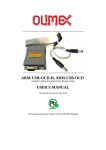
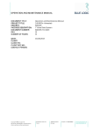
1
A & H Enterprises, Inc. Amflow® 11812 NE 116th Street Kirkland, WA 98034 USA TEL: FAX: www.amflow.com EMAIL: +425.883.4040 +425.823.1962 [email protected] INSTALLATION, OPERATION & SERVICE MANUAL AMFLOW® A2-VACM VALVE ACTUATOR (DIRECT DRIVE) Part Number: 00000222-0501 NOTE Reference the “As Built” data sheet supplied with order for specific actuator configuration. A & H Enterprises, Inc. reserves the right to make modifications and/or improvements to Amflow® products without prior notice. Explanation of Graphic Symbols DANGER AND/OR WARNING The exclamation point within an equilateral triangle surrounded by red is intended to alert the user to the presence of important operating and maintenance instructions that may cause personal injury or harm to the system. CAUTION AND/OR IMPORTANT The exclamation point within an equilateral triangle that is solid yellow with an exclamation point is intended to alert the user to use caution or contains important information. Copyright© 2015 A & H Enterprises, Inc. All rights reserved US & INTERNATIONAL PATENTS PENDING 00000222-0904-000 * Rev. C, 07/15 Page 1 of 35 AMFLOW® A2 VACM Installation, Operation & Service Manual TABLE OF CONTENTS SECTION 1: INFORMATION ......................................................................................................................................................................................... 4 1.01 DESCRIPTION................................................................................................................................................................................................... 4 1.02 DESIGN FEATURES.......................................................................................................................................................................................... 4 1.03 MECHANICAL FEATURES ................................................................................................................................................................................ 4 1.04 COMMUNICATION PROTOCOLS ...................................................................................................................................................................... 4 1.05 SAFETY INFORMATION.................................................................................................................................................................................... 5 1.06 ASSEMBLY VIEW .............................................................................................................................................................................................. 5 1.07 GA DRAWING.................................................................................................................................................................................................... 6 1.08 FULL VIEW ........................................................................................................................................................................................................ 7 1.09 EXPLODED VIEW: Basic .................................................................................................................................................................................. 8 1.09a BOM: Basic ..................................................................................................................................................................................................... 8 1.10 EXPLODED VIEW: Detailed .............................................................................................................................................................................. 9 1.10a BOM .............................................................................................................................................................................................................. 10 1.11 ASSEMBLY VIEW: Adaptor/Clutch Assembly ................................................................................................................................................ 12 1.11a EXPLODED VIEW: Adaptor/Clutch Assembly ................................................................................................................................................ 12 1.11b EXPLODED VIEW: Adaptor/Clutch Assembly................................................................................................................................................ 12 1.12 CUTAWAY VIEW: Detailed Clutch Assembly ................................................................................................................................................ 13 1.12a EXPLODED VIEW: Detailed Clutch Assembly ................................................................................................................................................ 13 1.12b BOM: Detailed Clutch Assembly .................................................................................................................................................................... 14 1.13 PANEL MOUNT: Cut-out Dimensions .............................................................................................................................................................. 15 SECTION 2: INSTALLATION: Actuator ..................................................................................................................................................................... 16 2.01 INSTALLATION PRECAUTIONS: Actuator ...................................................................................................................................................... 16 2.02 INSTALLATION: Tools ..................................................................................................................................................................................... 16 2.03 INSTALLATION PROCEDURE: Horizontal Panel Mount................................................................................................................................... 16 2.04 INSTALLATION PROCEDURE: Vertical Panel Mount....................................................................................................................................... 17 SECTION 3: INSTALLATION: Valve ........................................................................................................................................................................... 18 3.01 INSTALLATION PRECAUTIONS: Valve........................................................................................................................................................... 18 3.02 INSTALLATION PROCEDURE: Valve to Actuator ......................................................................................................................................... 19 SECTION 4: SERVICE: Valve Removal ..................................................................................................................................................................... 21 SECTION 5: SERVICE: Adjustments ......................................................................................................................................................................... 22 5.01 CHECK TORQUE ............................................................................................................................................................................................ 22 5.02 TORQUE ADJUSTMENT ................................................................................................................................................................................. 23 SECTION 6: SERVICE: REPLACEMENTS - Gaskets ................................................................................................................................................. 24 6.01 REPLACMENT: Mounting Plate Gasket .......................................................................................................................................................... 24 6.02 REPLACMENT: EEx de Cover Gasket ............................................................................................................................................................ 25 SECTION 7: SERVICE: REPLACEMENTS ................................................................................................................................................................. 26 7.01 REPLACEMENT: Set Screw ............................................................................................................................................................................ 26 7.02 REPLACEMENT: Drive Pin.............................................................................................................................................................................. 26 7.03 REPLACEMENT: Circuit Board ........................................................................................................................................................................ 26 Copyright© 2015 A & H Enterprises, Inc. All rights reserved US & INTERNATIONAL PATENTS PENDING 00000222-0904-000 * Rev. C, 09/15 Page 2 of 35 AMFLOW® A2 VACM Installation, Operation & Service Manual TABLE OF CONTENTS SECTION 8: SERVICE: Clutch Assembly - Removal & Disassembly ....................................................................................................................... 27 8.01 CLUTCH ASSEMBLY: Removal ...................................................................................................................................................................... 27 8.02 CLUTCH ASSEMBLY: Disassembly................................................................................................................................................................. 27 SECTION 9: RE-ASSEMBLY: Clutch Assembly ........................................................................................................................................................ 29 SECTION 10: RE-ATTACH VALVE TO ACTUATOR.................................................................................................................................................... 31 SECTION 11: TROUBLESHOOTING ........................................................................................................................................................................... 32 11.01 No Power ....................................................................................................................................................................................................... 32 11.02 Torque Slippage ............................................................................................................................................................................................. 32 11.03 Unable to Obtain Newton Meter Reading......................................................................................................................................................... 32 11.04 Broken Drive Pin ............................................................................................................................................................................................ 32 11.05 Inaccurate Turn Count - Valve ........................................................................................................................................................................ 32 11.06 Clutch Assembly Slippage .............................................................................................................................................................................. 32 11.07 Valve Not Fully Engaged in Clutch Assembly .................................................................................................................................................. 32 11.08 Handle Torque Adjustment ............................................................................................................................................................................. 32 STANDARDS & CERTIFICATIONS .............................................................................................................................................................................. 33 LIMITED WARRANTY .................................................................................................................................................................................................. 34 END OF SECTION Copyright© 2015 A & H Enterprises, Inc. All rights reserved US & INTERNATIONAL PATENTS PENDING 00000222-0904-000 * Rev. C, 09/15 Page 3 of 35 AMFLOW® A2 VACM Installation, Operation & Service Manual INFORMATION SECTION 1: INFORMATION 1.01 DESCRIPTION ® ® The Amflow A2-VACM Actuator is a direct drive actuator designed to accommodate a variety of Amflow products in hazardous area usage. Product compatibility includes; AM7 Series, AM8 and AM11A flow control valves and the PR7 Series and PR-HF-SSSP back pressure regulators . Once Amflow® A2-VACM Actuator is installed the valve is screwed onto the TAPER RING (Item 2.2) and locked into place with a 6 mm set screw. The Inlet and Outlet ports of valve will then need to be connected to the system. An optional mounting bracket is available. 1.02 DESIGN FEATURES Normal module operation includes valve position, current limit, pressure & flow feedback. Low maintenance. Environmentally sealed. 1.03 MECHANICAL FEATURES ATEX Certification: DNV 2007 OSL ATEX-1498 Certification Category: II 2G Ex de IIC T4 Degree of Protection: IP66 Weight: 28.5 lbs. (13 Kg) Optional Cable Glands: M20 x 1.5 Amflow® A2-VACM Actuator: Electrical Specifications Motor A2-VACM 00000222-0501-016 DC Gear Watts 24 VDC 30 Watts Max. Operating Current 1.25 amps (continuous) Max In-Rush Current 3.0 amps Manual Override No Communication Industrial Ethernet Hart / 4-20mA H1 FOUNDATION fieldbus Modbus RTU / RS485 Modbus TCP 1.04 COMMUNICATION PROTOCOLS Circuit board: Main motherboard with interchangeable daughter boards. Remote access from host computer for control, monitoring, and configuration. Available Communication Protocols: INDUSTRIAL ETHERNET HART/4-20mA H1 FOUNDATION fieldbus MODBUS RTU / RS485 MODBUS TCP Ethernet Protocol: IEEE 802.3 - 10T/100T These protocols provide ease of use in the field with their own embedded web pages eliminating third party communication devices. Refer to the Circuit Board Manual provided with order for information and issues regarding communication. Copyright© 2015 A & H Enterprises, Inc. All rights reserved US & INTERNATIONAL PATENTS PENDING 00000222-0904-000 * Rev. C, 09/15 Page 4 of 35 AMFLOW® A2 VACM Installation, Operation & Service Manual INFORMATION 1.05 SAFETY INFORMATION SAFETY INFORMATION Follow IEC when working with electrical units. When handling product avoid dropping, damaging, or submerging. Ensure proper wiring. Person(s) handling circuit board should be properly grounded. Do not open unit while energized. 1.06 ASSEMBLY VIEW AMFLOW® A2-VACM Actuator Shown without Clutch Assembly or Mounting Bracket AMFLOW® A2-VACM Actuator Shown with Clutch Assembly and Mounting Bracket AMFLOW® A2-VACM Actuator Transparent View Copyright© 2015 A & H Enterprises, Inc. All rights reserved US & INTERNATIONAL PATENTS PENDING 00000222-0904-000 * Rev. C, 09/15 Page 5 of 35 AMFLOW® A2 VACM Installation, Operation & Service Manual INFORMATION 1.07 GA DRAWING AMFLOW® A2-VACM ACTUATOR Shown Fully Assembled with AM7B Flow Control Valve Copyright© 2015 A & H Enterprises, Inc. All rights reserved US & INTERNATIONAL PATENTS PENDING 00000222-0904-000 * Rev. C, 09/15 Page 6 of 35 AMFLOW® A2 VACM Installation, Operation & Service Manual INFORMATION 1.08 FULL VIEW Ex MOTOR HOUSING ASSEMBLY DC MOTOR MOTOR GASKET CLUTCH ASSEMBLY CIRCUIT BOARD EExe COVER EExe GASKET TAPER RING MOUNTING BRACKET LINE BUSHINGS EExe CARRIER DIN TERMINAL BLOCK Copyright© 2015 A & H Enterprises, Inc. All rights reserved US & INTERNATIONAL PATENTS PENDING 00000222-0904-000 * Rev. C, 09/15 Page 7 of 35 AMFLOW® A2 VACM Installation, Operation & Service Manual INFORMATION 1.09 EXPLODED VIEW: Basic 1 2.4 2.1 2.3 2.5 2.2 1.09a BOM: Basic ITEM PART DESCRIPTION QTY 1 00000471-0401-000 Ex Housing Assy 1 2.1 00000994-0301-000 Adapter Block 1 2.2 00000995-0301-000 Taper Ring 1 2.3 00000999-0301-000 Mounting Plate 1 2.4 00001500-7306-008-00 Set Screw 3 2.5 00001500-7006-020-00 M6x20 SHCS 4 Copyright© 2015 A & H Enterprises, Inc. All rights reserved US & INTERNATIONAL PATENTS PENDING 00000222-0904-000 * Rev. C, 09/15 Page 8 of 35 AMFLOW® A2 VACM Installation, Operation & Service Manual INFORMATION 1.10 EXPLODED VIEW: Detailed Copyright© 2015 A & H Enterprises, Inc. All rights reserved US & INTERNATIONAL PATENTS PENDING 00000222-0904-000 * Rev. C, 09/15 Page 9 of 35 AMFLOW® A2 VACM Installation, Operation & Service Manual INFORMATION 1.10a BOM ITEM # PART # DESCRIPTION QTY 1 00000471-0401-000 Ex Housing Assy 1 1.1 00000469-0301-000 EEx de Carrier 1 1.2 00000470-0301-000 Bell Housing 1 1.3 00000328-0301-000 Bearing 1 1.4 00000327-0301-000 Circlip 1 1.5 00000326-0301-000 Shaft Adaptor 1 1.6 00000473-0301-000 Motor Plate Adaptor 1 1.7 00001410-0401-001 DC Motor Assy, w/Circuit Board 1 1.7.1 00000342-0301-000 DC Motor 1 1.7.2 00001130-0301-000 M3 x 5 M/F Hex Spacer 4 1.7.3 00001133-0301-XXX 3 mm x 70 mm Stud 4 1.7.4 00001132-0301-000 3 mm x 8 mm OAL Hex Nut 4 1.7.5 00001127-0301-007 Connector: 7 Pin 1 1.8 00001555-2153-000 Carrier O-Ring 1 1.9 00001500-7005-010-00 M5 x 10 SHCS 9 1.1 00000498-0301-000 15 mm DIN Rail 1 1.11 00000499-0301-002 Line Bushing: 7 Wire - 16 mm 1 1.12 00000501-0301-000 EEx de Cover 1 1.13 00000502-0301-000 EEx de Gasket 1 1.14 00000503-0301-000 DIN Terminal Block 13 1.15 00000494-0301-000 Safety Clamp 1 1.16 00000337-0301-000 Drive Pin 1 1.17 00001500-7105-008-00 M5 x 8 Panhead 2 1.18 00001500-7104-006-00 M4 x 6 Panhead 3 1.19 00001500-7005-020-00 M5 x 20 SHCS 4 1.2 00001127-0301-009 Connector: 9 Pin 1 1.21 00001139-0301-000 Fuse Holder 1 1.22 00001381-0401-000 Circuit Board Assy 1 1.23 00000503-0301-001 DIN Earth Terminal 2 1.24 00001708-0301-000 Circuit Board 1 1.25 00000499-0301-003 Line Bushing: 9 Wire - 16 mm 1 Copyright© 2015 A & H Enterprises, Inc. All rights reserved US & INTERNATIONAL PATENTS PENDING 00000222-0904-000 * Rev. C, 09/15 Page 10 of 35 AMFLOW® A2 VACM Installation, Operation & Service Manual INFORMATION ITEM # PART # DESCRIPTION QTY 2 00001000-0401-000 Adapter Housing / Clutch Assy 1 2.1 00000994-0301-000 Adapter Block 1 2.2 00000995-0301-000 Taper Ring 1 2.3 00000999-0301-000 Mounting Plate 1 2.4 00001500-7306-008-00 Set Screw 3 2.5 00001500-7006-020-00 M6x20 SHCS 4 00000286-0301-000 Mounting Gasket 1 3 Copyright© 2015 A & H Enterprises, Inc. All rights reserved US & INTERNATIONAL PATENTS PENDING 00000222-0904-000 * Rev. C, 09/15 Page 11 of 35 AMFLOW® A2 VACM Installation, Operation & Service Manual INFORMATION 1.11 ASSEMBLY VIEW: Adaptor/Clutch Assembly 1.11a EXPLODED VIEW: Adaptor/Clutch Assembly 1.11b EXPLODED VIEW: Adaptor/Clutch Assembly Copyright© 2015 A & H Enterprises, Inc. All rights reserved US & INTERNATIONAL PATENTS PENDING 00000222-0904-000 * Rev. C, 09/15 Page 12 of 35 AMFLOW® A2 VACM Installation, Operation & Service Manual INFORMATION 1.12 CUTAWAY VIEW: Detailed Clutch Assembly 1.12a EXPLODED VIEW: Detailed Clutch Assembly Copyright© 2015 A & H Enterprises, Inc. All rights reserved US & INTERNATIONAL PATENTS PENDING 00000222-0904-000 * Rev. C, 09/15 Page 13 of 35 AMFLOW® A2 VACM Installation, Operation & Service Manual INFORMATION 1.12b BOM: Detailed Clutch Assembly ITEM # PART # DESCRIPTION QTY 2 00001000-0401-000 Adapter Housing / Clutch Assy 1 2.1 00000994-0301-000 Adapter Block 1 2.2 00000995-0301-000 Taper Ring 1 2.3 00000999-0301-000 Mounting Plate 1 2.4 00001500-7306-008-00 Set Screw 3 2.5 00001500-7006-020-00 M6x20 SHCS 4 2.6 00001214-0401-000 Clutch Assy 1 2.6.1 00001156-0401-000 Clutch Housing 1 2.6.1.1 00000996-0301-000 Clutch Barrel 1 2.6.1.2 00000998-0301-000 FC Shaft 1 2.6.2 00000246-0301-000 Clutch Ring 2 2.6.3 00000249-0301-000 Clutch Washer 2 2.6.4 00001600-1000-050-00-0505 Belleville Spring 4 2.6.5 00000997-0301-000 FC Loader 1 2.6.6 00001003-0301-000 Lock Ring 1 2.6.7 00000246-0301-001 Modified Clutch Ring 1 2.6.8 00001001-0301-000 Tension Ring 1 2.6.9 00001500-7304-006-00 M4 x 6 Set Screw 3 END OF SECTION Copyright© 2015 A & H Enterprises, Inc. All rights reserved US & INTERNATIONAL PATENTS PENDING 00000222-0904-000 * Rev. C, 09/15 Page 14 of 35 AMFLOW® A2 VACM Installation, Operation & Service Manual INFORMATION 1.13 PANEL MOUNT: Cut-out Dimensions Vertical mount A2-VACM Actuator using two 6.35 mm holes located on bottom portion of MOUNTING PLATE (ITEM 2.3). Horizontal mount A2-VACM Actuator using four 6.35 mm holes located on vertical portion of MOUNTING PLATE (ITEM 2.3). Ref. Diagram 1 HORIZONTL MOUNT VERTICAL MOUNT DIAGRAM 1: A2-VACM Actuator MOUNTING PANEL END OF SECTION Copyright© 2015 A & H Enterprises, Inc. All rights reserved US & INTERNATIONAL PATENTS PENDING 00000222-0904-000 * Rev. C, 09/15 Page 15 of 35 AMFLOW® A2 VACM Installation, Operation & Service Manual INSTALLATION: Actuator SECTION 2: INSTALLATION: Actuator 2.01 INSTALLATION PRECAUTIONS: Actuator Be careful when handling actuator, if dropped internal electronics may be damaged. Do not change manufacturer’s torque settings or unit may function incorrectly. However, instructions have been supplied for torque setting adjustments if needed. WARNING Failure to set torque correctly may cause actuator to function improperly! 2.02 INSTALLATION: Tools 4 mm, 6 mm Allen Wrench Flathead Screwdriver 2.03 INSTALLATION PROCEDURE: Horizontal Panel Mount Copyright© 2015 A & H Enterprises, Inc. All rights reserved US & INTERNATIONAL PATENTS PENDING 00000222-0904-000 * Rev. C, 09/15 Page 16 of 35 AMFLOW® A2 VACM Installation, Operation & Service Manual INSTALLATION: Actuator 2.04 INSTALLATION PROCEDURE: Vertical Panel Mount END OF SECTION Copyright© 2015 A & H Enterprises, Inc. All rights reserved US & INTERNATIONAL PATENTS PENDING 00000222-0904-000 * Rev. C, 09/15 Page 17 of 35 AMFLOW® A2 VACM Installation, Operation & Service Manual INSTALLATION: Valve SECTION 3: INSTALLATION: Valve 3.01 INSTALLATION PRECAUTIONS: Valve Good system design is critical to the optimum operation of the Amflow® Valves. At a minimum, the design should include: Isolation valves located near inlet and outlet ports of the Amflow® Valve. (The outlet isolation valve is normally a three-way valve that can be incorporated into the calibration loop.) IMPORTANT: The importance of proper media filtering cannot be overstated. It is strongly recommended that filters be placed on both the suction side and the pressure side of pump. It is not unusual to have individual filters inline for each valve. The recommended micron size of the high-pressure filter is somewhat dependent on the specific configuration of any given Amflow® Valve. However, a 50-micron filter size is generally adequate for most applications. The system design should take into consideration that materials which come into contact with the injected media should not contribute to foreign matter entering into the system. This means it is unwise to use material that can be easily corroded, such as mild steels. A check valve located on the outlet side of each Amflow® Valve is strongly recommended. There are a number of reasons for this: The first and most obvious is for safety considerations. The second is to prevent a massive backflow through the Amflow® Valve. This backflow can occur if there is a pump failure or some other system failure that would cause a loss of positive pressure across the Amflow® Valve. The Amflow® Valve is designed to accommodate some backflow conditions; however, piston seal damage can occur if backflow is excessive. The seal is designed to fail under certain conditions in order to prevent damage that is more serious to the valve. NOTE: Reference Installation, Operation & Service manual supplied with valve order for information Copyright© 2015 A & H Enterprises, Inc. All rights reserved US & INTERNATIONAL PATENTS PENDING 00000222-0904-000 * Rev. C, 09/15 Page 18 of 35 AMFLOW® A2 VACM Installation, Operation & Service Manual INSTALLATION: Valve 3.02 INSTALLATION PROCEDURE: Valve to Actuator Step 1 Remove panel lock. NOTE Adjustment Knob & Panel Lock shipped with valve are not intended for this installation. Install only if needed for manual operation. Step 2 Attach TAPER RING (ITEM 2.2) and thread onto valve. NOTE AM7 Series, AM8 Series and PR7 Series use a 33 mm TAPER RING (ITEM 2.2). AM9A and PR-HF-SSSP use a 44 mm TAPER RING (ITEM 2.2) Step 3 Insert TAPER RING (ITEM 2.2) into ADAPTER BLOCK (ITEM 2.1). Secure in place using SET SCREWS (ITEM 2.4). Copyright© 2015 A & H Enterprises, Inc. All rights reserved US & INTERNATIONAL PATENTS PENDING 00000222-0904-000 * Rev. C, 09/15 Page 19 of 35 AMFLOW® A2 VACM Installation, Operation & Service Manual INSTALLATION: Valve 3.02 INSTALLATION PROCEDURE: Valve to Actuator, continued A2-VACM ACTUATO R MOUNTING PLATE ADAPTER BLOCK TAPER RING (3) SET SCREWS AM7B VALVE (4) M6 X 20 SHCS END OF SECTION Copyright© 2015 A & H Enterprises, Inc. All rights reserved US & INTERNATIONAL PATENTS PENDING 00000222-0904-000 * Rev. C, 09/15 Page 20 of 35 AMFLOW® A2 VACM Installation, Operation & Service Manual SERVICE: Valve Removal SECTION 4: SERVICE: Valve Removal BEFORE CARRYING OUT NEXT ACTIONS 1. Close down system or isolate valve to be removed. 2. Vent all pressure. 4.01 VALVE REMOVAL FROM SYSTEM Step 1 Disconnect tubing from Inlet and Outlet ports. Step 2 Loosen three(3) 6 mm SET SCREWS (Item 2.4) located on ADAPTOR BLOCK (Item 2.1), using a 3 mm hex head wrench. Ref. FIGURE 1 FIGURE 1 Step 3 Remove valve. 4.02 OPENING VALVE PROCEDURE For maintenance and service of valve, please reference the Installation, Operation & Service Manual for the specific valve provided with order. END OF SECTION Copyright© 2015 A & H Enterprises, Inc. All rights reserved US & INTERNATIONAL PATENTS PENDING 00000222-0904-000 * Rev. C, 09/15 Page 21 of 35 AMFLOW® A2 VACM Installation, Operation & Service Manual SERVICE: Adjustments SECTION 5: SERVICE: Adjustments 5.01 CHECK TORQUE Step 1 Remove CLUTCH ASSEMBLY(Item 2.6) from SHAFT ADAPTER (Item 1.5) by pulling the two sections apart. Step 2 Hold CLUTCH ASSEMBLY (Item 2.6) securely. Step 3 Using a torque wrench, with a fitted 6 mm hex drive, check to ensure spinning torque is between 6.7 and 9 newton meters (60-80 in lbs.). FIGURE 1 FIGURE 2 Ref. FIGURE 1 Ref FIGURE 2,3, & 4 FIGURE 3 FIGURE 4 END OF SECTION Copyright© 2015 A & H Enterprises, Inc. All rights reserved US & INTERNATIONAL PATENTS PENDING 00000222-0904-000 * Rev. C, 09/15 Page 22 of 35 AMFLOW® A2 VACM Installation, Operation & Service Manual SERVICE: Adjustments 5.02 TORQUE ADJUSTMENT (if needed) Step 1 Remove three (3) M4x6 SET SCREWS (Item 2.6.9). Step 2 Using Torque Tool (Part 1412-1000-000) (Ref. Appendix A) remove LOCK RING (Item 2.6.6). Step 3 Using Torque Tool (Part 1412-1000-000) (Ref. Appendix A) adjust TENSION RING (Item 2.6.8). Clockwise to increase torque or counter-clockwise to decrease torque to achieve the proper torque setting between 6.7 and 9 newton meters (60-80 in lbs.). Step 4 Confirm torque. END OF SECTION Copyright© 2015 A & H Enterprises, Inc. All rights reserved US & INTERNATIONAL PATENTS PENDING 00000222-0904-000 * Rev. C, 09/15 Page 23 of 35 AMFLOW® A2 VACM Installation, Operation & Service Manual SERVICE: Replacements SECTION 6: SERVICE: REPLACEMENTS - Gaskets 6.01 REPLACMENT: Mounting Plate Gasket Step 1 Locate MOUNTING PLATE (Item 2.3). Step 2 Remove four (4) M6X20 SHCS (Item 2.5) attached to ADAPTER BLOCK (Item 2.1) located on front side of MOUNTING PLATE (Item 2.3). Step 3 Locate the side of the MOUNTING PLATE with laser markings, then on opposite side: Remove MOUNTING GASKET (Item 3). Aligning holes attach new MOUNTING GASKET (Item 3) onto backside of MOUNTING PLATE (Item 2.3). Press into place. Step 4 Re-attach ADAPTOR BLOCK (Item 1.2) and MOUNTING PLATE (Item 2.3). END OF SECTION Copyright© 2015 A & H Enterprises, Inc. All rights reserved US & INTERNATIONAL PATENTS PENDING 00000222-0904-000 * Rev. C, 09/15 Page 24 of 35 AMFLOW® A2 VACM Installation, Operation & Service Manual SERVICE: Replacements 6.02 REPLACMENT: EEx de Cover Gasket Step 1 Remove EEx de COVER (Item 1.12), by unscrewing four (4) M5X20 SCREWS (Item 1.19). Step 2 Remove and replace EEx de GASKET (Item 1.13) to EEx de COVER (Item 1.12). Step 3 Re-attach EEx de COVER (Item 1.12). END OF SECTION Copyright© 2015 A & H Enterprises, Inc. All rights reserved US & INTERNATIONAL PATENTS PENDING 00000222-0904-000 * Rev. C, 09/15 Page 25 of 35 AMFLOW® A2 VACM Installation, Operation & Service Manual SERVICE: Replacements SECTION 7: SERVICE: REPLACEMENTS 7.01 REPLACEMENT: Set Screw Step 1 Remove and replace three (3) SET SCREWS (Item 2.4) located on ADAPTOR BLOCK (Item 2.1), using a 4 mm Allen head wrench. 7.02 REPLACEMENT: Drive Pin Step 1 Insert DRIVE PIN (Item 1.16) onto SHAFT ADAPTOR (Item 1.5). Ref. FIGURE 1 & 2 The open side of DRIVE PIN (Item 1.16) must face away from EEx de CARRIER (Item 1.1). Using a punch and mallet insert DRIVE PIN (Item 1.16) so there are even lengths of the DRIVE PIN on both sides of SHAFT ADAPTOR (Item 1.5). FIGURE 1 FIGURE 2 7.03 REPLACEMENT: Circuit Board In the event of circuit board replacement and/or program updates, a new circuit board will need to be installed. Please contact manufacturer for instructions. END OF SECTION Copyright© 2015 A & H Enterprises, Inc. All rights reserved US & INTERNATIONAL PATENTS PENDING 00000222-0904-000 * Rev. C, 09/15 Page 26 of 35 AMFLOW® A2 VACM Installation, Operation & Service Manual SERVICE: Replacements SECTION 8: SERVICE: Clutch Assembly - Removal & Disassembly 8.01 CLUTCH ASSEMBLY: Removal Step 1 Remove CLUTCH ASSEMBLY (Item 2.6) from SHAFT ADAPTOR (Item 1.5). FIGURE 1 Ref. FIGURE 1 & 2 FIGURE 2 8.02 CLUTCH ASSEMBLY: Disassembly Step 1 Using a hex wrench, loosen and remove three (3) M4X6 SET SCREWS (Item 2.6.9). Ref. FIGURE 3 FIGURE 3 Step 2 Remove LOCK RING (Item 2.6.6), using Torque Tool (Part 1412-1000-000) (Ref. Appendix A). TORQUE TOOL Ref. FIGURE 5 & 6 TORQUE TOOL LOCK RING (Item 2.6.6) FIGURE 5 FIGURE 6 Copyright© 2015 A & H Enterprises, Inc. All rights reserved US & INTERNATIONAL PATENTS PENDING 00000222-0904-000 * Rev. C, 09/15 Page 27 of 35 AMFLOW® A2 VACM Installation, Operation & Service Manual SERVICE: Replacements 8.02 CLUTCH ASSEMBLY: Disassembly, continued Step 3 Using Torque Tool, remove TENSION RING (Item 2.6.8). Ref. FIGURE 7 TORQUE TOOL TENSION RING (Item 2.6.8) FIGURE 7 Step 4 Remove parts in order: MODIFIED CLUTCH RING (Item 2.6.7) FC LOADER (Item 2.6.5) 1ST CLUTCH RING (Item 2.6.2) 1ST CLUTCH WASHER (Item 2.6.3) BELLEVILLE SPRINGS (Item 2.6.4) (NOTE CONFIGURATION OF SPRINGS) ND 2 CLUTCH WASHER (Item 2.6.3) 2ND CLUTCH RING (Item 2.6.2) MODIFIED CLUTCH RING FC LOADER FIGURE 1 BELLEVILLE FIGURE 2 SPRINGS FIGURE 4 2nd Ref. FIGURE 1 Ref. FIGURE 2 Ref. FIGURE 3 Ref. FIGURE 3 Ref. FIGURE 4 Ref. FIGURE 5 Ref. FIGURE 5 1st CLUTCH RING & WASHER FIGURE 3 CLUTCH WASHER & RING FIGURE 5 Step 5 Replace needed part(s). Step 6 Re-assemble reversing above order. Pay particular attention to order and placement of BELLEVILLE SPRINGS (Item 2.6.4). END OF SECTION Copyright© 2015 A & H Enterprises, Inc. All rights reserved US & INTERNATIONAL PATENTS PENDING 00000222-0904-000 * Rev. C, 09/15 Page 28 of 35 AMFLOW® A2 VACM Installation, Operation & Service Manual SERVICE: Re-Assembly SECTION 9: RE-ASSEMBLY: Clutch Assembly NOTE Reverse Section 5 for all re-assembly work done within CLUTCH ASSEMBLY (Item 2.6). CAUTION IMPROPER ORDER OR PLACEMENT OF BELLEVILLE SPRINGS WILL CAUSE UNIT TO MALFUNCTION. Replace BELLEVILLE SPRINGS (Item 2.6.4) in order as removed. Insert first BELLEVILLE SPRING (Item 2.6.4) concave side up, and then reverse order after, (e.g.… Up, Down, Up). Step 1 Insert TENSION RING (Item 2.6.8). NOTE Use Anti-seize on thread when inserting TENSION RING (Item 2.6.8). Step 2 When adjusting TENSION RING (Item 2.6.8) adjust so there is between 6.7-9 newton meters (60–80 in. lbs) of spinning torque. Using a 6 mm torque wrench, ensure that proper torque specifications have been met. FIGURE 1 Ref. FIGURE 1 & 2 Ref. FIGURE 2 FIGURE 2 Copyright© 2015 A & H Enterprises, Inc. All rights reserved US & INTERNATIONAL PATENTS PENDING 00000222-0904-000 * Rev. C, 09/15 Page 29 of 35 AMFLOW® A2 VACM Installation, Operation & Service Manual SERVICE: Re-Assembly SECTION 9: RE-ASSEMBLY: Clutch Assembly, continued Step 3 Insert LOCK RING (Item 2.6.6). Lock in place with three (3) M4x6 SET SCREWS (Item 2.6.9). Ref. FIGURE 3 Ref. FIGURE 4 NOTE Use Anti-seize on thread when inserting LOCK RING (Item 2.6.6). FIGURE 3 FIGURE 4 Step 4 Place CLUTCH ASSEMBLY onto DRIVE PIN (Item 1.16). Using a rubber or plastic mallet, lightly tap CLUTCH ASSEMBLY (Item 2.6) onto SHAFT ADAPTOR (Item 1.5). Ref. FIGURE 5 Ref. FIGURE 6 IMPORTANT Care must be taken that DRIVE PIN (Item 1.16) is fully seated in groove. FIGURE 5 FIGURE 6 END OF SECTION Copyright© 2015 A & H Enterprises, Inc. All rights reserved US & INTERNATIONAL PATENTS PENDING 00000222-0904-000 * Rev. C, 09/15 Page 30 of 35 AMFLOW® A2 VACM Installation, Operation & Service Manual SERVICE: Valve Re-installation SECTION 10: RE-ATTACH VALVE TO ACTUATOR Step 1 Insert TAPER RING (ITEM 2.2) onto ADAPTER BLOCK (Item 2.1). Secure in place using SET SCREWS (Item 2.4). Step 2 Re-connect the Inlet and Outlet ports of valve to the system. END OF SECTION Copyright© 2015 A & H Enterprises, Inc. All rights reserved US & INTERNATIONAL PATENTS PENDING 00000222-0904-000 * Rev. C, 09/15 Page 31 of 35 AMFLOW® A2 VACM Installation, Operation & Service Manual TROUBLESHOOTING: Actuator SECTION 11: TROUBLESHOOTING 11.01 No Power Issue: Cause: Correction: Actuator not responding. Blown fuse. Check and replace fuse. 11.02 Torque Slippage Issue: Valve not operating. Cause: Incorrect torque setting. Correction #1: Check that there is between 6.8 -9 newton meter (60-80 in. lbs.) rolling torque. 11.03 Unable to Obtain Newton Meter Reading Issue: Unable to get 6.8 newton meter (60 in. lbs.) when adjusting torque. Cause: Worn BELLEVILLE SPRINGS. Correction: Replace BELLEVILLE SPRINGS. 11.04 Broken Drive Pin Issue: Clutch Assembly not turning properly. Cause: Broken DRIVE PIN. Correction: Contact manufacturer. 11.05 Inaccurate Turn Count - Valve Issue: Cause: Cause: Correction #1: Improper valve turn count. Error in valve turn count. Valve not fully opening or closing due to spinning valve. Tighten SET SCREW to secure valve. 11.06 Clutch Assembly Slippage Issue: Cause #1: Cause #2: Correction #1: Correction #2: Unable to obtain proper torque. Improper torque setting. Worn BELLEVILLE SPRINGS. Adjust torque settings. Replace BELLEVUE SPRINGS. 11.07 Valve Not Fully Engaged in Clutch Assembly Issue: Valve not fully engaged into CLUTCH DRIVE SHAFT ASSEMBLY. Cause: Loosen SET SCREW. Correction: Check valve and actuator are assembled correctly. 11.08 Handle Torque Adjustment Issue: Actuator not operating in “Automatic Mode”. Cause: Loosen LOCK NUT. Correction: Loosen LOCK NUT on front of SHAFT ASSEMBLY. Adjust BEARING NUT to desired torque. Re-tighten lock nut. NOTE: Large adjustments to handle torque can affect actuator rolling torque. END OF SECTION Copyright© 2015 A & H Enterprises, Inc. All rights reserved US & INTERNATIONAL PATENTS PENDING 00000222-0904-000 * Rev. C, 09/15 Page 32 of 35 AMFLOW® A2 VACM Installation, Operation & Service Manual STANDARDS & CERTIFICATIONS STANDARDS A&H Enterprises designs its products to meet the applicable ASME, and API standards for valve design and pressure vessels. Products are also CE marked and ATEX approved for Hazardous area installations. MEMBERSHIPS CERTIFICATIONS ATEX DIRECTIVE (94/9/EC) In the interest of safety and quality, A&H Enterprises has certified its Amflow® series of actuators for use in potentially explosive atmospheres as defined by the ATEX Directive (94/9/EC) as Category 2G. ATEX II 2 G Ex de IIC T4 US & INTERNATIONAL PATENTS PENDING To ensure the safety of all parties, only genuine Amflow® parts must be installed in accordance with supplied instructions, good engineering, and construction practices. The actuators must not be modified in any way from the original purchased actuators. The actuators must only be operated in the conditions indicated on product data sheet. This equipment is certified for Group 2 Category II. Equipment should not be used in systems requiring a higher level of certification. Copyright© 2015 A & H Enterprises, Inc. All rights reserved US & INTERNATIONAL PATENTS PENDING 00000222-0904-000 * Rev. C, 09/15 Page 33 of 35 AMFLOW® A2 VACM Installation, Operation & Service Manual WARRANTY LIMITED WARRANTY Each Amflow® product is warranted to be free from defects in material and workmanship under normal use and service. The warranty period is three (3) years and begins on the date of original purchase. This warranty extends only to the original buyer and does not apply to any product which, in A & H Enterprises’ opinion, has been misused, altered, neglected, contaminated, damaged by accident or abnormal conditions of operation or handling. At A & H Enterprises’ option, the A & H Enterprises’ warranty obligation is limited to the replacement or repair of a defective product that is returned to A & H Enterprises within the warranty period. Merchandise returned to A & H Enterprises within the warranty period which, in A & H Enterprises’ opinion, is defective by accident, improper operation or improper handling shall be subject to a charge for repair. Merchandise, free from defects, returned to A & H Enterprises shall be subjected to a 20% restocking fee within thirty (30) days of the purchase date. Written authorization is required for all merchandise returned to A & H Enterprises. To obtain warranty service, contact A & H Enterprises to obtain return authorization information. Then send the product to A & H Enterprises with a description of the difficulty, transportation and insurance prepaid. A & H Enterprises assumes no risk for damage in transit. Following warranty repair, the product will be returned to Buyer, transportation and insurance prepaid. If A & H Enterprises determines that failure was caused by neglect, misuse, contamination, alteration, accident, or abnormal condition of operation or handling, A & H Enterprises will provide an estimate of repair costs and obtain authorization before commencing the work. Following repair, the product will be returned to the Buyer, transportation and insurance prepaid, and the Buyer will be billed for the repairs and the return transportation and insurance charges. THIS WARRANTY IS BUYER’S SOLE AND EXCLUSIVE REMEDY AND IS IN LIEU OF ALL OTHER WARRANTIES, EXPRESS OR IMPLIED, INCLUDING BUT NOT LIMITED TO, ANY IMPLIED WARRANTY OR MERCHANTABILITY OR FITNESS FOR A PARTICULAR PURPOSE. A & H ENTERPRISES SHALL NOT BE LIABLE FOR ANY SPECIAL, INDIRECT, INCIDENTAL OR CONSEQUENTIAL DAMAGES OR LOSSES, ARISING FROM ANY CAUSE OR THEORY. Since some countries or states do not allow limitation of the term of an implied warranty, or exclusion or limitation of incidental or consequential damages, the limitations and exclusions of this warranty may not apply to every buyer. If any provision of the Warranty is held invalid or unenforceable by a court or other decision-maker of competent jurisdiction, such holding will not affect the validity or enforceability of any other provision. Copyright© 2015 A & H Enterprises, Inc. All rights reserved US & INTERNATIONAL PATENTS PENDING 00000222-0904-000 * Rev. C, 09/15 Page 34 of 35 AMFLOW® A2 VACM Installation, Operation & Service Manual REPRESENTATIVES AMFLOW® NORGE Norway, Sweden, Denmark, Netherlands, Germany, U.K., Italy Prinsens vei 12 4315 Sandnes Norway Telephone: Fax: E-mail: +47.922.16.656 +47.520.00.591 [email protected] AMFLOW CONTROLS ASIA SDN. BHD. Malaysia, Indonesia, Singapore, India, Thailand, Vietnam No. 1701 Block 1, TTDI ADINA Jalan Judo 13/45, Seksyen 13 40675 Shah Alam, Selangor Malaysia Telephone: Mobile: E-mail: (+603) 5523.8418 (+6012) 3323.118 [email protected] SUDIFLOW INTERGRATED SERVICES, LTD. Nigeria 25 Elelenwo Road Port Harcourt, Nigeria Telephone: E-mail: +234.803.309.1405, +705.679.4894 [email protected] PROPRIETARY DISCLOSURE NOTICE: This material contains proprietary information belonging to A & H Enterprises, Inc. and may not be disclosed, in whole or in part, without express written permission of A & H Enterprises, Inc. A & H Enterprises, Inc. Amflow® Copyright© 2015 A & H Enterprises, Inc. All rights reserved 11812 NE 116th Street Kirkland, WA 98034 USA www.amflow.com 00000222-0904-000 * Rev. C, 09/15 TEL: FAX: EMAIL: +425.883.4040 +425.823.1962 [email protected] Page 35 of 35