1
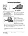
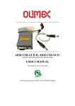
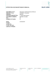
A & H Enterprises, Inc. Amflow® 11812 NE 116th Street Kirkland, WA 98034 USA TEL: FAX: www.amflow.com EMAIL: +425.883.4040 +425.823.1962 [email protected] INSTALLATION & SERVICE MANUAL AMFLOW® AM7B-SSSP Flow Control Valve Part Number: 00000576-0501 NOTE Reference the “As Built” data sheet supplied with order for specific valve configuration. Explanation of Graphic Symbols DANGER AND/OR WARNING The exclamation point within an equilateral triangle surrounded by red is intended to alert the user to the presence of important operating and maintenance instructions that may cause personal injury or harm to the system. CAUTION AND/OR IMPORTANT The exclamation point within an equilateral triangle that is solid yellow with an exclamation point is intended to alert the user to use caution or contains important information. Copyright© 2015 A & H Enterprises, Inc. All rights reserved US PATENTS: 5,427,139 * 5,494,070 * 6,189,564,B1 * EU PATENT 1110132 00000576-0904-000 * Rev. B, 09/15 Page 1 of 54 AMFLOW® AM7B-SSSP Installation & Service Manual TABLE OF CONTENTS SECTION 1: INFORMATION ......................................................................................................................................................................................... 4 1.01 DESCRIPTION................................................................................................................................................................................................... 4 1.02 DESIGN FEATURES.......................................................................................................................................................................................... 5 1.03 SAFETY INFORMATION.................................................................................................................................................................................... 5 1.04 GA DRAWING: Sub-Sea ................................................................................................................................................................................... 6 1.04a CUT-AWAY VIEW – Full Assembly: Sub-Sea ................................................................................................................................................... 7 1.04b EXPLODED VIEW – Full Assembly: Sub-Sea .................................................................................................................................................. 8 1.04c BOM – Full Assembly: Sub-Sea ........................................................................................................................................................................ 9 1.05 SUB-SEA: ROV Bucket with AM7B-SSSP........................................................................................................................................................ 11 1.05a SUB-SEA TRANSPARENT VIEW: ROV Bucket with AM7B-SSSP................................................................................................................... 12 1.05b SUB-SEA CUT-AWAY VIEW: ROV Bucket with AM7B-SSSP .......................................................................................................................... 13 1.06 GA DRAWING: Top Side ............................................................................................................................................................................... 14 1.06a CUT-AWAY VIEW – Full Assembly: Top-Side ................................................................................................................................................ 15 1.06b EXPLODED VIEW – Full Assembly: Top Side ................................................................................................................................................ 16 1.06c BOM – Full Assembly: Top Side...................................................................................................................................................................... 17 1.07 CUT-AWAY VIEW: Sub-Assembly – Upper Body ........................................................................................................................................... 19 1.07a EXPLODED VIEW: Sub-Assembly – Upper Body ........................................................................................................................................... 19 1.07b BOM: Sub-Assembly – Upper Body ............................................................................................................................................................... 19 1.08 CUT-AWAY VIEW: Sub-Assembly – Upper Piston.......................................................................................................................................... 20 1.08a EXPLODED VIEW: Sub-Assembly – Upper Piston ......................................................................................................................................... 20 1.08b BOM: Sub-Assembly – Upper Piston.............................................................................................................................................................. 20 1.09 CUT-AWAY VIEW: Sub-Assembly – Center Body ......................................................................................................................................... 21 1.09a EXPLODED VIEW: Sub-Assembly – Center Body .......................................................................................................................................... 21 1.09b BOM: Sub-Assembly – Center Body .............................................................................................................................................................. 21 1.10 CUT-AWAY VIEW: Sub-Assembly – Outlet Body............................................................................................................................................ 22 1.10a EXPLODED VIEW: Sub-Assembly – Outlet Body ........................................................................................................................................... 22 1.10b BOM: Sub-Assembly – Outlet Body................................................................................................................................................................ 22 1.11 CUT-AWAY VIEW: Sub-Assembly – Lower Piston.......................................................................................................................................... 23 1.11a EXPLODED VIEW: Sub-Assembly – Lower Piston ......................................................................................................................................... 23 1.11b BOM: Sub-Assembly – Lower Piston.............................................................................................................................................................. 23 1.12 CUT-AWAY VIEW: Panel Mount – Top Side .................................................................................................................................................... 24 1.12a PANEL MOUNT: Cut-out Dimensions ............................................................................................................................................................ 25 SECTION 2: VALVE INSTALLATION .......................................................................................................................................................................... 26 2.01 INSTALLATION PROCEDURE: SUB-SEA ....................................................................................................................................................... 26 2.01a INSTALLATION PROCEDURE: TOP SIDE .................................................................................................................................................... 26 2.02 INSTALLATION PRECAUTIONS ..................................................................................................................................................................... 27 Copyright© 2015 A & H Enterprises, Inc. All rights reserved US PATENTS: 5,427,139 * 5,494,070 * 6,189,564,B1 * EU PATENT 1110132 00000576-0904-000 * Rev. B, 09/15 Page 2 of 54 AMFLOW® AM7B-SSSP Installation & Service Manual TABLE OF CONTENTS SECTION 3: START-UP PROCEDURE – TOP SIDE.................................................................................................................................................... 28 3.01 START-UP PROCEDURE ................................................................................................................................................................................ 28 SECTION 4: OPERATION ........................................................................................................................................................................................... 29 SECTION 5: MAINTENANCE ...................................................................................................................................................................................... 30 5.01 VALVE REMOVAL FROM SYSTEM ................................................................................................................................................................. 30 5.02 OPENING PROCEDURE: Valve ...................................................................................................................................................................... 31 SECTION 6: REPLACEMENTS ................................................................................................................................................................................... 33 6.01 REPLACEMENT: Upper Seat .......................................................................................................................................................................... 33 6.02 REPLACEMENT: Upper Pin ............................................................................................................................................................................ 34 6.03 REPLACEMENT: Slider O’Ring ...................................................................................................................................................................... 36 6.04 REPLACEMENT: Upper Body Seal, Stem O’Ring, Seawater Ring or Stem Cup Seal ........................................................................................ 37 6.04a REPLACEMENT: Upper Body Seal............................................................................................................................................................... 37 6.04b REPLACEMENT: Stem O’Ring ...................................................................................................................................................................... 38 6.04c REPLACEMENT: Seawater Ring ................................................................................................................................................................... 39 6.04d REPLACEMENT: Stem Cup Seal .................................................................................................................................................................. 40 6.05 REPLACEMENT: Lower Seat Holder and/or Lower Seat Holder O’Ring ........................................................................................................... 42 6.06 REPLACEMENT: Lower Pin .......................................................................................................................................................................... 44 SECTION 7: RE-ASSEMBLY....................................................................................................................................................................................... 45 7.01 VALVE RE-ASSEMBLY: Upper Body............................................................................................................................................................... 45 7.02 VALVE RE-ASSEMBLY: Outlet Body ............................................................................................................................................................... 47 SECTION 8: TROUBLESHOOTING............................................................................................................................................................................. 48 APPENDIX A................................................................................................................................................................................................................ 50 STANDARDS & CERTIFICATIONS .............................................................................................................................................................................. 52 LIMITED WARRANTY .................................................................................................................................................................................................. 53 END OF SECTION Copyright© 2015 A & H Enterprises, Inc. All rights reserved US PATENTS: 5,427,139 * 5,494,070 * 6,189,564,B1 * EU PATENT 1110132 00000576-0904-000 * Rev. B, 09/15 Page 3 of 54 AMFLOW® AM7B-SSSP Installation & Service Manual INFORMATION SECTION 1: INFORMATION 1.01 DESCRIPTION The Amflow® AM7B-SSSP Flow Control Valve is an adjustable device for flow regulation from 0.09 to 150 LPH. It is easily adaptable for automation. The Amflow® AM7B-SSSP Flow Control Valve, for top side adjustment, designed to be mounted in a stainless steel panel with a minimum thickness of 2mm. The mounting hole should be from 34mm to 38mm in diameter. Alternatively, it may be used with a standard Class 1 ROV Bucket modified with a proprietary Amflow® clutch mechanism for sub-sea adjustment. Incorporated into the Amflow® AM7B-SSSP Flow Control Valve is a purge port that allows the user to direct a high flow stream of chemical across the fixed orifice in order to flush any chemical residue that might accumulate over time. This feature reduces the necessity of opening the valve and cleaning the jet manually. The purge port is plugged for sub-sea usage. Copyright© 2015 A & H Enterprises, Inc. All rights reserved US PATENTS: 5,427,139 * 5,494,070 * 6,189,564,B1 * EU PATENT 1110132 00000576-0904-000 * Rev. B, 09/15 Page 4 of 54 AM7B-SSSP Installation & Service Manual AMFLOW® INFORMATION 1.02 DESIGN FEATURES Construction: 316L Stainless Steel Operating Pressure: 20-bar (300 PSI) to 690-bar (10,000 PSI) Operating Temperature: -15C (5F) to 200C (392F) Standard Inlet & Outlet Ports: SF375CX Turndown Ratio: Up To 40:1 at 10-bar ∆p Weight: 8.6 lbs. (3.9 Kg) Ceramic components for high pressure control Low maintenance Very low torque is required for adjustment Designed for either “Top Side” or “Sub-Sea” adjustment. “Top Side” is a panel mount with an adjustment knob for top side adjustment. “Sub-Sea”, also designed for sub-sea operation panels, is designed for a standard Class 1 ROV Bucket modified with a proprietary Amflow® clutch mechanism with a 25 mm drive shaft for sub-sea adjustment. The ROV bucket(s) may be provided by either the customer or Amflow® for modification. 1.03 SAFETY INFORMATION SAFETY INFORMATION Usage Use valve only within range of pressure and temperature conditions indicated on product data sheet. Do not use with chemicals which are incompatible with 316L or with seal materials. Equipment is certified for Group 2 Category II. Equipment should not be used in systems requiring a higher level of certification. Faults and Damage The safety features and integrity of valve may be compromised by any of the following: External damage to valve body. Exposure to pressure loads in excess of maximum rated pressure. Maintenance performed by improperly trained personnel. Protection from Pressure Releases To avoid injury due to release of high pressure, use only adaptors and fittings rated to withstand appropriate pressure. Confirm that all adaptors and fittings are securely connected. To avoid a violent release of pressure, slowly bleed off pressure before attaching or removing valve from pressure line. Avoid Mechanical Damage Caution must be observed to not damage any threaded components during maintenance procedure. Such damage could compromise the pressure safety factor of valve. When replacing seals, care must be used to avoid damage to sealing surfaces. Damage could lead to a sudden release of pressure during operation of valve. Any time the ten (10) M6x20 (Item 5) or M6x25 (Item 4) SHCS are loosened or removed they should be tightened to the appropriate torque setting of 120 inch lbs. (13.6N.m) upon replacement. END OF SECTION Copyright© 2015 A & H Enterprises, Inc. All rights reserved US PATENTS: 5,427,139 * 5,494,070 * 6,189,564,B1 * EU PATENT 1110132 00000576-0904-000 * Rev. B, 09/15 Page 5 of 54 AMFLOW® AM7B-SSSP Installation & Service Manual INFORMATION: Sub-Sea 1.04 GA DRAWING: Sub-Sea Copyright© 2015 A & H Enterprises, Inc. All rights reserved US PATENTS: 5,427,139 * 5,494,070 * 6,189,564,B1 * EU PATENT 1110132 00000576-0904-000 * Rev. B, 09/15 Page 6 of 54 AM7B-SSSP Installation & Service Manual AMFLOW® INFORMATION: Sub-Sea 1.04a CUT-AWAY VIEW – Full Assembly: Sub-Sea UPPER PISTON COIL SPRING UPPER BODY STEM UPPER PISTON UPPER PISTON SEAL SLIDER SEAL UPPER BELLEVILLE SPRINGS UPPER SEAT SEAL PURGE PORT PURGE PORT PLUG INLET PORT LOWER SEAT HOLDER LOWER PISTON SEAL OUTLET BODY LOWER PISTON LSH LOCK NUT LOWER BELLEVILLE SPRINGS ACCESS PLUG CAP CLOSURE Copyright© 2015 A & H Enterprises, Inc. All rights reserved US PATENTS: 5,427,139 * 5,494,070 * 6,189,564,B1 * EU PATENT 1110132 00000576-0904-000 * Rev. B, 09/15 Page 7 of 54 AM7B-SSSP Installation & Service Manual AMFLOW® INFORMATION: Sub-Sea 1.04b EXPLODED VIEW – Full Assembly: Sub-Sea Copyright© 2015 A & H Enterprises, Inc. All rights reserved US PATENTS: 5,427,139 * 5,494,070 * 6,189,564,B1 * EU PATENT 1110132 00000576-0904-000 * Rev. B, 09/15 Page 8 of 54 AM7B-SSSP Installation & Service Manual AMFLOW® INFORMATION: Sub-Sea 1.04c BOM – Full Assembly: Sub-Sea ITEM PART DESCRIPTION QTY 1 00000123-0301-001 Center Body 1 2 00000125-0301-001 Outlet Body 1 3 00000124-0301-000 Upper Body 1 4 00001500-7006-025-00 M6x25 SHCS 10 5 00001500-7006-020-00 M6x20 SHCS 10 6 00000132-0301-XXX Upper Piston 1 7 00000083-0301-001 Upper Seat Holder 1 8 00001600-1500-045-00-0755 Belleville Spring 7 9 00000094-0301-001 Seat Retainer 2 10 00000127-0301-000 Stem 1 11 00000129-0301-000 Stem Retainer 1 12 00000136-0301-001 Slider 1 13 00000137-0301-000 Pin Retainer 1 14 15 00000142-0301-000 00000140-0301-000 Lower Seat Holder Lower Piston 1 1 16 00000153-0301-000 LSH Lock 1 17 18 00000144-0301-000 00000145-0301-000 Access Plug Cap Closure 1 1 19 00000092-0301-002 Seat Seal 2 20 00000093-0301-XXX Upper Seat 1 21 00000054-0301-XXX Lower Pin 1 22 00000054-0301-XXX Upper Pin 1 23 00000138-0301-000 Upper Pin Spring 1 24 25 00000093-0301-XXX 00001555-2013-003 Lower Seat Upper Seat Holder O-Ring 1 1 26 00001555-2028-103 Body O-Ring 2 27 00000030-0301-000 1/8 NPT Plug 1 28 00000009-0301-000 Stem Cup Seal 1 29 00001555-2011-003 Stem O-Ring 1 30 00001555-2011-104 Slider O-Ring 1 31 00001056-0301-000 Stem Retainer Bearing 1 32 00001555-2024-000 Cap Closure O-Ring 1 33 00001555-2018-103 Plug Access O-Ring 1 34 00000128-0301-000 Stem Washer 1 35 00000118-0301-000 Port Access Plug 2 36 00001555-2006-003 Port Access Plug O-Ring 2 37 00000135-0301-000 Anti-Rotate Pin 1 38 39 00001500-7303-004-00 00000149-0301-000 M3 x 4 Setscrew Piston Coil Spring 1 1 Copyright© 2015 A & H Enterprises, Inc. All rights reserved US PATENTS: 5,427,139 * 5,494,070 * 6,189,564,B1 * EU PATENT 1110132 00000576-0904-000 * Rev. B, 09/15 Page 9 of 54 AM7B-SSSP Installation & Service Manual AMFLOW® INFORMATION: Sub-Sea ITEM PART DESCRIPTION QTY 40 00000146-0301-002 Piston Cup Seal 2 41 00000516-0401-000 Jet Assy 1 42 00001555-2014-003 Lower Seat Holder O-Ring 1 43 00001555-2013-003 00001997-0301-000 Lower Seat Holder Guide Lower Piston Spring 1 1 44 00000549-0301-000 Lower Piston Pin Enclosure 1 45 00001923-0301-000 Lower Pin Spacer 1 46 00001799-0301-000 1/4" BSPP Adaptor 3 47 00000580-0301-000 Seawater Ring 1 48 00001157-0301-000 Spring Retainer/Plug 1 49 00000582-0301-000 1/4 BSPP Gasket 1 50 00001927-0301-000 Upper Piston Coil Spring 1 END OF SECTION Copyright© 2015 A & H Enterprises, Inc. All rights reserved US PATENTS: 5,427,139 * 5,494,070 * 6,189,564,B1 * EU PATENT 1110132 00000576-0904-000 * Rev. B, 09/15 Page 10 of 54 AM7B-SSSP Installation & Service Manual AMFLOW® INFORMATION: with Rov Bucket 1.05 SUB-SEA: ROV Bucket with AM7B-SSSP Copyright© 2015 A & H Enterprises, Inc. All rights reserved US PATENTS: 5,427,139 * 5,494,070 * 6,189,564,B1 * EU PATENT 1110132 00000576-0904-000 * Rev. B, 09/15 Page 11 of 54 AMFLOW® AM7B-SSSP Installation & Service Manual INFORMATION: with Rov Bucket 1.05a SUB-SEA TRANSPARENT VIEW: ROV Bucket with AM7B-SSSP Modified Class 1 ROV Bucket 25 mm Square Drive Shaft Proprietary Amflow® Clutch Mechanism AM7B-SSSP Flow Control Valve Copyright© 2015 A & H Enterprises, Inc. All rights reserved US PATENTS: 5,427,139 * 5,494,070 * 6,189,564,B1 * EU PATENT 1110132 00000576-0904-000 * Rev. B, 09/15 Page 12 of 54 AMFLOW® AM7B-SSSP Installation & Service Manual INFORMATION: with Rov Bucket 1.05b SUB-SEA CUT-AWAY VIEW: ROV Bucket with AM7B-SSSP Proprietary Amflow® Clutch Mechanism END OF SECTION Copyright© 2015 A & H Enterprises, Inc. All rights reserved US PATENTS: 5,427,139 * 5,494,070 * 6,189,564,B1 * EU PATENT 1110132 00000576-0904-000 * Rev. B, 09/15 Page 13 of 54 AMFLOW® AM7B-SSSP Installation & Service Manual INFORMATION: Top Side 1.06 GA DRAWING: Top Side Copyright© 2015 A & H Enterprises, Inc. All rights reserved US PATENTS: 5,427,139 * 5,494,070 * 6,189,564,B1 * EU PATENT 1110132 00000576-0904-000 * Rev. B, 09/15 Page 14 of 54 AM7B-SSSP Installation & Service Manual AMFLOW® INFORMATION: Top Side 1.06a CUT-AWAY VIEW – Full Assembly: Top-Side ADJUSTMENT KNOB PANEL LOCK UPPER PISTON COIL SPRING UPPER BODY UPPER PISTON STEM UPPER PISTON SEAL SLIDER SEAL UPPER BELLEVILLE SPRINGS UPPER SEAT SEAL PURGE PORT PLUG PURGE PORT INLET PORT LOWER SEAT HOLDER LOWER PISTON SEAL OUTLET BODY LOWER PISTON LSH LOCK NUT LOWER BELLEVILLE SPRINGS ACCESS PLUG CAP CLOSURE Copyright© 2015 A & H Enterprises, Inc. All rights reserved US PATENTS: 5,427,139 * 5,494,070 * 6,189,564,B1 * EU PATENT 1110132 00000576-0904-000 * Rev. B, 09/15 Page 15 of 54 AM7B-SSSP Installation & Service Manual AMFLOW® INFORMATION: Top Side 1.06b EXPLODED VIEW – Full Assembly: Top Side Copyright© 2015 A & H Enterprises, Inc. All rights reserved US PATENTS: 5,427,139 * 5,494,070 * 6,189,564,B1 * EU PATENT 1110132 00000576-0904-000 * Rev. B, 09/15 Page 16 of 54 AM7B-SSSP Installation & Service Manual AMFLOW® INFORMATION: Top Side 1.06c BOM – Full Assembly: Top Side ITEM PART DESCRIPTION QTY 1 00000123-0301-001 Center Body 1 2 00000125-0301-001 Outlet Body 1 3 00000124-0301-000 Upper Body 1 4 00001500-7006-025-00 M6x25 SHCS 10 5 00001500-7006-020-00 M6x20 SHCS 10 6 00000132-0301-XXX Upper Piston 1 7 00000083-0301-001 Upper Seat Holder 1 8 00001600-1500-045-00-0755 Belleville Spring 7 9 00000094-0301-001 Seat Retainer 2 10 00000127-0301-000 Stem 1 11 00000129-0301-000 Stem Retainer 1 12 00000136-0301-001 Slider 1 13 00000137-0301-000 Pin Retainer 1 14 00000142-0301-000 Lower Seat Holder 1 15 00000140-0301-000 Lower Piston 1 16 00000153-0301-000 LSH Lock 1 17 00000144-0301-000 Access Plug 1 18 00000145-0301-000 Cap Closure 1 19 00000092-0301-002 Seat Seal 2 20 00000093-0301-XXX Upper Seat 1 21 00000054-0301-XXX Lower Pin 1 22 00000054-0301-XXX Upper Pin 1 23 00000138-0301-000 Upper Pin Spring 1 24 00000093-0301-XXX Lower Seat 1 25 00001555-2013-003 Upper Seat Holder O-Ring 2 26 00001555-2028-103 Body O-Ring 2 27 00000030-0301-000 1/8 NPT Plug 1 28 00000009-0301-000 Stem Cup Seal 1 29 00001555-2011-003 Stem O-Ring 1 30 00001555-2011-104 Slider O'Ring 1 31 00001056-0301-000 Stem Retainer Bearing 1 32 00001555-2024-000 Cap Closure O-Ring 1 33 00001555-2018-103 Plug Access O-Ring 1 34 00000128-0301-000 Stem Washer 1 35 00000118-0301-000 Port Access Plug 2 36 00001555-2006-003 Port Access Plug O-Ring 2 37 00000135-0301-000 Anti-Rotate Pin 1 38 00001500-7303-004-00 M3x4 Setscrew 1 39 00000149-0301-000 Piston Coil Spring 1 Copyright© 2015 A & H Enterprises, Inc. All rights reserved US PATENTS: 5,427,139 * 5,494,070 * 6,189,564,B1 * EU PATENT 1110132 00000576-0904-000 * Rev. B, 09/15 Page 17 of 54 AM7B-SSSP Installation & Service Manual AMFLOW® INFORMATION: Top Side ITEM PART DESCRIPTION QTY 40 00000146-0301-002 Piston Cup Seal 2 41 00000516-0401-000 Jet Assy 1 42 00001555-2014-003 Lower Seat Holder O-Ring 1 00001555-2013-003 Lower Seat Holder Guide 1 43 00001997-0301-000 Lower Piston Spring 1 44 00000549-0301-000 Lower Piston Pin Enclosure 1 45 00001923-0301-000 Lower Pin Spacer 1 46 00001799-0301-000 1/4" BSPP Adaptor 3 47 00000580-0301-000 Seawater Ring 1 48 00001157-0301-000 Spring Retainer/Plug 1 49 00000582-0301-000 1/4 BSPP Gasket 1 50 00001927-0301-000 Upper Piston Coil Spring 1 51 00000015-0301-000 Panel Lock 1 52 00001500-8003-000-00 M3 Lockwasher 1 53 00000122-0301-000 Adjustment Knob 1 54 00001500-7103-010-00 M3x10 PH SHCS 1 55 00002091-0301-000 Lower Piston Spacer 1 END OF SECTION Copyright© 2015 A & H Enterprises, Inc. All rights reserved US PATENTS: 5,427,139 * 5,494,070 * 6,189,564,B1 * EU PATENT 1110132 00000576-0904-000 * Rev. B, 09/15 Page 18 of 54 AM7B-SSSP Installation & Service Manual AMFLOW® INFORMATION Sub-Assembly – Upper Body 1.07 CUT-AWAY VIEW: 1.07a EXPLODED VIEW: Sub-Assembly – Upper Body 1.07b BOM: Sub-Assembly – Upper Body ITEM PART DESCRIPTION QTY 3 00000124-0301-000 Upper Body 1 10 00000127-0301-000 Stem 1 11 00000129-0301-000 Stem Retainer 1 26 00001555-2028-103 Body O-Ring 1 28 00000009-0301-000 Stem Cup Seal 1 29 00001555-2011-003 Stem O-Ring 1 31 00001056-0301-000 Stem Retainer Bearing 1 34 00000128-0301-000 Stem Washer 1 38 00001500-7303-004-00 M3x4 Setscrew 1 47 00000580-0301-000 Seawater Ring 1 Copyright© 2015 A & H Enterprises, Inc. All rights reserved US PATENTS: 5,427,139 * 5,494,070 * 6,189,564,B1 * EU PATENT 1110132 00000576-0904-000 * Rev. B, 09/15 Page 19 of 54 AM7B-SSSP Installation & Service Manual AMFLOW® INFORMATION Sub-Assembly – Upper Piston 1.08 CUT-AWAY VIEW: 1.08a EXPLODED VIEW: Sub-Assembly – Upper Piston 1.08b BOM: Sub-Assembly – Upper Piston ITEM PART DESCRIPTION QTY 6 00000132-0301-XXX Upper Piston 1 12 00000136-0301-001 Slider 1 13 00000137-0301-000 Pin Retainer 1 22 00000054-0301-XXX Upper Pin 1 23 00000138-0301-000 Upper Pin Spring 1 30 00001555-2011-104 Upper Slider O'Ring 1 37 00000135-0301-000 Anti-Rotate Pin 1 40 00000146-0301-002 Piston Cup Seal 2 45 00001923-0301-000 Lower Pin Spacer 1 Copyright© 2015 A & H Enterprises, Inc. All rights reserved US PATENTS: 5,427,139 * 5,494,070 * 6,189,564,B1 * EU PATENT 1110132 00000576-0904-000 * Rev. B, 09/15 Page 20 of 54 AM7B-SSSP Installation & Service Manual AMFLOW® INFORMATION Sub-Assembly – Center Body 1.09 CUT-AWAY VIEW: 1.09a EXPLODED VIEW: Sub-Assembly – Center Body 1.09b BOM: Sub-Assembly – Center Body ITEM PART DESCRIPTION QTY 7 00000083-0301-001 Upper Seat Holder 1 9 00000094-0301-001 Seat Retainer 1 19 00000092-0301-002 Seat Seal 1 24 00000093-0301-XXX Lower Seat 1 25 00001555-2013-003 Upper Seat Holder O-Ring 1 27 00000030-0301-000 1/8 NPT Plug 1 35 00000118-0301-000 Port Access Plug 2 36 00001555-2006-003 Port Access Plug O-Ring 2 46 00001799-0301-000 1/4" BSPP Adaptor 3 48 00001157-0301-000 Spring Retainer/Plug 1 49 00000582-0301-000 1/4 BSPP Gasket 1 Copyright© 2015 A & H Enterprises, Inc. All rights reserved US PATENTS: 5,427,139 * 5,494,070 * 6,189,564,B1 * EU PATENT 1110132 00000576-0904-000 * Rev. B, 09/15 Page 21 of 54 AM7B-SSSP Installation & Service Manual AMFLOW® INFORMATION Sub-Assembly – Outlet Body 1.10 CUT-AWAY VIEW: 1.10a EXPLODED VIEW: Sub-Assembly – Outlet Body 1.10b BOM: Sub-Assembly – Outlet Body ITEM PART DESCRIPTION QTY 2 00000125-0301-001 Outlet Body 1 9 00000094-0301-001 Seat Retainer 1 14 00000142-0301-000 Lower Seat Holder 1 16 00000153-0301-000 LSH Lock 1 17 00000144-0301-000 Access Plug 1 18 00000145-0301-000 Cap Closure 1 19 00000092-0301-002 Seat Seal 1 20 00000093-0301-XXX Upper Seat 1 26 00001555-2028-103 Body O-Ring 1 32 00001555-2024-000 Cap Closure O-Ring 1 33 00001555-2018-103 Plug Access O-Ring 1 42 00001555-2014-003 Lower Seat Holder O-Ring 1 00001555-2013-003 Lower Seat Holder Guide 1 Copyright© 2015 A & H Enterprises, Inc. All rights reserved US PATENTS: 5,427,139 * 5,494,070 * 6,189,564,B1 * EU PATENT 1110132 00000576-0904-000 * Rev. B, 09/15 Page 22 of 54 AM7B-SSSP Installation & Service Manual AMFLOW® INFORMATION 1.11 CUT-AWAY VIEW: Sub-Assembly – Lower Piston 1.11a EXPLODED VIEW: Sub-Assembly – Lower Piston 1.11b BOM: Sub-Assembly – Lower Piston ITEM PART DESCRIPTION QTY 15 00000140-0301-000 Lower Piston 1 21 00000054-0301-XXX Lower Pin 1 40 00000146-0301-002 Piston Cup Seal 1 43 00001997-0301-000 Lower Piston Spring 1 44 00000549-0301-000 Lower Piston Pin Enclosure 1 45 00001923-0301-000 Lower Pin Spacer 1 END OF SECTION Copyright© 2015 A & H Enterprises, Inc. All rights reserved US PATENTS: 5,427,139 * 5,494,070 * 6,189,564,B1 * EU PATENT 1110132 00000576-0904-000 * Rev. B, 09/15 Page 23 of 54 AM7B-SSSP Installation & Service Manual AMFLOW® INFORMATION 1.12 CUT-AWAY VIEW: Panel Mount – Top Side FRONT PANEL OUTLET PORT INLET PORT PURGE PORT PANEL LOCK ADJUSTMENT KNOB NOTE: Outlet port may be rotated 180°. Please notify A&H Enterprises at time purchase order is placed. Copyright© 2015 A & H Enterprises, Inc. All rights reserved US PATENTS: 5,427,139 * 5,494,070 * 6,189,564,B1 * EU PATENT 1110132 00000576-0904-000 * Rev. B, 09/15 Page 24 of 54 AM7B-SSSP Installation & Service Manual AMFLOW® INFORMATION 1.12a PANEL MOUNT: Cut-out Dimensions DIAGRAM 1: AM7B-SSSP Mounting Panel Opening END OF SECTION Copyright© 2015 A & H Enterprises, Inc. All rights reserved US PATENTS: 5,427,139 * 5,494,070 * 6,189,564,B1 * EU PATENT 1110132 00000576-0904-000 * Rev. B, 09/15 Page 25 of 54 AM7B-SSSP Installation & Service Manual AMFLOW® INSTALLATION SECTION 2: VALVE INSTALLATION 2.01 INSTALLATION PROCEDURE: SUB-SEA Step 1 Screw AM7B-SSSP Flow Control Valve into the proprietary Amflow® clutch mechanism. NOTE Reference Amflow® ROV Bucket manual for attachment directions. 2.01a INSTALLATION PROCEDURE: TOP SIDE ADJUSTMENT HANDLE 51 00000015-0301-000 Panel Lock 53 00000122-0301-000 Adjustment Knob 54 00001500-7103-010-00 M3x10 PH SHCS Step 1 Remove ADJUSTMENT KNOB (Item 53) from valve by unscrewing M3 X 10 PANHEAD SCREW (Item 54) and LOCK-WASHER (Item 52) located in center of ADJUSTMENT KNOB (Item 53). Step 2 Unscrew PANEL LOCK (Item 51) from threaded neck on UPPER BODY (Item 3). Step 3 Place valve into prepared hole on mounting panel. Step 4 Replace PANEL LOCK (Item 51) and ADJUSTMENT KNOB (Item 53). Copyright© 2015 A & H Enterprises, Inc. All rights reserved US PATENTS: 5,427,139 * 5,494,070 * 6,189,564,B1 * EU PATENT 1110132 00000576-0904-000 * Rev. B, 09/15 Page 26 of 54 AM7B-SSSP Installation & Service Manual AMFLOW® INSTALLATION 2.02 INSTALLATION PRECAUTIONS Good system design is critical to the optimum operation of the Amflow® Valves. At a minimum, the design should include: Isolation valves located near inlet and outlet ports of the Amflow® Valve. (The outlet isolation valve is normally a three-way valve that can be incorporated into the calibration loop.) IMPORTANT: The importance of proper media filtering cannot be overstated. It is strongly recommended that filters be placed on both the suction side and the pressure side of pump. It is not unusual to have individual filters inline for each valve. The recommended micron size of the high-pressure filter is somewhat dependent on the specific configuration of any given Amflow® Valve. However, a 50-micron filter size is generally adequate for most applications. The system design should take into consideration that materials which come into contact with the injected media should not contribute to foreign matter entering into the system. This means it is unwise to use material that can be easily corroded, such as mild steels. A check valve located on the outlet side of each Amflow® Valve is strongly recommended. There are a number of reasons for this: The first and most obvious is for safety considerations. The second is to prevent a massive backflow through the Amflow® Valve. This backflow can occur if there is a pump failure or some other system failure that would cause a loss of positive pressure across the Amflow® Valve. The Amflow® Valve is designed to accommodate some backflow conditions; however, piston seal damage can occur if backflow is excessive. The seal is designed to fail under certain conditions in order to prevent damage that is more serious to the valve. END OF SECTION Copyright© 2015 A & H Enterprises, Inc. All rights reserved US PATENTS: 5,427,139 * 5,494,070 * 6,189,564,B1 * EU PATENT 1110132 00000576-0904-000 * Rev. B, 09/15 Page 27 of 54 AM7B-SSSP Installation & Service Manual AMFLOW® OPERATION SECTION 3: START-UP PROCEDURE – TOP SIDE 3.01 START-UP PROCEDURE Step 1 Open ADJUSTMENT KNOB (Item 53) counter-clockwise to a soft “Stop”. Then, turn one (1) revolution clockwise. Step 2 Close Inlet Isolation valve of each valve in system. Step 3 Start pump and adjust system pressure to accommodate pressure requirements. Apply pressure very slowly upon initial valve start-up. IMPORTANT This is especially important for valves configured to flow less than 5 lph. PROCEED with CAUTION This is very important, especially at high system pressures, to prevent potential damage to seals and other internal components of valve. Step 4 VERY SLOWLY open Outlet Isolation Valve. Step 5 VERY SLOWLY open Inlet Isolation Valve. This allows fluid to be introduced gradually. Once Amflow® Valve is filled with fluid there is little risk of damage. Step 6 Allow sufficient time for media to flush any trapped air out of valve. IMPORTANT On valves that are configured to meter less that 10 lph it is very important that at least 20 minutes be allowed for this step. Trapped air can cause the set flow rate of valve to diminish slowly. Step 7 Once all air is eliminated, bring system up to operating pressure. Step 8 Turn valve ADJUSTMENT HANDLE (Item 53) to ensure that it turns easily. END OF SECTION Copyright© 2015 A & H Enterprises, Inc. All rights reserved US PATENTS: 5,427,139 * 5,494,070 * 6,189,564,B1 * EU PATENT 1110132 00000576-0904-000 * Rev. B, 09/15 Page 28 of 54 AM7B-SSSP Installation & Service Manual AMFLOW® OPERATION SECTION 4: OPERATION A constant flow rate is controlled by maintaining a constant differential pressure across a fixed jet located within the UPPER PISTON (Item 6). In simple terms, the pressure on inlet side of UPPER PISTON (Item 6) is offset by pressure on outlet side of UPPER PISTON (Item 6) combined with the force of BELLEVILLE SPRINGS (Item 8). The force added by BELLEVILLE SPRINGS (Item 8) is controlled by moving the SLIDER (Item 12) relative to the UPPER PISTON (Item 6) which has the effect of changing the location of the UPPER PIN (Item 22) relative to the UPPER SEAT (Item 20). The following seals keep the process liquid pressure from escaping into the atmosphere: ATMOSPHERIC SEALS: STEM CUP SEAL (Item 28) seals between STEM (Item 10) and UPPER BODY (Item 3). BODY O’RING (Item 26) seals between UPPER BODY (Item 3) and CENTER BODY (Item 1). BODY O’RING (Item 26) seals between CENTER BODY(Item 1) and OUTLET BODY (Item 2). PLUG ACCESS O’RING (Item 33) seals between OUTLET BODY (Item 2) and ACCESS PLUG (Item 17). INTERNAL SEALS: PISTON CUP SEAL (Item 40) seals between UPPER PISTON (Item 6) and CENTER BODY (Item 1). UPPER SLIDER O’RING (Item 30) seals between UPPER PISTON (Item 6) and SLIDER (Item 12). UPPER SEAT HOLDER O’RING (Item 25) seals between CENTER BODY (Item 1) and UPPER SEAT HOLDER (Item 7). SEAT SEAL (Item 19) seals between UPPER SEAT HOLDER (Item 7) and UPPER SEAT (Item 20). PISTON CUP SEAL (Item 40) seals between LOWER PISTON (Item 15) and CENTER BODY (Item 1). SEAT SEAL (Item 19) seals between LOWER SEAT (Item 24) and LOWER SEAT HOLDER (Item 14). LOWER SEAT HOLDER O’RING (Item 42) seals between OUTLET BODY (Item 2) and LOWER SEAT HOLDER (Item 14). IMPORTANT When replacing any seal, the compatibility with fluid to be metered by valve must be considered. It is strongly recommend using FFKM material. Please consult manufacturer for further assistance. END OF SECTION Copyright© 2015 A & H Enterprises, Inc. All rights reserved US PATENTS: 5,427,139 * 5,494,070 * 6,189,564,B1 * EU PATENT 1110132 00000576-0904-000 * Rev. B, 09/15 Page 29 of 54 AM7B-SSSP Installation & Service Manual AMFLOW® MAINTENANCE SECTION 5: MAINTENANCE BEFORE CARRYING OUT NEXT ACTIONS 1. Close down system or isolate valve to be removed. 2. Vent all pressure. NOTE For Sub-Sea installations remove valve from modified ROV Bucket and proceed to Section 6.02 5.01 VALVE REMOVAL FROM SYSTEM Step 1 Disconnect tubing from Inlet and Outlet Ports. Step 2 Remove M3 X 10 PANHEAD SCREW (Item 54) in center of ADJUSTMENT KNOB (Item 53). Step 3 Remove ADJUSTMENT KNOB (Item 53). Step 4 Loosen PANEL LOCK (Item 51) which holds valve to panel. END OF SECTION Copyright© 2015 A & H Enterprises, Inc. All rights reserved US PATENTS: 5,427,139 * 5,494,070 * 6,189,564,B1 * EU PATENT 1110132 00000576-0904-000 * Rev. B, 09/15 Page 30 of 54 AM7B-SSSP Installation & Service Manual AMFLOW® MAINTENANCE 5.02 OPENING PROCEDURE: Valve Once valve is removed from system: Step 1 Using a 5mm T-handle, loosen ten (10) M6 X 25 SHCS (Item 4) which join UPPER BODY (Item 3) to CENTER BODY (Item 1). Ten (10) M6 X 25 SHCS (Item 4) Step 2 Carefully pull apart UPPER BODY (Item 3) from CENTER BODY (Item 1). Step 3 Set aside UPPER BODY (Item 3). Step 4 Holding CENTER BODY (Item 1) upright; remove UPPER PISTON (Item 6) as shown below. It should slide apart easily. UPPER PISTON (Item 6) Step 5 Set aside UPPER PISTON (Item 6). Copyright© 2015 A & H Enterprises, Inc. All rights reserved US PATENTS: 5,427,139 * 5,494,070 * 6,189,564,B1 * EU PATENT 1110132 00000576-0904-000 * Rev. B, 09/15 Page 31 of 54 AM7B-SSSP Installation & Service Manual AMFLOW® MAINTENANCE 5.02 OPENING PROCEDURE: Valve, continued Step 6 Invert CENTER BODY (Item 1) and remove BELLEVILLE SPRINGS (Item 8). CENTER BODY 1 00000123-0301-001 Center Body 6 00000132-0301-XXX Upper Piston 8 00001600-1500-045-00-0755 Belleville Spring 39 00000149-0301-000 Piston Coil Spring 50 00001927-0301-000 Upper Piston Coil Spring Also, Ref. Section. 1.09 UPPER PISTON COIL SPRING (Item 50) PISTON COIL SPRING (Item 39) CENTER BODY (Item 1) UPPER PISTON (Item 6) BELLEVILLE SPRINGS (Item 8) END OF SECTION Copyright© 2015 A & H Enterprises, Inc. All rights reserved US PATENTS: 5,427,139 * 5,494,070 * 6,189,564,B1 * EU PATENT 1110132 00000576-0904-000 * Rev. B, 09/15 Page 32 of 54 AM7B-SSSP Installation & Service Manual AMFLOW® REPLACEMENTS SECTION 6: REPLACEMENTS 6.01 REPLACEMENT: Upper Seat Upper Seat (Item 20) NOTE: Ref. Section 1.09 for parts incorporated into CENTER BODY (Item 1). Seat Retainer (Item 9) 1/8 NPT Plug (Item 27) Step 1 Using 5mm hex wrench, remove 1/8 NPT PLUG (Item 27) located in Ref. PICTURE 1,2 & 3 seat access port of CENTER BODY (Item 1). Removed 1/8 NPT Plug (Item 27) PICTURE 1 PICTURE 2 Step 2 Using 4 mm hex wrench, remove SEAT RETAINER (Item 9). PICTURE 3 NOTE Step 3 Remove UPPER SEAT (Item 20) and remnants of SEAT SEAL (Item 19). Use Service Removable Loctite® when reinstalling SEAT RETAINER (Item 9). Step 4 Remove SEAT SEAL (Item 19) with sharp metal pick. Step 5 When reinstalling UPPER SEAT (Item 20) note that one edge is chamfered. IMPORTANT Step 5 It is important that the chamfered edge of UPPER SEAT (Item 20) be located so that the SEAT SEAL (Item 19) will be crushed into the space between chamfer and counter-bore in UPPER SEAT HOLDER (Item 7). When a SEAT (Item 20 or 24) has been installed, it is necessary to remove any SEAT SEAL (Item 19) that has been extruded into the fluid passageway. This can be accomplished by using a sharp metal pick. The SEAT SEAL (Item 19) must be replaced each time a SEAT (Item 20 or 24) is removed as it is designed to be crushed when a SEAT (Item 20 or 24) is installed. END OF SECTION Copyright© 2015 A & H Enterprises, Inc. All rights reserved US PATENTS: 5,427,139 * 5,494,070 * 6,189,564,B1 * EU PATENT 1110132 00000576-0904-000 * Rev. B, 09/15 Page 33 of 54 AM7B-SSSP Installation & Service Manual AMFLOW® REPLACEMENTS 6.02 REPLACEMENT: Upper Pin UPPER PISTON ITEM PART DESCRIPTION QTY 6 00000132-0301-XXX Upper Piston 1 12 00000136-0301-001 Slider 1 13 00000137-0301-000 Pin Retainer 1 22 00000054-0301-XXX Upper Pin 1 23 00000138-0301-000 Upper Pin Spring 1 30 00001555-2011-104 Upper Slider O'Ring 1 37 00000135-0301-000 Anti-Rotate Pin 1 40 00000146-0301-002 Piston Cup Seal 2 45 00001923-0301-000 Lower Pin Spacer 1 Also, Ref. Section 1.08 Step 1 Using a 6 mm hex wrench, unscrew and remove SLIDER (Item 12) from UPPER PISTON (Item 6). Step 2 Once threads of SLIDER (Item 12) are disengaged from UPPER PISTON (Item 6) remove SLIDER (Item 12). There will be some friction from SLIDER O’RING (Item 30). Copyright© 2015 A & H Enterprises, Inc. All rights reserved US PATENTS: 5,427,139 * 5,494,070 * 6,189,564,B1 * EU PATENT 1110132 00000576-0904-000 * Rev. B, 09/15 Page 34 of 54 AM7B-SSSP Installation & Service Manual AMFLOW® REPLACEMENTS 6.02 REPLACEMENT: Upper Pin, continued Step 3 Using a 6 mm hex wrench, unscrew SLIDER (Item 12) from PIN RETAINER (Item 13). (Threads are right hand.) Step 4 Remove UPPER PIN (Item 22) and UPPER PIN SPRING (Item 23). NOTE 1. When assembling PIN RETAINER (Item 13) to SLIDER (Item 12), use Service Removable Loctite® for small threads. 2. Recommend that the SLIDER O-RING (Item 30) be replaced at this time. Reference Instructions for replacement /service of SLIDER O-RING (Item 30) in Sec. 7.02a END OF SECTION Copyright© 2015 A & H Enterprises, Inc. All rights reserved US PATENTS: 5,427,139 * 5,494,070 * 6,189,564,B1 * EU PATENT 1110132 00000576-0904-000 * Rev. B, 09/15 Page 35 of 54 AMFLOW® AM7B-SSSP Installation & Service Manual REPLACEMENTS 6.03 REPLACEMENT: Slider O’Ring Step 1 Using a pick, remove old SLIDER O-RING (Item 30) from SLIDER (Item 12). Put on new O-RING (Item 30). CAUTION In order that SLIDER O-RING (Item 30) is not twisted, carefully put pick between SLIDER O-RING (Item 30) and SLIDER (Item 12). Step 2 Use a circular motion around inside diameter of SLIDER (Item 12); this will help smooth out SLIDER ORING (Item 30). END OF SECTION Copyright© 2015 A & H Enterprises, Inc. All rights reserved US PATENTS: 5,427,139 * 5,494,070 * 6,189,564,B1 * EU PATENT 1110132 00000576-0904-000 * Rev. B, 09/15 Page 36 of 54 AM7B-SSSP Installation & Service Manual AMFLOW® REPLACEMENTS 6.04 REPLACEMENT: Upper Body Seal, Stem O’Ring, Seawater Ring or Stem Cup Seal CAUTION Use care not to damage sealing surface on UPPER BODY (Item 3). OR Seal groove for Upper Body STEM CUP SEAL (Item 3) UPPER BODY ITEM PART DESCRIPTION QTY 3 00000124-0301-000 Upper Body 1 10 00000127-0301-000 Stem 1 11 00000129-0301-000 Stem Retainer 1 26 00001555-2028-103 Body O-Ring 1 28 00000009-0301-000 Stem Cup Seal 1 29 00001555-2011-003 Stem O-Ring 1 31 00001056-0301-000 Stem Retainer Bearing 1 34 00000128-0301-000 Stem Washer 1 38 00001500-7303-004-00 M3x4 Setscrew 1 47 00000580-0301-000 Seawater Ring 1 Also, Ref. Section 1.07 6.04a REPLACEMENT: Upper Body Seal CAUTION: Remove and replace BODY O’RING (Item 23) taking care not to damage seal groove. Step 1 Push STEM CUP SEAL (Item 3) into place after STEM (Item 42) is re-installed. NOTE: To guarantee that STEM CUP SEAL (Item 3) is properly installed use special Cup Seal Tool (Par t00000009-1010-000) (Ref. Appendix A). END OF SECTION Copyright© 2015 A & H Enterprises, Inc. All rights reserved US PATENTS: 5,427,139 * 5,494,070 * 6,189,564,B1 * EU PATENT 1110132 00000576-0904-000 * Rev. B, 09/15 Page 37 of 54 AM7B-SSSP Installation & Service Manual AMFLOW® REPLACEMENTS 6.04b REPLACEMENT: Stem O’Ring Step 1 Using a 5mm T-handle wrench, remove UPPER BODY(Item 3) from CENTER BODY(Item 1) by loosening ten (10) M6x25 (Item 4). Step 2 Remove SETSCREW M3X4 (Item 38), using a small allen wrench. Step 3 Using Stem Retainer Removal Tool (Part 00000129-1012-000) (Ref. Appendix A), remove STEM RETAINER (Item #11). Stem Retainer (Item 11) Step 4 Press STEM (Item 10) out of UPPER BODY (Item 3). Stem (Item 10) Stem Retainer (Item 11) Stem (Item 10) Copyright© 2015 A & H Enterprises, Inc. All rights reserved US PATENTS: 5,427,139 * 5,494,070 * 6,189,564,B1 * EU PATENT 1110132 00000576-0904-000 * Rev. B, 09/15 Page 38 of 54 AM7B-SSSP Installation & Service Manual AMFLOW® REPLACEMENTS 6.04b REPLACEMENT: Stem O’Ring, continued Step 5 Remove and replace STEM O’RING (Item 29) on STEM (Item 10). Step 6 Reverse steps 1-4 to re-assemble. END OF SECTION 6.04c REPLACEMENT: Seawater Ring Step 1 Follow Section 6.04, Steps 1-4, to access SEAWATER RING (Item 47). Step 2 Remove and replace SEAWATER RING (Item 47). Seawater Ring (Item 47) Step 3 Reverse steps 1-4, in Section 6.04, to re-assemble. END OF SECTION Copyright© 2015 A & H Enterprises, Inc. All rights reserved US PATENTS: 5,427,139 * 5,494,070 * 6,189,564,B1 * EU PATENT 1110132 00000576-0904-000 * Rev. B, 09/15 Page 39 of 54 AM7B-SSSP Installation & Service Manual AMFLOW® REPLACEMENTS 6.04d REPLACEMENT: Stem Cup Seal Step 1 Follow Section 6.04, Steps 1-4, to access STEM CUP SEAL (Item 28). Step 2 Remove and replace STEM CUP SEAL (Item 28). Stem Cup Seal (Item 28) Step 3 Push STEM CUP SEAL (Item 28) into place after STEM (Item 10) is re-installed. Step 4 Reverse steps 1-4, in Section 6.04, to re-assemble. NOTE To ensure that STEM CUP SEAL (Item 28) is properly installed, use special Cup Seal Tool (Part 00000009-1010-000) (Ref. Appendix A). END OF SECTION Copyright© 2015 A & H Enterprises, Inc. All rights reserved US PATENTS: 5,427,139 * 5,494,070 * 6,189,564,B1 * EU PATENT 1110132 00000576-0904-000 * Rev. B, 09/15 Page 40 of 54 AM7B-SSSP Installation & Service Manual AMFLOW® REPLACEMENTS WARNING REMOVAL OF LOWER SEAT HOLDER FROM VALVE WILL CAUSE LOSS OF CALIBRATION AND THE VALVE WILL NOT FUNCTION PROPERLY UNLESS RE-CALIBRATED BY FACTORY TRAINED PERSONNEL. Lower seat removal by non-factory trained personnel will void any implied or stated warranty. Copyright© 2015 A & H Enterprises, Inc. All rights reserved US PATENTS: 5,427,139 * 5,494,070 * 6,189,564,B1 * EU PATENT 1110132 00000576-0904-000 * Rev. B, 09/15 Page 41 of 54 AM7B-SSSP Installation & Service Manual AMFLOW® REPLACEMENTS 6.05 REPLACEMENT: Lower Seat Holder and/or Lower Seat Holder O’Ring CAUTION Use care NOT to scratch interior surface of LOWER SEAT HOLDER (Item 14) as this will cause valve to become inoperable. OUTLET BODY ITEM PART DESCRIPTION QTY 2 00000125-0301-001 Outlet Body 1 9 00000094-0301-001 Seat Retainer 1 14 00000142-0301-000 Lower Seat Holder 1 16 00000153-0301-000 LSH Lock 1 17 00000144-0301-000 Access Plug 1 18 00000145-0301-000 Cap Closure 1 19 00000092-0301-002 Seat Seal 1 20 00000093-0301-XXX Upper Seat 1 26 00001555-2028-103 Body O-Ring 1 32 00001555-2024-000 Cap Closure O-Ring 1 33 00001555-2018-103 Plug Access O-Ring 1 42 00001555-2014-003 Lower Seat Holder O-Ring 1 00001555-2013-003 Lower Seat Holder Guide 1 Also, Ref. Section 1.10 Step 1 To separate OUTLET BODY (Item 2) from CENTER BODY (Item 1), remove ten (10) M6x25 SHCS (Item 4) using a 5 mm T-handle hex key. Step 2 Using calipers, measure distance from top of LOWER SEAT HOLDER (Item 14) to top of OUTLET BODY (Item 2). NOTE If available, a depth micrometer is more accurate and easier to use rather than calipers especially when re-assembling. Calipers Depth Micrometer Copyright© 2015 A & H Enterprises, Inc. All rights reserved US PATENTS: 5,427,139 * 5,494,070 * 6,189,564,B1 * EU PATENT 1110132 00000576-0904-000 * Rev. B, 09/15 Page 42 of 54 AMFLOW® AM7B-SSSP Installation & Service Manual REPLACEMENTS 6.05 REPLACEMENT: Lower Seat Holder and/or Lower Seat Holder O’Ring, continued Step 3 Using an 8 mm (or 5/16”) T-handle hex key; thread LOWER SEAT HOLDER (Item 14) out of OUTLET BODY (Item 2) as shown below. Step 4 Remove and replace LOWER SEAT HOLDER O’RING (Item 42). Step 5 Re-assemble. Use calipers (or depth micrometer) to ensure that LOWER SEAT HOLDER (Item 14) is at original height as measured in Step 2. END OF SECTION Copyright© 2015 A & H Enterprises, Inc. All rights reserved US PATENTS: 5,427,139 * 5,494,070 * 6,189,564,B1 * EU PATENT 1110132 00000576-0904-000 * Rev. B, 09/15 Page 43 of 54 AM7B-SSSP Installation & Service Manual AMFLOW® REPLACEMENTS 6.06 REPLACEMENT: Lower Pin LOWER PISTON ITEM PART DESCRIPTION QTY 15 00000140-0301-000 Lower Piston 1 21 00000054-0301-XXX Lower Pin 1 40 00000146-0301-002 Piston Cup Seal 1 43 00001997-0301-000 Lower Piston Spring 1 44 00000549-0301-000 Lower Piston Pin Enclosure 1 45 00001923-0301-000 Lower Pin Spacer 1 Also, Ref. Section 1.11 Step 1 The LOWER PIN (Item 21), located in the LOWER PISTON (Item 15), is accessed by removing PIN ENCLOSURE (Item 44). Step 2 Placing the Lower Piston Tool (Part 00000549-1012-000) (Ref. Appendix A) into the fluid port on side of LOWER PISTON (Item 15) will prevent rotation. PICTURE 1 Ref. PICTURE 1 & 2 PICTURE 2 END OF SECTION Copyright© 2015 A & H Enterprises, Inc. All rights reserved US PATENTS: 5,427,139 * 5,494,070 * 6,189,564,B1 * EU PATENT 1110132 00000576-0904-000 * Rev. B, 09/15 Page 44 of 54 AM7B-SSSP Installation & Service Manual AMFLOW® RE-ASSEMBLY SECTION 7: RE-ASSEMBLY 7.01 VALVE RE-ASSEMBLY: Upper Body In general, to reassemble valve simply reverse order of disassembly. HOWEVER, special attention should be taken in following area(s): Step 1 CAUTION Incorrect order of springs will cause valve to perform poorly. Ensure UPPER BELLEVILLE SPRING (Item 8) stack assembly is properly positioned Ref. PICTURE1 within CENTER BODY (Item 1). There are a total of three (3) springs. Order of UPPER BELLEVILLE SPRINGS (Item 8) should be stacked concave to concave. Concave Side Up Concave Side Down NOTE Placement of springs. Concave Side Up PICTURE1 Step 2 Attach UPPER BODY (Item 3) to CENTER BODY (Item 1). These must be assembled so they remain in cylindrical alignment. Failure to observe caution here can cause permanent damage. Step 3 CAUTION: Several Items must be in proper alignment to not damage any components: SLIDER (Item 12) and UPPER PISTON (Item 6) screw together so they are in middle of travel range. ANTI-ROTATE PIN (Item 37) aligned with groove in UPPER BODY (Item 3). STEM (Item 10) aligned with hexed slot in SLIDER (Item 12). This is accomplished by temporarily attaching ADJUSTMENT KNOB (Item 53) to STEM (Item 10) and rotating until stem hex and slider hex slip together. Copyright© 2015 A & H Enterprises, Inc. All rights reserved US PATENTS: 5,427,139 * 5,494,070 * 6,189,564,B1 * EU PATENT 1110132 00000576-0904-000 * Rev. B, 09/15 Page 45 of 54 AM7B-SSSP Installation & Service Manual AMFLOW® RE-ASSEMBLY 7.01 VALVE RE-ASSEMBLY: Upper Body, continued Step 4 Failure to observe caution here can cause permanent damage. Slightly cross tighten ten (10) M6 X 25 SHCS (Item 4), beginning with four as shown below. IMPORTANT This is very important in order to prevent binding. Start-up screws for cross tightening Once cross tightened, tighten all ten (10) M6x25 SHCS (Item 4) to a torque setting of 120 inch lbs. (13.6N.m). END OF SECTION Copyright© 2015 A & H Enterprises, Inc. All rights reserved US PATENTS: 5,427,139 * 5,494,070 * 6,189,564,B1 * EU PATENT 1110132 00000576-0904-000 * Rev. B, 09/15 Page 46 of 54 AM7B-SSSP Installation & Service Manual AMFLOW® RE-ASSEMBLY 7.02 VALVE RE-ASSEMBLY: Outlet Body Step 1 When re-assembling OUTLET BODY (Item 2) to CENTER BODY (Item 1): Care must be taken to not damage LOWER PIN (Item 21). The two body sections must be positioned square to each other in order to not bind LOWER PIN (Item 21) and LOWER SEAT HOLDER (Item 14). Step 2 CAUTION Incorrect order of springs will cause valve to perform poorly. Order of LOWER BELLEVILLE SPRINGS (Item 8) should be stacked concave to concave. There are a total of four (4) springs. Ref. PICTURE 2 Concave Side Down NOTE Placement of springs. Concave Side Up Concave Side Down Concave Side Up PICTURE 2 Step 3 Failure to observe caution here can cause permanent damage. Slightly cross tighten ten (10) M6 X 20 SHCS (Item 5), beginning with four as shown below. IMPORTANT This is very important in order to prevent binding. Start-up screws for cross tightening. Once cross tightened, tighten all ten (10) M6x20 SHCS (Item 5) to a torque setting of 120 inch lbs. (13.6N.m). END OF SECTION Copyright© 2015 A & H Enterprises, Inc. All rights reserved US PATENTS: 5,427,139 * 5,494,070 * 6,189,564,B1 * EU PATENT 1110132 00000576-0904-000 * Rev. B, 09/15 Page 47 of 54 AM7B-SSSP Installation & Service Manual AMFLOW® TROUBLESHOOTING SECTION 8: TROUBLESHOOTING There are a variety of reasons that can cause Amflow® Valves to perform poorly or not work. Listed below are those most commonly encountered: a. b. c. d. e. f. g. h. i. j. k. l. m. n. Springs installed incorrectly Defective Upper Piston Seal Defective Lower Piston Seal Defective Slider Seal Plugged Orifice Clogged Filter Isolation Valve in wrong position Check Valve failure Viscosity of Media too high Defective Upper Seat Seal Differential Pressure across valve set improperly Trapped air Upper Pin broken Lower Pin broken PROBLEM PROBABLE CAUSE No flow though valve Flow rate will not stabilize Adjustment Knob feels “rough” when turned Maximum flow rate not achievable Slow drift downwards in flow rate e, f, g, h, m a, b, c, d, j, k, l, n j a, e, f, i b, d, l, n ADDITIONAL COMMENTS NO FLOW -ORREDUCED FLOW FROM VALVE CORRECTIVE ACTION DEBRIS IN JET ORIFICE Remove UPPER PISTON SUB-ASSEMBLY. Check for visual debris. Clear any visual debris. Use compressed air to clear any debris in JET ASSEMBLY. If problem persists, Replace UPPER PISTON SUB-ASSEMBLY (PART: 00000549). BROKEN UPPER SLIDER PIN Replace UPPER SLIDER PIN (PART: 00000054). BROKEN LOWER PISTON PIN Replace LOWER PISTON PIN (PART: 00000054). DEBRIS BLOCKING UPPER SEAT To clear UPPER SEAT debris or physically remove debris, use PURGE PORT to clear debris. DEBRIS BLOCKING LOWER SEAT Physically remove debris. *NOTE: A complete dis-assembly of VALVE and flushing out of all passageways may be required to clear debris. Copyright© 2015 A & H Enterprises, Inc. All rights reserved US PATENTS: 5,427,139 * 5,494,070 * 6,189,564,B1 * EU PATENT 1110132 00000576-0904-000 * Rev. B, 09/15 Page 48 of 54 AM7B-SSSP Installation & Service Manual AMFLOW® TROUBLESHOOTING FLOW RATE FLUCTUATION CORRECTIVE ACTION CHIPPED LOWER SEAT Replace LOWER SEAT and LOWER SEAT SEAL: LOWER SEAT (PART: 00000093). SEAT SEAL (PART: 00000092). CHIPPED LOWER PISTON PIN Replace LOWER PISTON PIN (PART: 00000054). T RAPPED AIR IN SYSTEM Clear trapped air by; use PURGE PORT to clear. and/or run VALVE fully open for a few minutes to clear remaining air in DEFECTIVE UPPER SLIDER O-RING VALVE. Visually inspect UPPER SLIDER O-RING for damage. If damaged; replace UPPER SLIDER O-RING (PART: 00001555-2011). ADJUSTMENT HANDLE TURNS ROUGHLY CORRECTIVE ACTION DEFECTIVE UPPER PISTON CUP SEAL Visually inspect UPPER PISTON CUP SEAL for damage. If damaged; replace UPPER PISTON CUP SEAL (PART: 00000146-0301-002). DEFECTIVE UPPER SLIDER O-RING Visually inspect UPPER SLIDER O-RING for damage. If damaged; replace UPPER SLIDER O-RING (PART: 00001555-2011). END OF SECTION Copyright© 2015 A & H Enterprises, Inc. All rights reserved US PATENTS: 5,427,139 * 5,494,070 * 6,189,564,B1 * EU PATENT 1110132 00000576-0904-000 * Rev. B, 09/15 Page 49 of 54 AM7B-SSSP Installation & Service Manual AMFLOW® APPENDIX APPENDIX A AMFLOW® TOOLS Part: 00000009-1010-000 CUP SEAL TOOL Used to assemble Stem Cup Seal & Center Body Part: 00000549-1012-000 LOWER PISTON TOOL Used to change Pin or Lower Piston Spring Part: 00000171-1010-000 SEAT HOLDER SEAL TOOL Used to insert O-Rings on Upper and Lower Seat Holders Part: 00000212-1012-000 STEM INSERTION TOOL Used to install and remove stem and seat assemblies Part: 00000153-1012-000 LSH LOCK TOOL Used to install LSH Lock in Outlet Body Part: 00000142-1113-000 DIFFERENTIAL ADJUSTING TOOL Used to adjust low-end differential pressure Copyright© 2015 A & H Enterprises, Inc. All rights reserved US PATENTS: 5,427,139 * 5,494,070 * 6,189,564,B1 * EU PATENT 1110132 00000576-0904-000 * Rev. B, 09/15 Page 50 of 54 AMFLOW® AM7B-SSSP Installation & Service Manual APPENDIX Part: 00000126-1010-000 SLIDER O’RING TOOL Used to install slider o’rings Part: 00000129-1012-000 STEM RETAINER REMOVAL TOOL Used to remove stem retainer Part: 00000171-1010-000 SEAT HOLDER SEAL TOOL Part: 00000126-1010-000 SLIDER O’RING TOOL NOTE: Contact manufacturer or manufacturer’s representative to purchase specialized tools. END OF SECTION Copyright© 2015 A & H Enterprises, Inc. All rights reserved US PATENTS: 5,427,139 * 5,494,070 * 6,189,564,B1 * EU PATENT 1110132 00000576-0904-000 * Rev. B, 09/15 Page 51 of 54 AM7B-SSSP Installation & Service Manual AMFLOW® STANDARDS & CERTIFICATIONS STANDARDS A&H Enterprises designs its products to meet the applicable ASME, and API standards for valve design and pressure vessels. Products are also CE marked and ATEX approved for Hazardous area installations. MEMBERSHIPS CERTIFICATIONS ATEX DIRECTIVE (94/9/EC) In the interest of safety and quality, A&H Enterprises has certified its Amflow® series of valves for use in potentially explosive atmospheres as defined by the ATEX Directive (94/9/EC) as Category 2G. ATEX II 2 G Ex d IIC T3 US PATENTS 5,427,139 * 5,494,070 * 6,189,564,B1 EU PATENT 1110132 To ensure the safety of all parties, the valves must be regularly checked for signs of fluid leaks. Only genuine Amflow® parts must be installed in accordance with supplied instructions, good engineering, and construction practices. The valve bodies are constructed from 316L and, therefore, must not be used with chemicals which are incompatible with 316L or with the seal materials used. The valves must not be modified in any way from the original purchased valves. The valves must only be operated in the range of pressure and temperature conditions indicated on product data sheet. This equipment is certified for Group 2 Category II. Equipment should not be used in systems requiring a higher level of certification. Copyright© 2015 A & H Enterprises, Inc. All rights reserved US PATENTS: 5,427,139 * 5,494,070 * 6,189,564,B1 * EU PATENT 1110132 00000576-0904-000 * Rev. B, 09/15 Page 52 of 54 AM7B-SSSP Installation & Service Manual AMFLOW® WARRANTY LIMITED WARRANTY Each Amflow® product is warranted to be free from defects in material and workmanship under normal use and service. The warranty period is three (3) years and begins on the date of original purchase. This warranty extends only to the original buyer and does not apply to any product which, in A & H Enterprises’ opinion, has been misused, altered, neglected, contaminated, damaged by accident or abnormal conditions of operation or handling. At A & H Enterprises’ option, the A & H Enterprises’ warranty obligation is limited to the replacement or repair of a defective product that is returned to A & H Enterprises within the warranty period. Merchandise returned to A & H Enterprises within the warranty period which, in A & H Enterprises’ opinion, is defective by accident, improper operation or improper handling shall be subject to a charge for repair. Merchandise, free from defects, returned to A & H Enterprises shall be subjected to a 20% restocking fee within thirty (30) days of the purchase date. Written authorization is required for all merchandise returned to A & H Enterprises. To obtain warranty service, contact A & H Enterprises to obtain return authorization information. Then send the product to A & H Enterprises with a description of the difficulty, transportation and insurance prepaid. A & H Enterprises assumes no risk for damage in transit. Following warranty repair, the product will be returned to Buyer, transportation and insurance prepaid. If A & H Enterprises determines that failure was caused by neglect, misuse, contamination, alteration, accident, or abnormal condition of operation or handling, A & H Enterprises will provide an estimate of repair costs and obtain authorization before commencing the work. Following repair, the product will be returned to the Buyer, transportation and insurance prepaid, and the Buyer will be billed for the repairs and the return transportation and insurance charges. THIS WARRANTY IS BUYER’S SOLE AND EXCLUSIVE REMEDY AND IS IN LIEU OF ALL OTHER WARRANTIES, EXPRESS OR IMPLIED, INCLUDING BUT NOT LIMITED TO, ANY IMPLIED WARRANTY OR MERCHANTABILITY OR FITNESS FOR A PARTICULAR PURPOSE. A & H ENTERPRISES SHALL NOT BE LIABLE FOR ANY SPECIAL, INDIRECT, INCIDENTAL OR CONSEQUENTIAL DAMAGES OR LOSSES, ARISING FROM ANY CAUSE OR THEORY. Since some countries or states do not allow limitation of the term of an implied warranty, or exclusion or limitation of incidental or consequential damages, the limitations and exclusions of this warranty may not apply to every buyer. If any provision of the Warranty is held invalid or unenforceable by a court or other decision-maker of competent jurisdiction, such holding will not affect the validity or enforceability of any other provision. Copyright© 2015 A & H Enterprises, Inc. All rights reserved US PATENTS: 5,427,139 * 5,494,070 * 6,189,564,B1 * EU PATENT 1110132 00000576-0904-000 * Rev. B, 09/15 Page 53 of 54 AM7B-SSSP Installation & Service Manual AMFLOW® REPRESENTATIVES AMFLOW® NORGE Norway, Sweden, Denmark, Netherlands, Germany, U.K., Italy Prinsens vei 12 4315 Sandnes Norway Telephone: Fax: E-mail: +47.922.19.656 +47.520.00.591 [email protected] AMFLOW CONTROLS ASIA SDN. BHD. Malaysia, Indonesia, Singapore, India, Thailand, Vietnam No. 1701 Block 1, TTDI ADINA Jalan Judo 13/45, Seksyen 13 40675 Shah Alam, Selangor Malaysia Telephone: Mobile: E-mail: (+603) 5523.8418 (+6012) 3323.118 [email protected] SUDIFLOW INTERGRATED SERVICES, LTD. Nigeria 25 Elelenwo Road Port Harcourt, Nigeria Telephone: E-mail: +234.803.309.1405, +705.679.4894 [email protected] PROPRIETARY DISCLOSURE NOTICE: This material contains proprietary information belonging to A & H Enterprises, Inc., and may not be disclosed, in whole or in part, without express written permission of A & H Enterprises, Inc. A & H Enterprises, Inc. Amflow® Copyright© 2015 A & H Enterprises, Inc. All rights reserved 11812 NE 116th Street Kirkland, WA 98034 USA www.amflow.com 00000576-0904-000 * Rev. B, 09/15 TEL: FAX: EMAIL: +425.883.4040 +425.823.1962 [email protected] Page 54 of 54