1
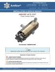
AMFLOW® AM7B Installation & Service Manual INSTALLATION SECTION 2: VALVE INSTALLATION 2.01 INSTALLATION PROCEDURE ADJUSTMENT HANDLE 10 00000015-0301-000 Panel Lock 34 00000122-0301-000 Adjustment Knob 35 00001500-7103-010-00 M3 x 10 SHCS Step 1 Remove ADJUSTMENT KNOB (Item 34) from valve by unscrewing M3 X 10 PHILLIPS SCREW (Item 35) and LOCK-WASHER (Item 33) located in center of ADJUSTMENT KNOB (Item 34). Step 2 Unscrew PANEL LOCK (Item 10) from threaded neck on UPPER BODY (Item 41). Step 3 Insert valve into prepared hole on mounting panel. Step 4 2.02 Replace PANEL LOCK (Item 10) and ADJUSTMENT KNOB (Item 34). INSTALLATION PRECAUTIONS Good system design is critical to the optimum operation of the Amflow® Valves. At a minimum, the design should include: Isolation valves located near inlet and outlet ports of the Amflow® Valve. (The outlet isolation valve is normally a three-way valve that can be incorporated into the calibration loop.) IMPORTANT: The importance of proper media filtering cannot be overstated. It is strongly recommended that filters be placed on both the suction side and the pressure side of pump. It is not unusual to have individual filters inline for each valve. The recommended micron size of the high-pressure filter is somewhat dependent on the specific configuration of any given Amflow® Valve. However, a 50-micron filter size is generally adequate for most applications. The system design should take into consideration that materials which come into contact with the injected media should not contribute to foreign matter entering into the system. This means it is unwise to use material that can be easily corroded, such as mild steels. A check valve located on the outlet side of each Amflow® Valve is strongly recommended. There are a number of reasons for this: The first and most obvious is for safety considerations. The second is to prevent a massive backflow through the Amflow® Valve. This backflow can occur if there is a pump failure or some other system failure that would cause a loss of positive pressure across the Amflow® Valve. The Amflow® Valve is designed to accommodate some backflow conditions; however, piston seal damage can occur if backflow is excessive. The seal is designed to fail under certain conditions in order to prevent damage that is more serious to the valve. END OF SECTION Copyright© 2015 A & H Enterprises, Inc. All rights reserved US PATENTS: 5,427,139 * 5,494,070 * 6,189,564,B1 * EU PATENT 1110132 00000159-0904-000 * Rev. B, 09/15 Page 18 of 43