1
United States Patent [191
[11]
[45]
Peckworth
[54] MILEAGE RECORDING AND SERVICE
REMINDING ACCESSORY FOR A
SHARED-USE VEHICLE
[76] Inventor:
Ralph H. Peckworth, 1241 Rollins
Ave., Charlotte, NC. 28205
[21] Appl. No.: 518,812
[22] Filed:
[51]
Int. Cl.4
[52]
US. Cl. ........................... .. 340/52 D; 235/97
[58]
Field of Search ............. .. 340/52 D, 688; 40/514,
G01D 9/00; B60Q 1/00
40/515; 235/97; 377/82, 87; 70/258, 339, 434
[56]
4,593,263
Jun. 3, 1986
Assistant Examiner-Brian R. Tumm
Attorney, Agent, or Firm-Clifton Ted Hunt
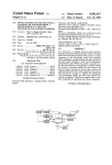
[57]
ABSTRACT
A mileage recording and service reminding accessory
for a shared-use vehicle is provided'as a self-contained
unit which may be installed as original equipment at the
time of manufacture or added as a modi?cation acces
Jul. 29, 1983
.
Patent Number:
Date of Patent:
sory to an existing vehicle. The console includes auxil
iary individual odometers or hour meters for different
persons authorized to use the vehicle, a master meter
within the console, an electric circuit operable to selec
tively connect a desired auxiliary odometer or hour
References Cited
meter to the master meter, and a service warning meter
U.S. PATENT DOCUMENTS
for registering and displaying pre-selected target mile
2,258,525 10/1941
Vigurs ................ ............... .. 40/514
2,435,907
2/ 1948
Schirokauer
. 340/52 D
3,179,336
4/1965
Peckworth
. . . . ..
.. .. . . . .. .
3,856,195 12/1974
3,911,855 10/1975
Kakizaki et a1.
Haven ............ ..
3,925,754
Ota et a1. . . . . .
12/1975
4,159,531 6/1979
4,547,781 10/1985
235/97
.... .. 235/97
340/52 D
. . . .. 340/52 D
McGrath ....... ..
340/52 D X
Gelhorn et a1. ............ .. 235/97 X
ages for prescribed service. The console also includes a
key actuated switch for each of said individual odome
ters or hour meters. Actuation of each switch activates
the ignition and contemporaneously activates only its
respective odometer or hour meter to record the vehi
cle usage for the then current user independently of the
usage recorded for the other users.
Primary Examiner-James L. Rowland
4 Claims, 12 Drawing Figures
(2m
?
6'0
am A 20A Czoc 2'0
('2
l
(25
2'8 ‘[1. gages: EDIE! @
__1’) __ $70
VR)
~ 205
203 El: 0-,’ _7’L.JI’/
m @
E (ii _/_':),_/__:_' 5'4
55 187
a 96
(“P
I 535'
,7 /
I6
/
A / " I/
é/
US. Patent Jun. 3, 1986
Sheet 2 om
4,593,263
’
US. Patent Jun. 3,1986
F194‘
~Sheet3of6
*
FIG.5
4,593,263
_U.S. Patent Jun. 3,1986
¢m
FEE mm»WEN
$8
MnEN5
cm5
_BH J
8m
.vm\ M8
,EN
$113340“
4,593,263
US. Patent Jun. 3,1986
SheetS on
231
4,593,263
US. Patent Jun. 3, 1986'
Sheet6 of6
4,593,263
.r--'-, ---- --* ------ "-1
[CODE F
|SHOP
MILES 30,000
DATE
|
|
|
l
MGR
l
MECHANIC
_
ll iChange engine oil (3,4)
IReplace engine oil' filter ‘(3,4)
IReplace spark plugs (1) (4)
||
r‘ lCheck coolant condition and pro
!tection (5)
{Replace coolant (6)
‘Checking cooling system, hoses,
land clamps (7)
‘Check drive belt condition and tenIsion
iReplace PCV Valve if part number
is specified on engine decal. All
‘others not required (2) (8)
lCheck idle fuel mixture after PCV
|Va1ve replacement if artificial
‘enrichment specifications are
given on engine decal-all others
I "not required. (1) (2)
!
|
Q
|
4
l
'|| 597
l
|
I
l
I
i
i
|
!
|
|
I
|
|
l
|
l_
l
1
4,593,263
2
items called for by the manufacturer’s service manual at
MILEAGE RECORDING AND SERVICE
REMINDING ACCESSORY FOR A SHARED-USE
VEHICLE
each pre-determined mileage interval.
Some of the objects of the invention having been
stated, other objects will appear to those skilled in the
art from the following description when considered in
BACKGROUND OF THE INVENTION
connection with the accompanying drawings wherein:
The use of multi-odometers in a single vehicle to be
BRIEF DESCRIPTION OF THE DRAWINGS
shared by more than one family is disclosed in my prior
US. Pat. No. 3,179,336 issued Apr. 20, 1965 and entitled
MULTI-ODOMETER FOR VEHICLES. That patent
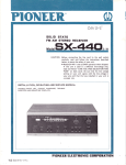
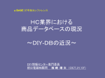
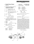
FIG. 1 is a front view of the dash board of a shared
use vehicle equipped with the mileage recording and
service reminding accessory console;
discloses an automatic allocation system dependent on
FIG. 2 is a perspective view of the mileage recording
and service reminding console removed from the vehi
the generation of electrical impulses to allocate mileage
to only the current driver of the vehicle but the system
cle;
disclosed in my earlier patent for controlling the electri
cal impulses proved impractical to install on a vehicle.
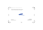
FIG. 3 is a perspective view illustrating the compo
nents of the mileage recording, service reminding, and
service list dispensing features of the console and show
SUMMARY OF THE INVENTION
Unlike my prior patent, all of the mechanism of the
ing the housing in phantom lines;
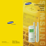
FIG. 4 is a fragmentary perspective view of a read
out wheel containing indicia re?ecting the hours a vehi
present invention is assembled within a single housing
which may be installed as an accessory to a shared-use
cle such as an airplane or boat has operated;
vehicle subsequent to the manufacture of the vehicle.
FIG. 5 is a view similar to FIG. 4 but showing the
A separate odometer is provided for each participant
miles a vehicle such as an automobile has traveled;
in a shared-use vehicle, all of the odometers being
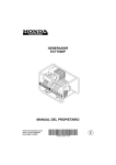
FIG. 6 is a schematic view of the electrical wiring
housed in the console of the accessory package. The 25
diagram connecting the individuals’ speci?c odometers
mileage for each successive driver is recorded not only
within the shared-use console (shown in dashed lines) to
on the odometer with which the car is conventionally
the electrical system of a vehicle and to the electric
equipped at the time of manufacture but also on the
pulse generators operatively connected to the master
speci?c odometer reserved for the driver who is using
meter;
the vehicle at the time the mileage is being recorded.
FIG. 7 is a somewhat schematic view, partially in
perspective and with parts broken away, of a shared
Means are provided for recording the mileage on the
driver’s speci?c odometer by electrical impulses inde
user’s electric odometer, his personal ignition switch,
the pulse generating unit, and the relevant circuitry;
pendently of the conventional cable driven odometer
installed in the car at the time of manufacture.
FIG. 8 is a fragmentary perspective view of a vehicu
Means are also provided in the accessory console for
recording the collective mileage of all users on a pair of
mechanical odometers, one equipped to visually show
total miles, thus serving as a veri?cation unit, and the
lar transmission illustrating attachment of the odometer
cable;
FIG. 9 is an enlarged fragmentary perspective view,
partially broken away for purposes of clarity, of one of
the key-operated lock switches associated with an indi
vidual’s speci?c odometer within the console, as illus
other, herein referred to as the master odometer,
equipped to actuate and control electrical impulses,
both to the personal electric odometers previously men
trated in the wiring diagram of FIG. 6.
tioned, and to a service warning read-out wheel to dis
play a warning when conventional predetermined main
tenance is required on the vehicle, as speci?ed by the
auto manufacturer, either every 7,500, 10,000 or 15,000
miles.
It is an object of the invention to provide an acces
FIG. 10 is a somewhat schematic side elevation of the
gearing associated with the service reminding meter;
45
FIG. 11 is a front view of the service reminding meter
and the gearing shown in FIG. 10; and
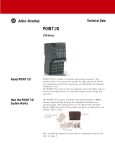
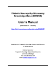
FIG. 12 is a plan view of a clip board which may be
conveniently stored in the vehicle and used to perma
sory for a shared-use vehicle of the type described
nently record the servicing performed on the vehicle in
wherein all elements of the invention are contained
accordance with the service reminder meter.
within a single console and wherein the console is 50
DETAILED DESCRIPTION OF THE
equipped with ports for connection to the transmission
INVENTION
and to the electrical system of the vehicle.
It is another object of the invention to provide a
Referring more speci?cally to the drawings, the nu
mileage allocation recording system and service re
meral 10 broadly indicates a shared-use console adapted
minding system for a shared-use vehicle of the type
to be mounted beneath the dashboard 11 of a vehicle,
described and wherein the system includes means for
not shown. The vehicle may be an automobile, a trac
generating and controlling electrical impulses to record
tor, an airplane, or a boat, for example. It is conven
the mileage within the accessory console to only the
tional for an automobile to use an odometer 20 (FIG. 5)
current driver of the vehicle.
to record the mileage traveled by the automobile, and it
It is a further object of the invention to provide a
is conventional to use an hour meter 201 (FIG. 4) to
service reminder for a vehicle comprising means for
record the hours of operation of other vehicles, such as
recording the mileage of the vehicle and making it re
sponsive to the generation of electrical impulses and
airplanes and boats. The invention is equally useful with
an odometer or with an hour meter, and the illustrated
embodiment is described as being used with an odome
is due in black ?gures, and subsequently showing the 65 ter for purposes of illustration.
means for posting the next target mileage when service
target mileage in red when the service is actually due.
The console 10 includes a front wall 12, side walls 13,
It is a further object of the invention to provide
means for dispensing a pre-printed listing of the service
14, a top wall 15 and a bottom wall 16. The front wall
12 includes a plurality of read-out windows through
3
4,593,263
4
which the displayed numbers of the shared-user’s spe
personal circuit and meter when surrendering the vehi
ci?c odometer and the service reminder odometer can
cle to another user. These are the only occasions when
use of his personal key is required. All other stops and
be read. Read-out windows A, B, C and D display, for
starts only require use of the conventional ignition key
example, respective odometers 20A, 20B, 20C and 20D
of personnel sharing the use of the vehicle and hereafter 5 in the normal manner.
referred to in an explanatory manner as Abbott, Brown,
Collins and Dolan. The console 10 also includes locks
21A, 21B, 21C, and 21D co-operatively associated with
respective odometers 20A, 20B, 20C and 20D and ac—
cessible through the front wall 12 of the console. The
locks are responsive to actuation by respective differing
keys owned by the users of the vehicle, Abbott, Brown,
Collins and Dolan to actuate their respective odometers
only when any one of them is using the vehicle. A sec
ond key or keys, available to all of the users, ?ts the
standard or conventional ignition 22 of the vehicle,
located in a conventional manner either on the dash
ELECTRICAL STARTER CIRCUIT
Referring to FIG. 6, the electrical starter circuit can
be traced from a battery 30 through an electrical con
ductor or wire 31, through wiring port 100 and Battery
Bus Bar 31‘, thence through a selected one of the lock
switches 21A, 21B, 21C or 21D which has been closed
to make connection with another electrical conductor
or wire 32 leading through an Ignition Bus Bar 321 and
the wiring port 100 to one terminal of the conventional
ignition-starter switch 22, and across the switch 22
when closed to the other terminal thereof. Another
board or the steering post.
conventional electrical conductor or wire 33 extends
from said other terminal of the switch 22 to the starter
ated by unlocking the ignition which momentarily 20 mechanism 34.
closes a starter switch wired in series with the starter
The lock switches 21A, 21B, 21C and 21D are wired
in parallel across the electrical conductors 31 and 32.
mechanism and a battery providing the source of elec
Thus, the electrical starter circuit can only be com
tric energy. In the present instance, the wiring diagram
pleted by closing the conventional ignition switch 22
of FIG. 6 schematically shows the ignition switch 22 as
a push-button switch for purposes of simplicity, 25 after any selected one of the lock switches 21A, 21B,
21C or 21D has been closed to position plate 25 across
wherein it is assumed that the ignition switch has been
Normally, the starter mechanism for a vehicle is actu
closed and the push~button switch 22 represents the
starter switch of the vehicle with the ignition switch
already closed. It should be understood that the switch
22 shown in the wiring diagram of FIG. 6 is for illustra 30
spaced apart terminals linking the electrical conductors
31 and 32. Closing one of the above lock switches 21A,
21B, 21C or 21D also positions plate 26 across spaced
apart terminals linking the per mile impulses from
switch 42 to one of the properly allocated personal
.tive purposes only, as the conventional type of com
bined ignition-starter switch now found on most vehi
mileage recorders, 20A, 20B, 20C or 20D by closing the
cles is intended to be schematically represented by the
terminals connecting bus bar 52 to connector wire 54.
switch 22 in FIG. 6. As is well known, the conventional
OTHER PURPOSES OF A SHARED~USE
VEHICLE
The console 10 may also include odometers and lock
switches to be activated by appropriate keys for other
..quent continued manual turning of the rotatable cylin
purposes of the shared-use vehicle. Thus, lock switch
der in the same direction to close the starter switch for
1: actuating the starter mechanism to begin the operation 40 21R and its corresponding odometer 20R may be acti
vated by an appropriate speci?c key when manipulated
of the internal combustion engine. When manually re
by one who has rented the vehicle from the owners.
leased, the rotatable cylinder of the ignition-starter
Provision may also be made for the shared-use vehicle
switch 22 turns in the opposite or counter-clockwise
direction to the “on” position of the ignition switch
to be operated as a pool vehicle. In this instance, it is
while opening the starter switch in the well-known 45 contemplated that it will take two speci?c keys to oper
ate two speci?c lock switches 21F and ZIP1 to activate
manner.
the starter mechanism in addition to the conventional
According to the present invention, the closing of the
ignition switch so that there can be veri?cation that the
starter switch of the combined ignition-starter switch 22
in the manner described will not actuate the starter
pool car was used as intended, and the pool mileage
mechanism to start the internal combustion engine‘or 50 registered on odometer 20?. Thus, a rural residing fac
maintain the ignition actuation unless one of the inde
tory worker with a high mileage commute, who would
normally not be accepted by a small town group com
pendently operable shared-use locks 21A, 21B, 21C or
muting to the city, can join such an out of balanced “car
21D has been rendered operable by inserting the spe
pool” since his excess rural mileage can be recorded
ci?c key for that lock and turning its rotatable cylinder
23 (FIG. 9). The rotatable cylinder 23 contains an elon 55 separately from the car pool mileage without recourse
to any bothersome record keeping.
gate spindle 24 movable therewith and on which are
Another feature of this invention that will encourage
carried a pair of spaced switch plates 25, 26 having
the use of car pools, is the fact that a group such as
switch contacts at their opposite ends. Thus, activation
of a shared-use lock, such as 21A, enables operation of
Abbott, Brown, Collins and Dolan can use the vehicle
the ignition system and at the same time activates the
on week days for commuting to work, and take turns
corresponding odometer 20A, for example, to register
using the same vehicle for recreational purposes on
ignition-starter switch is provided with a rotatable cyl 35
inder which may be manually turned with or without
the use of a key to unlock the ignition, permitting subse
the mileage of the key-holding current driver, Abbott.
It should be noted that the personal keys carried by
Abbott, Brown, Collins and Dolan are removable in
both the “on" or “off’ positions and that it is necessary 65
for each individual operator to use his personal key only
to activate the ignition circuit and his personal meter
when taking over the vehicle and again to deactivate his
weekends, evenings, or other “non-work” time periods.
ILLUSTRATIVE USE OF THE SHARED-USE
SYSTEM
Assuming that a participant in the shared-use vehicle,
Abbott, desires to use the vehicle and has started the
engine by placing his speci?c key in lock switch 21A
5
4,593,263
and has placed the general use ignition key in ignition
switch 22 and thereby started the engine, the mileage
6
counter wheel of odometer 40 in spaced relation from
the housing 43 but is moved inwardly toward the hous
ing to depress the button 44 upon engagement with the
traveled by the shared-use vehicle will then be recorded
on the odometer 35 (FIG. 1) conventionally installed
shoulder 41, once per mile or each time the counter
adjacent the speedometer on the dashboard of the vehi 5 wheel 40 makes a complete revolution.
cle. The mileage is recorded on the conventional odom
A pair of electric conductors or wires 50 and 51 ex
eter 35 by a conventional speedometer cable 36 extend
tend from the switch 42, the wire 50 being connected to
ing from the transmission T of the vehicle (FIG. 8).
a battery bus bar within the console and thence through
Additionally, the mileage traveled by the vehicle
the wiring port to battery 30, and the wire 51 being
while being operated by Abbott will be recorded on his
connected to a bus bar 52 within the console 10; and
hence to terminals at switch plate 26 of lock switch
21A. With Abbot’s key inserted in lock switch 21A and
assigned odometer 20A and on a veri?cation odometer
351 (FIGS. 1 and 2) through a separate cable 37 (FIG. 8)
extending from the transmission T through a dual cable
adapter 38. The transmission cable 37 extends to the
cable port 101 in the console 10 (FIGS. 3 and 6) where
it is secured by a conventional speedometer type cable
head to gearing 39 and hence the veri?cation odometer
the cylinder in that look rotated to energize the ignition
switch 22 to start the vehicle, the closing of the termi
nals 25 and 26 in lock switch 21A simultaneously estab
lishes a circuit between the switch 42 and the odometer
20A to record Abbott’s mileage. Each of the odometers
20A through 20P within the console 10 is a conven
tional electric odometer having the odometer unit and
the actuating mechanism housed together in a unit cas
ing in a conventional manner, with external terminals
351 and also to master odometer 40.
TYPES OF ODOMETERS
The conventional odometer 35, the master odometer
40 and a veri?cation odometer 351 are all mechanically
driven and the ?rst right hand wheel of each is a unit
wheel arranged to register “tenths” of a mile. These
541, 551 (FIG. 7) which renders the odometer respon
sive to electrical impulses from switch 42 after each
revolution of the right hand (or demical wheel) of mas
odometers operate constantly whenever the vehicle is 25 ter odometer 40. Wires 54 extend from the electric
odometers to the terminals of switch plate 26 inside key
switch 21A (FIG. 9) which, when closed, connects to
20R are selectively operated electric odometers having
bus bar 52 and wire 51 to connect the electric odometer
in operation.
The individual odometers 20A, 20B, 20C, 20D, 20P,
the counter wheels and the actuating solenoid mecha
20A to the electric pulse switch 42. Wire 55 from each
nism enclosed together in a conventional manner in a 30 electric odometer connects, via ground bus bar 551,
unit housing. The ?rst right hand wheel of each is a
“units” wheel registering one mile for each number
segment or 10 miles per revolution. Both the mechani
through wire port 100, to an outside ground. Each time
a pulse is generated by engagement of the abutment 41
with the follower 46, an arm 56 projects from the sole
noid 53 to engage a ratchet wheel 57 and impart an
cal and the electric odometers comprise a plurality of
counter wheels journaled on a commonv shaft and 35 increment of rotation to the right hand wheel. The
mounted for segmental rotation in a conventional man
ratchet wheel 57 is journaled with the counter wheels
ner common to counters or odometers.
on the odometer 20A so that rotation of the ratchet
Veri?cation odometer 351 is readable through a read
out window and may be used as veri?cation of the total
wheel causes corresponding rotation of the right hand
units wheel. The decimal wheel of master odometer 40
miles by comparison with the conventional odometer 35 40 makes a complete revolution once per mile and each
on the vehicle’s instrument panel, thereby con?rming
time the abutment 41 moves the follower 46 against the
that the console has been connected at all times. Each
button 44, a pulse is generated to activate the electric
wheel is numbered from zero to nine around its circum
odometer and impart one tenth rotation or one numeral
ference and, as is conventional, the right hand wheel
advance to the unit wheel and signify passage of one
rotates to present a new numeral at the viewing window 45 miles.
for every tenth of a mile of operation. A complete revo
The example given for Abbott and his odometer 20A
and lock 21A is equally applicable to the other locks
lution of the right hand wheel imparts movement of
one-tenth of a revolution to the next wheel as is conven
tional.
THE MILEAGE ALLOCATION SYSTEM
and odometers within the console 10. The invention can
be adapted for use with an hour meter 201 by substitut
50 ing a conventional electric clock driven mechanism for
the speedometer cable 37 and the gearing 39, and using
The master odometer 40 differs from the conven
tional odometer and the other odometers in the console
of this invention by including means to convert certain
digit wheels into rotary switches to sense a complete 55
The standard ignition key supplied by the vehicle’s
revolution of the wheel. In the illustrated embodiment,
a shoulder or abutment 41 extends axially along the _
surface of the right hand wheel at the portion of the
circumference coinciding with the location of the nu
meral zero.
The shoulder 41 on the right hand wheel extends into
the path of an electrical switch broadly indicated at 42
and comprising a housing 43 (see FIG. 6) containing
it to drive a set of dual hour meters', one to serve for
veri?cation and the other as a master clock unit serving
as rotary switches to generate impulses in the same
manner as that described for the master odometer.
manufacturer, and carried in a special keycase, with the
trunk key, and a special credit card, stays with the vehi
cle at all times, being passed from one user to the other.
60 This key is the only key necessary for all routine stops
and starts, in the same manner as if the user were the
sole owner.
THE SERVICE WARNING SYSTEM
terminals, not shown, which are closed to complete a
circuit upon depression of a button 44 caused by inward 65
The master odometer 40 has no read-out window
movement of a pivoted arm 45 resulting from impinge
since its main purpose is to control electrical impulses
ment of a follower wheel 46 with shoulder 41. The
originating within the console, both to record allocated
follower wheel 46 rests on the circumference of the
mileage, as previously described, and to give warning of
7
4,593,263
the approach and the arrival of various pre-determined
8
scribed as follows with reference to FIG. 6:
SPECIFYING SERVICE REQUIREMENTS
Code letters D through H listed with the target mile
age FIG. 91 displayed through window 87 coincide
The Service Warning System is included in the con
sole 10 and responds to electrical impulses controlled, in
with a corresponding code letter on a plasticized pre
printed paper tape 70 (FIG. 3) wound on a shaft 93
target mileages at which service work on the vehicle is
recommended. This service warning system is de»
suitably journaled within the console 10. The tape 70 is
the case illustrated by the left hand or “hundreds”
wheel 60 of the master total miles odometer 40. The
printed with the code letters and servicing to be per
formed at each targeted mileage. The tape 70 rolled up
on shaft 93, unwinds over a slanting plate 94 which
“hundreds” wheel has a shoulder or abutment 61 at the
“zero” position, and a diametrically opposed shoulder
guides the tape to a dispensing slot 95 in the face of the
console 10. A pivoted door 96 normally covers the slot
or abutment 62 at the “5” position.
A switch 63 is mounted within the console 10 adja
95, and the protruding tape 97 remaining after each
cent the “hundreds” wheel 60 of the master odometer
“tear off" is con?ned and concealed by closing the door
40. The switch 63 is similar to the previously described
switch 42 and includes a pivoted arm 64 equipped with - 5 96 on it so that prongs (not shown) on the under side of
the door pierce and hold the tape against retraction.
a follower wheel 65 resting on the circumference of the
hundreds wheel and engageable by the shoulders 61 and
Suitable conventional braking devices (not shown) im
pinge on the shaft 93 and the length of tape 70 over the
62 as the hundreds wheel rotates. Engagement of the
slanting plate 94 to avoid premature unwinding or loos
follower wheel 65 with one of the shoulders 61 or 62
closes contacts, not shown, within the switch 63 to 20 ening of the preprinted tape 70.
When the service work indicated by the displayed
generate a pulse every 500 miles which is sent through
code letter is to be performed, the vehicle is delivered to
wire 67 to solenoid 81 (FIGS. 3 and 6). Wire 68 con
the service department. The driver raises the pivoted
nects switch 63 to battery bus bar 311. Thus rotation of
door 96 and graps the end of the preprinted plasticized
wheel 60 actuates the switch 63 twice per revolution or
every 500 miles. The unseen terminals of the switch are 25 paper tape 70 protruding from the slot 95 and pulls the
tape out until a tear-off point marked on the tape
closed to complete a circuit upon depression of a button
reaches the bottom of door 96. By closing the door
66 caused by inward movement of the pivot arm 64
resulting from impingement of the follower wheel 65
(which has abrasive teeth on the under side) on the tape
the driver can tear off the relevant portion of the tape
with shoulders 61 and 62.
bearing the listing of the work speci?ed under the dis
Each pulse generated by the switch 63 actuates the
played code letter for the current target mileage.
solenoid 81 to move a thirty-cog ratchet wheel 82
(FIGS. 6 and 10) one ratchet cog, or 12° every 500
The driver places the tom-off tape portion bearing
miles, completing one revolution every 15,000 miles.
the list of current service requirements on a small clip
Attached to the ratchet wheel 82 is a gear blank 83 of
board 97 (FIG. 12) stored in retaining clips under the
slightly lesser diameter having gear tooth segments
83A, 83B, 83C, and 83D at the quarter points which
35 console 10 and leaves it with the attendant or mechanic.
engage in a conventional manner the pinion gear 84
which the torn-off tape 70 is placed. The portion of the
(FIGS. 10 and 11) that transfers rotation in 12° incre
tape 70 protruding beyond the right edge of the plastic
ments to a sixty-tooth gear 85 (FIG. 11) af?xed to a
large read-out wheel 86 inscribed on its circumference
cover 98 permits the mechanic to check off the work
with the manufacturer’s designated target mileages for
pre-determined service. The inscribed target mileages
are sequentially visible through service warning win
dow 87 (FIGS. 3 and 11).
of the tape. Dated and signed, this list serves as a good
record of the service work on the vehicle, enhancing its
The ratchet wheel 82 makes one revolution every 45
The clip board 97 has a clear plastic cover 98 under
items as performed without soiling the printed portion
resale value, but more importantly insuring the sharing
users that the vehicle is safely maintained.
This provision of the service reminder is particularly
15,000 miles (30 cogs><500 miles) and its rotation is
advantageous in a shared-use vehicle because it enables
transferred four times per revolution of shaft S in FIGS.
10 and 11 by the four sets of gear segments, 83A, 83B,
83C and 83D located at quarter points of gear segment
maintain the vehicle in good condition without having
83, thus advancing the service reminder read-out wheel
86 every 3,750 miles. The ?rst showing of successive
all users to know when service is desired in order to
to keep independent notes or consult with the other
users of the vehicle.
target mileage ?gures, beginning with the target mile
SUMMARY OF THE INVENTION
age ?gure of 7,500, appear in black (as at 90 in FIG. 11)
through the window 87 after the vehicle has traveled
There is thus provided an improved mileage alloca
tion recording system and a service reminding system
3,750 miles and serves to warn all operators of the ser
which are self-contained in a console capable of being
vice scheduled to be performed after the vehicle has
traveled 7,500 miles. The next showing of the same
7,500 mile target ?gure will appear in red as at 91 in
FIG. 11 when the vehicle has traveled 7,500 miles and
share use of the vehicle with other personnel thereby
decreasing the operating expense to each user.
The expense of operation may be equitably appor
the scheduled service is due. In like manner, the suc
ceeding target mileages are shown on the read-out
wheel 86, ?rst in black as at 90 to announce the next
pending target mileage, and then in red as at 91 to indi
cate when the service is due. The nature of the service
added as an accessory to a vehicle after it is decided to
tioned among the users depending upon their actual use
of the vehicle as determined by the mileage recorded on
the individual’s odometer within the console. All users
are relieved of the responsibility of keeping records as
to the necessary maintenance for the vehicle by the
scheduled for each target mileage is represented by a 65 service reminder which dispenses written instructions
code letter printed on the circumference of the read-out
wheel 86 beside the red numerals and illustrated as D
when service is due on the vehicle.
through H in FIG. 11.
of a vehicle the normal monthly lease payment can be
By further facilitating the prospect of group leasing
4,593,263
reduced to approximately one-fourth (i) of the normal
10
of the group of auxiliary odometers and of the addi
tional car pool odometer enables the breakdown of
lease payment in the case of a four party agreement.
The invention will also facilitate the use of a common
commuting trips into private and car pool portions.
vehicle in different types of usage, for example, four
2. An accessory for a shared use vehicle having a
workers can acquire a passenger van for use in a “go to 5 meter responsive to cumulative use of the vehicle and
work” van pool, arrange for rental of the van to their
also having a group of auxiliary meters, each auxiliary
meter being selectively operable to register only the use
of the vehicle by a speci?c user, the above meters being
employer for delivery service between 10 A.M. and 4
P.M., and for their own personal recreational weekend
use once a month.
combined with an additional meter for car pool use,
means requiring a plurality of users to activate the said
additional meter for car pool use, and means for inform
Although specific terms have been employed in de
scribing the invention, they are used in a descriptive
sense only and are not intended as limitation, since the
invention may also be used to minimize both the leasing
ing the then current user that the said target mileage has
been reached and that the said scheduled maintenance is
and operating expense of boats, planes, tractors, and
other vehicles.
I claim:
15
actually due.
1. A shared-use vehicle having a master meter re
sponsive to cumulative use of the vehicle and also hav
3. A structure according to claim 2 which also in
cludes means for warning all users of the pending target
mileage when the next scheduled maintenance of the
ing a group of auxiliary meters each of which is selec
the vehicle will be due.
tively operable to register only the use of the vehicle by 20
a speci?c person, said shared-use vehicle including an
additional electric odometer controlled by two switches
in series with each other and with the said additional
odometer, whereby the combined use of selected ones
'
4. A structure according to claim 3 which also in
cludes means for presenting to the then current user a
printed list of the service work recommended for the
scheduled maintenance that is then due.
*
25
35
45
50
55
65
1k
*
it
*