1
Back
Installation Manual
Electronic Chart Display and
Information System (ECDIS)
FEA-2107/2107-BB/2107-D
FEA-2807/2807-D
SAFETY INSTRUCTIONS...................................................................................... i
EQUIPMENT LIST................................................................................................. ii
SYSTEM CONFIGURATIONS ............................................................................. iv
1. MOUNTING ................................................................................................... 1-1
1.1
1.2
1.3
1.4
Monitor Unit ................................................................................................................. 1-1
Control Unit ................................................................................................................. 1-5
Processor Unit........................................................................................................... 1-10
LAN Adapter/B Adapter ..............................................................................................1-11
2. WIRING.......................................................................................................... 2-1
2.1
2.2
2.3
2.4
2.5
2.6
2.7
2.8
2.9
Wiring .......................................................................................................................... 2-1
Processor Unit............................................................................................................. 2-5
LAN Adapter ................................................................................................................ 2-7
B Adapter (EC-1000C-C-S/EC-1000C-CR only) ....................................................... 2-13
Radar Overlay (EC-1000C-R/EC-1000C-CR only).................................................... 2-19
Connection of Digitizer and LCD Displays to Processor Unit .................................... 2-20
Power Cabling to ECDIS ........................................................................................... 2-20
Ethernet Cable Connection ....................................................................................... 2-21
EMI Core for Processor Unit ..................................................................................... 2-22
3. ADJUSTMENTS ............................................................................................ 3-1
3.1
3.2
3.3
3.4
3.5
3.6
3.7
How to Set IP Address for ECDIS ............................................................................... 3-1
Parameters .................................................................................................................. 3-3
Adjustments for the Second LAN Adapter EC-1010.................................................. 3-64
DIP Switches and Jumper Wires ............................................................................... 3-71
Installation of Optional Furuno PP-510 Printer .......................................................... 3-76
Activation of CM-93/3 ................................................................................................ 3-82
Reinstall of ECDIS Software...................................................................................... 3-87
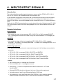
4. INPUT/OUTPUT SIGNALS ........................................................................... 4-1
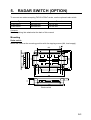
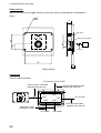
5. RADAR SWITCH (OPTIONS) ....................................................................... 5-1
PACKING LISTS ............................................................................................... A-1
OUTLINE DRAWINGS ...................................................................................... D-1
INTERCONNECTION DIAGRAM ......................................................................S-1
www.furuno.co.jp
All brand and product names are trademarks, registered trademarks or service marks of their respective holders.
The paper used in this manual
is elemental chlorine free.
・FURUNO Authorized Distributor/Dealer
9-52 Ashihara-cho,
Nishinomiya, 662-8580, JAPAN
Telephone : +81-(0)798-65-2111
Fax
: +81-(0)798-65-4200
All rights reserved.
Printed in Japan
A : SEP . 2004
J : MAR . 10, 2011
Pub. No. IME-41220-J
(HIMA )
FEA-2107/BB/2807
*00014977518*
*00014977518*
* 0 0 0 1 4 9 7 7 5 1 8 *
SAFETY INSTRUCTIONS
WARNING
WARNING
Do not open the equipment
unless totally familiar with
electrical circuits and
service manual.
ELECTRICAL
SHOCK
HAZARD
The PCI-951/PCG820 board is equipped
with a litium battery. The lithium battery
shouldbe replaced only in the factory.
There is a danger of explosion if the wrong
type of battery is used for replacement.
Only qualified personnel
should work inside the
equipment.
CAUTION
Turn off the power at the mains switchboard before beginning the installation.
Attach securely protection
earth to the ship's body.
Fire, electrical shock or serious injury can
result if the power is left on or is applied
while the equipment is being installed.
The protection earth
(grounding) is required to the
AC power supply to prevent
electrical shock.
Do not install the monitor unit, processor
unit or control unit where they may get
wet from rain or water splash.
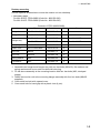
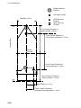
Observe the following compass safe
distances to prevent deviation of a
magnetic compass:
Water in the units can result in fire, electrical
shock, or damage the equipment.
Standard
compass
Be sure that the power supply is
compatible with the voltage rating of
the equipment.
Connection of an incorrect power supply
can cause fire or damage the equipment .
Use only the specified power cable.
Fire or damage to the equipment can result
if a different cable is used.
Processor
Unit (EC-1000C)
1.65 m
1.05 m
LAN Adapter
(EC-1010)
1.05 m
0.70 m
B Adapter
(EC-1020)
0.80 m
0.50 m
Control Unit
(RCU-018)
0.30 m
0.30 m
0.95 m
0.60 m
0.65 m
0.45 m
2.25 m
1.40 m
2.55 m
1.55 m
1.65 m
1.05 m
0.85 m
0.55 m
1.00 m
0.60 m
Control Unit
(RCU-015)
Control Unit
(RCU-016)
Monitor Unit
(MU-201CE-DV15)
Monitor Unit
(MU-231CE-DV15)
Monitor Unit
(MU-190)
Monitor Unit
(MU-231)
Switching HUB
(HUB-100)
i
Steering
compass
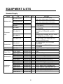
EQUIPMENT LISTS
Standard Supply
Name
Monitor Unit
Processor
Unit
Type
Code No.
Qty
MU-201CE-DVI5
-
MU-231CE-DV15
-
MU-190
MU-231
-
EC-1000C
-
EC-1000C-R
-
EC-1000C-C
-
EC-1000C-CR
-
RCU-018-E
-
1
RCU-015FEA-E
-
1
000-083-570
008-549-730
000-087-221
008-536-010
008-535-610
008-535-690
000-082-651
000-087-219
008-539-850
000-083-624
000-083-501
000-083-502
000-083-507
000-083-508
1
1
1
1
1
1
1
1
1
1
1
1
1
1
1
1
1
1
Control Unit
LAN Adapter
B Adapter
Spare Parts
Accessories
Installation
Materials
EC-1010
EC-1020
SP03-14800
SP03-14700
FP03-10700
FP03-09810
FP03-09850
FP03-09860
CP03-29020
CP03-29100
CP03-25604
CP03-29110
CP03-29500
CP03-29510
CP03-29600
CP03-29610
ii
Remarks
For FEA-2107, w/DVI cable (5 m),
SP03-14700, CP03-29020, FP03-09810
For For-2807, w/DVI cable (5 m),
SP03-14700, CP03-29020, FP03-09810
For FEA-2107-D
For FEA-2807-D
Standard type: Processor unit (EC-1000C
w/S-DONGLE)
Radar Overlay type: Processor unit
(EC1000C w/ S-DONGLE and ROV
board)
Conning type: Processor unit (EC-1000C,
w/S-DONGLE and VIDEO board)
Conning/Radar Overlay type: Processor
unit (EC-1000C, w/S-DONGLE, ROV
board and VIDEO board)
Full keyboard type, w/CP03-25604,
FP03-09850
Trackball type, w/CP03-25604,
FP03-09860
For EC-1000C-C and EC-1000C-CR
Fuses
Fuses, for AC spec.
For processor unit
For Monitor unit
For Control unit RCU-018-E
For Control unit RCU-015FEA-E
For Monitor unit
For EC-1000C-R Processor unit
For Control unit RCU-015/018-E
For EC-1000C-C/CR Processor unit
For EC-1000C/C-R, D-SUB cable 5 m
For EC-1000C/C-R, D-SUB cable 10 m
For EC-1000C-C/CR, D-SUB 5 m
For EC-1000C-C/CR, D-SUB 10 m
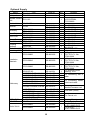
Optional Supply
Name
LAN Adapter
B Adapter
Type
EC-1010
EC-1020
Remote Control
RCU-016
Unit
Monitor Unit
MU-201CE
Rectifier
PR-62
Accessory
Hand Grip
Dust Cover
Clamp Plate
Flush Mount Kit
Coupling
Pedestal
Flush Mount Kit
Switching HUB
Installation
Materials
Cable assy
VIDEO PCB
ROV PCB
Code No.
-
Qty
1
1
-
1
FP03-09820
FP03-09830
FP03-09840
03-163-1201
03-163-2101
OP03-182
FP03-09870
OP03-183
000-013-484
000-013-487
008-535-560
008-536-020
008-535-570
100-307-260
100-307-270
008-535-620
008-535-630
008-535-640
1
1
1
1
1
1
1
1
1
1
1
OP03-184
008-535-650
1
FP03-09870
HUB-100
008-535-630
000-083-353
1
1
CP03-28900
000-082-658
1
CP03-28910
000-082-659
1
CP03-28920
000-082-660
1
3COX-2P-6C
000-146-501
1
NH8P-DSUB15BNC2-10M
NH8P-DSUB15BNC2-20M
NH8P-DSUB15BNC2-30M
XH8P-NH8P-L10M
XH8P-NH8P-L20M
XH8P-NH8P-L30M
000-151-857
000-151-858
000-151-859
000-151-855
000-151-933
000-151-934
1
1
1
1
1
1
DSUB9P-DSUB9P-L10.0M 000-150-676
1
MOD-Z072-100+
MOD-Z072-020+
XH10P-DS-5P L=2.3M
XH10P-DS-5P L=20M
XH10P-DS-5P L=30M
G45FMDVP32DBF
301074
000-167-177-10
000-167-175-10
000-150-001
000-149-745
000-149-746
1
1
1
1
1
1
1
CP03-29501
008-544-940
000-165-667-10
000-150-680
Radar Switch
1
CP03-29502
008-544-950
iii
Remarks
Remote type,
w/CP03-25604,
FP03-09860
For 100 VAC
For 230 VAC
For MU-201CE, hanger
For MU-231CE, hanger
For MU-201CE
For MU-231CE
For RCU-018
For RCU-018
For RCU-018
For RCU-018 and
MU-231CE
For RCU-015FEA
w/operator’s manual
LAN cable
FR-FTPC-CY 10m,
CP03-28901
LAN cable
FR-FTPC-CY 20m,
CP03-28901
LAN cable
FR-FTPC-CY 30m,
CP03-28901
For external monitor
(analog), 10 m
For connecting with a
radar
For connecting Radar
switch and radar
Between
Monitor/Processor unit
LAN cable (cross)
For Control unit
Conning Board
Radar Overlay Board
For 12 VDC,
for EC-1000C-R/CR
For 24 VDC,
for EC-1000C-R/CR
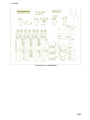
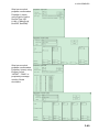
SYSTEM CONFIGURATIONS
The ECDIS EC1000 Workstation displays electronic seachart and operates as user
interface for the system. The ECDIS processor is connected to various sensors, and
performs navigation calculations and route monitoring. Connections to interfaces are
typically made with a LAN (Local Area Network) Adapter. The ECDIS processor can be
used for both route planning and route monitoring. If required, there can be additional
identical ECDIS EC1000C Workstation(s) connected to the same LAN to share the tasks of
the ECDIS. If the system incorporates more than one ECDIS EC1000C Workstation, one or
more workstation(s) can be used as a user interface (with “full” usage rights) and one or
more workstation(s) may be used as planning stations (usage rights as “planning”). If the
system has two or more Workstations connected together as multi-workstations, the system
keeps data on the workstations harmonised and also tracks selections and settings made
on any workstation.
Typically there can be the following kinds of workstation configuration:
Mode as Single, only one workstation is used in the system.
Mode as Multi, two or more workstations are used in the system where usage rights and
sensor source of workstations can be changed by the user.
For more information, see the operator’s manual.
One workstation
100-230 VAC
ECDIS Monitor
Conning Monitor
MU-201CE (FEA-2107)
MU-190 (FEA-2107-D)
MU-231CE (FEA-2807)
MU-231 (FEA-2807-D)
MU-201CE (FEA-2107)
MU-190 (FEA-2107-D)
MU-231CE (FEA-2807)
MU-231 (FEA-2807-D)
100-230 VAC
LAN ADAPTER
EC-1010
Rectifier
PR-62
24 VDC
DVI or RGB
ARPA RADARS
POSITION-FIXING EQUIPMENT
TRACK PILOT
LOG/DUAL AXIS LOG
AIS
GYRO COMPASS
DVI or RGB
CALCOMP
DRAWINGBOARD III
DIGITIZER
100/230 VAC
HUB100
LAN ADAPTER
EC-1010
(WORKSTATION)
FAR-2xx7 series
ECDIS PROCESSOR
EC1000C
100-230 VAC
100-230 VAC
24 VDC
Rectifier
PR-62
100/230 VAC
RADAR OVERLAY PCB
B ADAPTER
EC-1020
Control Unit
RCU-018
or
TB Control Unit
RCU-015FEA
24 VDC
POSITION-FIXING EQUIPMENT
ENGINE CONTROL
ECHOSOUNDE R
WIND SENSOR
WATER TEMP. METER
AMWSS (Alarm Monitoring
Watch Safety System)
GYRO COMPASS
(SYNCHRO, STEPPER)
LOG (200P/NM)
ANALOG INPUT (8 CHANNELS)
ALARM OUTPUT (8 CHANNEL)
Rectifier
PR-62
100/230 VAC
RADAR
SWITCH
Remote Control Unit
RCU-016
RADAR 1 (VIDEO, HL , AZ)
RADAR 2 (VIDEO, HL , AZ)
PRINTER
(USB)
ALARM OUTPUT
(ECDIS SYSTEM FAIL)
OPTION
EXTERNAL
DEVICE
iv
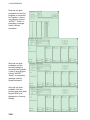
Multi-workstation configuration
In the multiple workstation configuration, there can be two workstations connected together
by a Local Area Network (LAN). In this configuration, one workstation is used as the “sensor
source” for navigation sensors and the other workstation(s) are using the sensor source
workstation to communicate with sensors, receiving and transmitting data from/to
workstation via the LAN. In the multi-workstation configuration (two fully redundant
navigation workstations), where navigation sensors are connected to two workstations, the
sensor source may be changed and still receive and transmit information from/to the system
and to/from navigation sensors. User-defined workstation is responsible for sensors.
ECDIS Monitor
100-230 VAC
Conning Monitor
MU-201CE (FEA-2107)
MU-190 (FEA-2107-D)
MU-231CE (FEA-2807)
MU-231 (FEA-2807-D)
MU-201CE (FEA-2107)
MU-190 (FEA-2107-D)
MU-231CE (FEA-2807)
MU-231 (FEA-2807-D)
ARPA RADARS
POSITION-FIXING EQUIPMENT
TRACK PILOT
LOG/DUAL AXIS LOG
AIS
GYRO COMPASS
100-230 VAC
LAN-ADAPTER
EC-1010
DVI or RGB
Rectifier
PR-62
DVI or RGB
24 VDC
POSITION EQUIPMENT
ENGINE CONTROL
ECHOSOUNDER
WIND SENSOR
WATER TEMP. METER
AMWSS (Alarm Monitoring
Watch Safety System)
100/230 VAC
CALCOMP
DRAWING BOARD III
DIGITIZER
HUB100
LAN-ADAPTER
EC-1010
(WORKSTATION)
ECDIS PROCESSOR
EC1000C
100-230 VAC
24 VDC
Rectifier
PR-62
GYRO COMPASS
(SYNCHRO, STEPPER)
LOG (200P/NM)
ANALOG INPUT (8 CHANNELS)
ANALOG OUTPUT (ECDIS, 8 CHANNEL)
100/230 VAC
B-ADAPTER
EC-1020
RADAR OVERLAY PCB
100-230 VAC
Rectifier
PR-62
24 VDC
Control Head
RCU-018
or
TB Control Unit
RCU-015FEA
ALARM OUTPUT
(ECDIS SYSTEM FAIL)
100/230 VAC
RADAR
SWITCH
RADAR 1 (VIDEO, HL, AZ)
RADAR 2 (VIDEO, HL, AZ)
PRINTER
(USB)
Remote Control Unit
RCU-016
ECDIS Monitor
100-230 VAC
MU-201CE (FEA-2107)
MU-190 (FEA-2107-D)
MU-231CE (FEA-2807)
MU-231 (FEA-2807-D)
ARPA RADARS
POSITION-FIXING EQUIPMENT
TRACK PILOT
LOG/DUAL AXIS LOG
AIS
GYRO COMPASS
LAN ADAPTER
EC-1010
Rectifier
PR-62
24 VDC
POSITION EQUIPMENT
ENGINE CONTROL
ECHOSOUNDER
WIND SENSOR
WATER TEMP. METER
AMWSS (Alarm Monitoring
Watch Safety System)
100/230 VAC
(WORKSTATION)
100-230 VAC
ECDIS PROCESSOR
EC1000C
HUB100
LAN ADAPTER
EC-1010
RADAR OVERLAY PCB
Rectifier
PR-62
100-230 VAC
24 VDC
100/230 VAC
ALARM OUTPUT
(ECDIS SYSTEM FAIL)
B ADAPTER
EC-1020
Control Unit
RCU-018
or
TB Control Unit
RCU-015FEA
Rectifier
PR-62
24 VDC
RADAR
SWITCH
GYRO COMPASS
(SYNCHRO, STEPPER)
LOG (200P/NM)
ANALOG INPUT (8 CHANNEL)
ANALOG OUTPUT (8 CHANNEL)
100/230 VAC
RADAR 1 (VIDEO, HL, AZ)
RADAR 2 (VIDEO, HL, AZ)
Remote Control Unit
RCU-016
PRINTER
(USB)
OPTION
EXTERNAL
DEVICE
v
This page is intentionally left blank.
1. MOUNTING
1.1
Monitor Unit
The monitor unit can be flush mounted in a console panel, or mounted on a desktop using
the optional accessories. For MU-190/231, see the applicable Operator’s Manual(s).
Mounting considerations
When selecting a mounting location, keep in mind the following points:
• Select a location where the display unit can be viewed conveniently and where the
screen can be viewed while facing towards the bow.
• Locate the unit out of direct sunlight and away from heat sources because of heat that
can build up inside the cabinet.
• Locate the equipment away from places subject to water splash and rain.
• Leave sufficient space on the sides and rear of the unit to facilitate maintenance.
• A magnetic compass will be affected if the monitor unit is placed too close to the magnetic
compass. Observe the compass safe distances on page ii to prevent deviation of a
magnetic compass.
Installation for TCS
• TCS with separate Conning Display: To fulfill this requirement, certain installations may
require 21” monitor and separate Conning display.
• TCS without separate Conning Display (Single screen ECDIS): Require that certain
TCS related data is available in main Conning position of the vessel. To fulfill this
requirement, certain installations may require large 23” monitor alternative for single
screen installation. The viewing distance from main Conning position to installation place
of single screen ECDIS are 120 cm (MU-231CE) and 108 cm (MU-201CE). In this mode,
TCS related data fields should always be displayed. To prevent this fields obscured by
other popular operational dialogs, set dialog box to open next to left of sidebar. See “3.3.3
Activating dialog boxes on the display” in Operator's Manual.
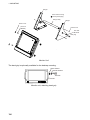
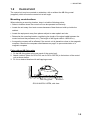
Mounting procedure
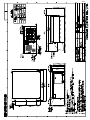
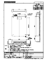
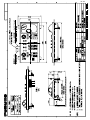
Flush mounting
Follow the procedure below to mount the monitor unit in a console panel.
1. Make cutout in mounting location referring to the outline drawing shown on the next
page.
2. Insert the monitor unit to the hole and fix it by four self-tapping screws (6x30).
3. Attach panel hooks near the fixing holes. These are used to pull out the monitor unit
from a console panel for servicing.
4. Attach four panel covers to the fixing holes.
1-1
1. MOUNTING
296 ± 1
454
4-FIXING HOLES
(79)
296 ± 1
420
506 ± 1
506 ± 1
534
490
4-φ8
FIXING HOLES
30
80
Monitor unit MU-201CE
4-φ9 FIXING HOLES
4-FIXING HOLES
(96)
313
505
313
471
570
554
570
598
30
80
Monitor unit MU-231CE
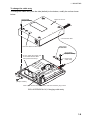
Flush mounting of monitor unit
Panel hook
Panel cover
Fixing screw
Attaching panel hook and panel cover
Note: If you need to remove the monitor unit from the panel, remove the four panel covers
with your fingernail and use two panel hooks supplied as accessories to lift the
monitor unit.
1-2
1. MOUNTING
Desktop mounting
Use the optional accessories to mount the monitor unit on a desktop.
• Necessary parts
For MU-201CE: FP03-09820 (Code No.: 008-535-560)
For MU-231CE: FP03-09830 (Code No.: 008-536-020)
Contents of FP03-09820/09830
Name
Type
Code No.
Qty
Remarks
Hanger L
03-163-1111-0
100-305-140
1
Hanger R
03-163-1112-0
100-305-180
1
03-163-1113
100-305-370
1
For MU-201CE
03-163-2071
100-305-370
1
For MU-231CE
Hole plug
CP-30-HP-13
000-147-143
2
Plastic rivet
KB-13 Rivet Black
000-570-276
4
Hex. bolt
M6x25
000-802-771
4
Hex. bolt
M10x30
000-802-182
2
Spring washer
M10
000-864-261
2
Flat washer
M10
000-864-131
2
Hanger stay
1. Assemble two hangers and hanger stay with two hex bolts (M10x30), flat washers and
spring washers and cover each hex bolt with hole plug.
2. Fix the above assembly to the mounting location with four hex bolts (M12, dockyard
supply).
3. Fasten the monitor unit to the mounting hanger assembly with four hex bolts (M6x25,
supplied).
4. Cover each hex bolt with a panel cover.
5. Cover each hole for hand grip with a plastic rivet (4 pcs).
1-3
1. MOUNTING
Hanger
M12 bolts for fixing
(Dockyard supply)
Hanger stay
Hanger
Panel cover
Hex bolt
(M6x25)
Plastic rivet
Hex bolt
M10x30
Hole plug
Monitor Unit
The hand grip is optionally available for the desktop mounting.
Wave washer
Rosette washer
Screw
Handle
Monitor unit, attaching hand grip
1-4
1. MOUNTING
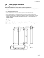
1.2
Control Unit
The control unit may be mounted on a desktop, with or without the KB fixing metal
(supplied), which mounts the control unit at an angle.
Mounting considerations
When selecting a mounting location, keep in mind the following points:
• Select a location where the control unit can be operated conveniently.
• Locate the unit away from heat sources because of heat that can build up inside the
cabinet.
• Locate the equipment away from places subject to water splash and rain.
• Determine the mounting location considering the length of the signal cable between the
control unit and the processor unit. (The length of the signal cable is 10/20/30 m).
• A magnetic compass will be affected if the control unit is placed too close to the magnetic
compass. Observe the compass safe distances on page ii to prevent deviation of a
magnetic compass.
Fixing without KB fixing plate
1. Fix the KB fixing plate to the rear panel of the control unit.
2. Attach cushions (three for RCU-018, two for RCU-015FEA) to the bottom of the control
unit as shown below.
3. Fix it to a desired location with self-tapping screws.
KB fixing plate
Cushion
RCU-018/0RCU-15FEA, side view
1-5
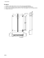
1. MOUNTING
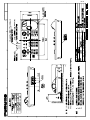
Fixing without KB fixing metal
1. Drill four mounting holes of 5 mm diameter referring to the outline drawing at the back of
this manual.
2. Fix the control unit with four screws (M4) from under side of the desktop. (The M4
screws with a sufficient length for the thickness of the desktop should be provided
locally.)
180
136±1
#70
4-M4 (Fixing holes)
(bottom)
308±1
398
RCU-018
24
32
F3
180
136±1
F1
F2
F4
110±1
160
RCU-015FEA/16
1-6
4-M4 (Fixing holes)
(REAR)
1. MOUNTING
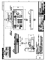
Flush mounting
Use the optional flush mount kit FP03-09870 to mount the control unit RCU-018/015FEA
and/or RCU-016 to a console panel.
Name: Flush mount kit
Type: FP03-09870
Code No.: 008-535-630
No.
Name
Type
Code No.
Qty
1
Mount plate
03-163-7531
100-306-260
4
2
Hex. nut
M5
000-863-206
4
3
Wing screw
M5x40
008-047-990
4
1. Prepare a cutout in the mounting location as shown in the figure below.
170±2
176±2
388 ±2
150±2
For RCU-018
For RCU-015FEA/16
Set the control unit to the cutout.
Screw four wing bolts into hex. nuts.
Screw the above wing bolts into mounting plates.
Attach the mounting plate to the control unit with four screws (M4x12, supplied with the
control unit) from the bottom side.
6. Fasten four wing screws, and then fasten hex. nuts to fix four wing screws.
RCU-018
A
171
#100
53
(P)
#100
A
#70
92
53
#70
86
(P)
2.
3.
4.
5.
RCU-015FEA/RCU-16
1-7
1. MOUNTING
To connect RCU-016 in series with RCU-018
1. Pass the cable from the RCU-016.
Small hole at mid is used
for ECDIS SYSTEM FAIL.
2. Connect the connector
of the cable to J502.
3. Clamp the copper part of the cable with the cable clamp.
Inside of RCU-018
1-8
1. MOUNTING
To change the cable entry
To change the cable entry from the side (default) to the bottom, modify the unit as shown
below.
Screw M3X8
(Torque 0.78Nm)
Bottom of the unit
2. Pull out the cable.
3. Pass the cable from this hole.
Cable clamp
03-163-7804
Screw M4X8
(Torque 1.47Nm)
4. In here, clamp the copper part
of the cable with the cable
clamp removed at step1.
1. Remove the
cable clamp.
(Torque 1.47Nm)
J522: If you connect RCU-016 in series with RCU-015FEA, plug in here.
RCU-015FEA/RCU-016, Changing cable entry
1-9
1. MOUNTING
1.3
Processor Unit
Mounting considerations
When selecting a mounting location, keep in mind the following points:
• Locate the processor unit away from heat sources because of heat that can build up
inside the cabinet.
• The vibration at the mounting location should be minimum.
• Locate the equipment away from places subject to water splash and rain.
• Leave sufficient space at the sides and rear of the unit to facilitate maintenance.
• A magnetic compass will be affected if the processor unit is placed too close to the
magnetic compass. Observe the compass safe distances on page ii to prevent deviation
of a magnetic compass.
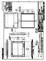
Mounting procedure
#100
1. Attach two mounting plates to the processor unit with 14 screws (M4X8, supplied).
2. Fix the unit with four M6 bolts, or self-tapping screws (local supply).
(122)
52
150+1
531
399
409
150 1
6- 8 FIXING HOLE
440 1
470
#100
404
#100
Processor unit
1-10
176
173
PROCESSOR UNIT
1. MOUNTING
1.4
LAN Adapter/B Adapter
Mounting considerations
When selecting a mounting location, keep in mind the following points:
• Locate the adapter away from heat sources because of heat that can build up inside the
cabinet.
• The vibration should be minimal.
• Locate the equipment away from places subject to water splash and rain.
• Leave sufficient space at the sides and rear of the unit to facilitate maintenance.
• A magnetic compass will be affected if the adapter is placed too close to the magnetic
compass. Observe the compass safe distances on page ii to prevent deviation of a
magnetic compass.
LAN adapter
1. Unfasten a pan head screw to remove the cover from the LAN adapter.
2. Fasten four self-tapping screws (M3) to fix the LAN adapter to the mounting location.
3. Reattach the cover.
42
170+0.5
36
293
4
206
#50
#50
#150
20
255 0.5
4- 5 Fixing hole
LAN adapter
1-11
1. MOUNTING
B adapter
1.
2.
3.
4.
Unfasten a pan head screw to remove the cover from the B adapter.
Remove six pan head screws to remove the ADAPTER B Board (220615)
Fasten three self-tapping screws (M3) to fix the LAN adapter to the mounting location.
Reattach the cover.
42
170+0.5
36
293
206
#50
#50
B adapter
1-12
#150
20
255 0.5
4- 5 Fixing hole
4
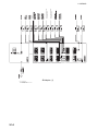
2. WIRING
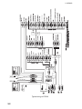
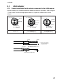
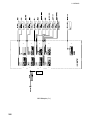
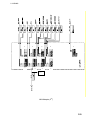
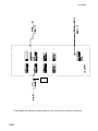
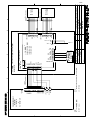
2.1
Wiring
(Two units for CONNING Type)
Monitor Unit
MU-201CE
(FEA-2107)
MU-190
(FEA-2107-D)
MU-231CE
(FEA-2807)
MU-231
(FEA-2807-D)
100-230 VAC
DVI-D/DSINGLELINK cable or RGB (HD15)
5 m/10 m
DSUB9P-DSUB9P cable
5 m/10 m
LAN Adapter
EC-1010
(Max. 2 units)
MOD-Z072-020 cable
(2 m)
FAR-2107/2807
series
Other Radar
HUB-100
Processor Unit
EC-1000C
(Max. 2 units)
MOD-Z072-020 cable
(2 m)
NH8P-DSUB15BNC2 cable
10/20/30 m
(RADAR OVERLAY Type only)
100-230 VAC
NFKVV-SB03-2PL2000A
(2 M)
TTYCS-4
ARPA RADARS
TTYCS-1
POSITION-FIXING
TTYCS-4
TRACK PILOT
TTYCS-1
LOG/DUAL-AXIS LOG
TTYCS-4
AIS
TTYCS-1
GYRO COMPASS
DPYCY-1.5 24 VDC
PR-62
MPYC-7
XH10P-DS-5P cable
(10 m/20 m/30 m)
100/230 VAC
GYRO COMPASS
(SYNCHRO, STEPPER)
TTYCS-4
LOG (200 P/NM)
TTYCS-1
ANALOG INPUT (8 channel)
TTYCS-1
ALARM OUTPUT (8 channel)
TTYCS-4
THRUSTER/RUDDER/
ENGINE/AIR PRESSURE
F1
F2
or
F3
F4
RCU-015FEA
Control Unit
RCU-018
ALARM OUT
DPYCY-1.5
XH10P-W-5P-A cable
(10 m/20 m/30 m)
24 VDC
PR-62
100/230 VAC
B Adapter
EC-1020
(CONNING/CONNING RADAR OVERLAY Type only)
F1
F2
F3
F4
Remote Control Unit
RCU-016
2-1
OPERATOR FITNESS
OPERATOR FITNESS
ACK OUT
2. WIRING
DVI-D or RGP (HD15)
Typical wiring of ECDIS
2-2
ECDIS
PROCESSOR
OPERATOR
FITNESS
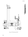
2. WIRING
LAN RADAR 1
HUB-100
LAN RADAR 2
LAN RADAR 3
No.2 ECDIS
Wiring of 1st ECDIS (One LAN adapter)
2-3
2. WIRING
ECDIS
PROCESSOR
RGB (HD15) or DVI-D
Wiring of 2nd ECDIS (backup ECDIS)
2-4
2. WIRING
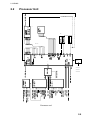
2.2
Processor Unit
x2
USB
VGA or DVI
lAN 1
HUB-100
2
LAN RADAR 1
LAN RADAR
LAN RADAR 3
Processor unit
2-5
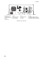
2. WIRING
10
14
1
3
5
2
4
6
7 11
15
9
16
8
12
1: CONTROL HEAD
2: RADAR UNIT
(for chart radar only)
3: COM 1
4: PARALLEL
5: USB 1
6: USB 2 or nothing
7: DVI 2 (option)
8: VGA 2 (option)
9: DV1
10: MOUSE/KEYB.
11: VGA 1
12: LAN 2
Processor unit, rear view
2-6
13
13: LAN 1
14: RADAR VIDEO IN (option)
15: RADAR TRIGGER IN (option)
16: RADAR ANTENNA IN (option)
2. WIRING
2.3
LAN Adapter
2.3.1 Cables fabrication for the cables connected to the LAN adapter
Use the following JIS (Japanese Industrial Standards) cables or equivalent. When using the
TTYCS-4 cable, connect the appropriate cable to it to pass the cable entrance of the
adapter.
φ = 11.7 mm
φ = 16.3 mm
φ = 10.1 mm
Armor
Armor
Armor
Sheath
Sheath
Sheath
Shield
Shield
Conductor
S = 1.5 mm 2
φ = 1.56 mm
Conductor
S = 0.75 mm 2
φ = 1.11 mm
Conductor
S = 0.75 mm 2
φ = 1.11 mm
TTYCS-4
(Four twisted pairs)
DPYC-1.5
Armor
30
TTYCS-1
(Twisted pair cable)
Shield
L= Depends on equipment
connected. Measure at
the processor unit.
L
5
Vinyl tape
After exposing cores,
wind shield around the armor
.
5
Clamp here by cable clamp.
2-7
2. WIRING
J4
J2
J1
J6
J5
J3
J8
J7
LAN I/F
LAN Adapter (1st)
2-8
J9
2. WIRING
J2
J1
J4
J6
J3
J5
J8
J9
J7
LAN I/F
LAN Adapter (2nd)
2-9
2. WIRING
J2
J1
J4
J3
J6
J8
J5
J7
J9
LAN I/F
LAN-Adapter as Planning / Backup Station (only one position receiver connected)
2-10
2. WIRING
Connectors on LAN-Adapter
2-11
2. WIRING
2.3.2
Serial data channels in general
An example of serial channel (here channel 1)
Input terminals for electrical standards IEC 61162-1, RS-232 and RS-422.
RX1+
“RX+” and “RX-“ may be defined as “RX-A” and “RX-B” in IEC 61162-1.
RX1Output terminals for electrical standards IEC 61162-1 and RS-422.
TX1+
“TX+” and “TX-“ may be defined as “TX-A” and “TX-B” in IEC 61162-1.
TX1TX1
Output terminals for electrical standard RS-232C
GND
Ground terminal for RS-232C
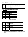
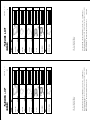
2.3.3
Standard serial data channel assignment
First LAN adapter
Channel
1
2
3
4
5
6
7
8
Relay1
Relay2
Relay3
Type bit/s
Default use
rx/tx
4800
ARPA2
rx
4800
Pos1
rx/tx
4800
Track pilot
rx/tx
4800
ARPA1
rx/tx
38400 AIS
rx
4800
Pos2
rx
38400* Gyro1
rx
4800
Log/Dual-axis log
Relay NO
Operator fitness
Relay NC
Any ECDIS alarm
Relay NC
Backup navigator
*Program version 05.xx: 4800
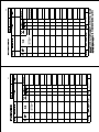
Second LAN adapter
Channel
9
10
11
12
13
14
15
16
Relay4
Relay5
Relay6
Default use
Route Backup
Engine Control
AMWSS
Navtex (Not available for program version 05.xx)
B-Adapter
Echo Sounder
Wind Sensor
Water temp
Waypoint approach
Outside channel limit
Depth below limit
*Program version 05.xx: 4800
Note: For Relay 2 to 6: Polarities are depending on Relay outputs settings (Normal open or
Normal Close) of “Alarm Inputs+Outputs/AMWSS”. (Not available for program version
05.xx)
2-12
Type bit/s
rx/tx
4800
rx
4800
rx/tx
4800
rx/tx
4800
rx/tx
38400
rx
4800
rx
38400*
rx
4800
Relay NC
Relay NC
Relay NC
2. WIRING
2.4
B Adapter (EC-1000C/EC-1000C-R only)
2.4.1 Cables fabrication for the cables connected to the B adapter
Use the following JIS (Japanese Industrial Standards) cables or equivalent. When using the
TTYCS-4 cable, connect the appropriate cable to it to pass the cable entrance of the
adapter.
φ = 11.7 mm
φ = 16.3 mm
Armor
Armor
Sheath
Sheath
Shield
Conductor
S = 1.5 mm 2
φ = 1.56 mm
Conductor
S = 0.75 mm 2
φ = 1.11 mm
TTYCS-4
(Four twisted pairs)
DPYC-1.5
= 13.2 mm
Sheath
Armor
φ = 10.1 mm
Armor
Sheath
Sheath
Insulator
Shield
Conductor
S = 0.75 mm 2
φ = 1.11 mm
Conductor
S = 1 mm 2
= 1.29 mm
TTYCS-1
(Twisted pair cable)
MPYC-7
Armor
30
Shield
L= Depends on equipment
connected. Measure at
the processor unit.
L
5
Vinyl tape
After exposing cores,
wind shield around the armor
.
5
Clamp here by cable clamp.
2-13
NAVIGATION SENSOR ALARM
CLOSED=NO ALARM
BACKUP NAVIGATOR ALARM
CLOSED=NO ALARM
ACK OUT
CLOSED=OUTPUT
2. WIRING
B Adapter (1)
No.1
LAN
adapter
CH5
No.1
LAN
adapter
CH4 or
No.2 LAN adapter CH11, CH12 or CH13
or No.2 LAN adapter CH13
2-14
2. WIRING
Need isolator if connect any analog voltage or current.
2-15
2. WIRING
Connectors on B-Adapter
2-16
2. WIRING
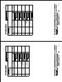
2.4.2
Interface
Status output channels in general
Channel
1 (STO1)
2 (STO2)
3 (STO3)
4 (STO4)
5 (STO5)
6 (STO6)
7 (STO7)
8 (STO8)
State
ACK OUT
ROUTE MONITOR: OUTSIDE CHANNEL LIMIT
ROUTE MONITOR: WAYPOINT APPROACH
ECHO: DEPTH BELOW LIMIT
BACKUP NAVIGATOR ALARM
NAVIGATION SENSOR ALARM
OPERATOR FITNESS
ANY ECDIS ALARM
Pitot log
Pitot log input is for 200 pulses/NM log signal with forward/astern flag.
LOG+
input terminals for log signal
LOGF/A+
input terminals for forward/astern signal (closed = astern)
F/AGyro
Gyro input is for stepper (6 steps per degree) of synchro (1:360).
S1
input terminals for gyro phase signals (stepper & synchro)
S2
S3
S0
input terminal for stepper common signal
R1H
input terminals for synchro reference signal
R1L
R1H & R2 for high synchro voltage reference (135-90 VAC)
R2
R1L & R2 for low synchro voltage reference
2-17
2. WIRING
Analog interface
Analog channels in general
An example for analog channel (here, channel 1)
REF1+
A1IN
2 kohm
SGND
REF1STI1
GND
A1IN
SGND
input terminals for analog signal
REF1+
REF1-
reference output terminals
STI1
GND
input terminals for status (open = operating, in use, etc.)
Analog channel assignment
channel usage
1
rudder feedback
2
R.O.T. gyro
3
RPM 1
4
PITCH 1
5
RPM 2
6
PITCH 2
7
BOW THRUSTER
8
STERN THRUSTER
Status input channels assignment
Channel
State
9
ALARM ACK.
10
BUZZER STOP
11 to 16
Not used.
2-18
alternative usage
second rudder feedback
engine start air pressure
fuel consumption
air pressure
2. WIRING
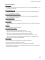
2.5 Radar Overlay
(EC-1000C-R/EC-1000C-CR only)
Radar Overlay has input for one set of radar signals. Radar Overlay can be used to read
the picture from three different radar transceivers, because it has two status inputs which
change the following characteristics of the Radar Overlay:
• Video gain operating area (low and high voltage)
• FTC adjust operating area (low and high voltage)
• STC adjust operating area (low and high voltage)
• STC curve length and shape
• Number of azimuth pulses per 360º
• Radar antenna headline detector offset
• Radar trigger range offset
• Offset of the radar antenna from the conning position
Following characteristics of the Radar Overlay are common for all radar transceivers:
• Video polarity (positive or negative) and impedance (hi-Z or 75Ω)
• Trigger active edge (positive or negative) and impedance (hi-Z or 75Ω)
• Headline polarity (positive or negative)
• HI and LO video detection level difference
If you want to utilize multiple radar transceivers, then you must have a radar interswitch
outside the ECDIS. The inter switch reports to the radar transceiver currently in use to the
status inputs of Radar Overlay.
To connect the Radar Overlay (in the processor unit) to the radar, use the cable NH8P―
DSUB15BNC cable (option). Note that XH8P-NH8P cable is necessary when the optional
radar switch is used.
2-19
2. WIRING
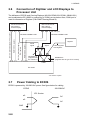
2.6
Connection of Digitizer and LCD Displays to
Processor Unit
The brilliance of ECDIS and Conning Displays (MU-201CE/MU-231CE/MU-190/MU-231)
can be adjusted at EC-1000C by connecting to COM1 port as below. Also, COM1 port is
used for connection of Digitizer (CALCOMP Drawing Board III).
MU-201CE/231CE
MU-190/231
ECDIS Display
MU-201CE/231CE
MU-190/231
ECDIS Display
D-sub 9 pin
DSUB9P-DSUB9P-L5M*
DSUB9P-DSUB9P-L5M*
RGB 10/30 m (option)
Digitizer
DVI 5 m (standard supply)/
10 m (option)
RGB 10/30 m (option)
DVI 5 m (standard supply)/10 m (option)
D-sub 9 pin
Serial
signal
Serial
signal
DSUB9P3-B
(supplied with
EC-1000C-C)
Cable supplied
with Digitizer
DSUB9P3-A
(supplied with all type of EC-1000C)
COM1
EC-1000C
*10 m/30 m: option
2.7
Power Cabling to ECDIS
ECDIS is powered by 100-230 VAC power. See figure below for cabling.
ECDIS
ACL
ACN
GND
2-20
100-230VAC
IEC Socket
IEC Socet
LAC
N
AC
2. WIRING
2.8
Ethernet Cable Connection
One ECDIS can be connected to another ECDIS with optional cable MOD-Z072-020+,
which is 2 m long. If you need a longer cable, connect LAN (Local Area Network), using
RJ45 connectors. Cable used between two ECDIS devices should be UTP (Unshielded
Twisted Pair). See figures and tables below.
RJ45 Female connector (at the ECDIS)
RJ45 Male connector (at the cable)
Pin out of female connector at ECDIS
Pin
1
Name
Description
Wiring of the twisted cable
First end Pin
Second end Pin
TX+
Transmit Data +
1
3
2
TX-
Transmit Data -
2
6
3
RX+
Receiving Data +
3
1
4
N/C
Not connected
6
2
5
N/C
Not connected
6
RX-
Receive Data -
7
N/C
Not connected
8
N/C
Not connected
2-21
2. WIRING
2.9
EMI Core for Processor Unit
When connecting the LAN cable MOD-Z072-020+ (supplied) to the processor unit
EC-1000C, attach the EMI core (type: RFC-10, supplied as installation materials) to that
cable as shown below.
Fasten core with two cable
ties to fix the core.
10 cm
EC-1000C
to LAN Adapter
EC-1010
RJ45
EMI core
RFC-10
MOD-Z072-020+ cable
When no radar is connected
Fasten core with two cable
ties to fix the core.
10 cm
to LAN Adapter EC-1010
RJ45
to Radar FAR-2xx7
EC-1000C
RJ45
EMI core
RFC-10
MOD-Z072-020+ cable
When a radar is connected
2-22
3.
ADJUSTMENTS
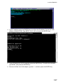
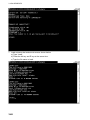
3.1
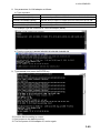
How to Set IP Address for ECDIS
ECDIS has two local area network interfaces, and Interface IP address for the No.2 ECDIS
has to be changed. To set the IP addresses, run WindowsXP as follows.
1. Open the cover on the front panel of the processor and connect the service keyboard
there.
2. Turn the power on.
3. While pressing down the Alt key, press the Tab key on the service keyboard several
times to show ECAWATCH window.
4. Release the keys and press the “Shutdown the ECDIS” button on the screen
immediately.
5. Click x mark to close Control Head window.
6. Press the Alt and F4 keys simultaneously to show the WindowsXP screen.
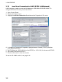
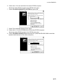
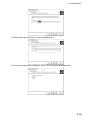
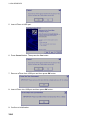
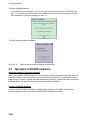
3.1.1
Local Area Connection for LAN 1 (ARPA Radar Network)
To configure IP Address for Local Area Connection interface, proceed as follows:
1. Open the control panel of the Window.
2. Double click the Network Connection icon.
3. Highlight “Local Area Connection”, and then select Properties in File menu.
0
4. In “Local Area Connection Properties”, highlight Internet Protocol (TCP/IP) in general
tab, and then press the Properties button.
5. Set IP Address as 172.31.3.29 (for the first ECDIS) or 172.31.3.30 (for the second
ECDIS).
6. Set Subnet mask as 255.255.0.0.
7. Press the OK button to close the window.
3-1
3. ADJUSTMENTS
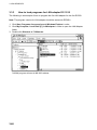
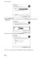
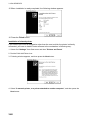
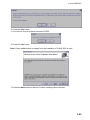
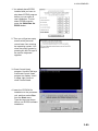
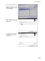
3.1.2
Local Area Connection for LAN2 (ECDIS LAN Network)
LAN2 interface is used to connect a LAN Adapter or HUB-100 to ECDIS EC1000C. To
configure IP Address for this, proceed as follows:
1. Open Control Panel.
2. Double click Network icon.
3. Highlight Local Area Connection 2 and then select Properties in File menu.
0
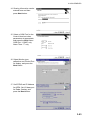
4. In Local Area Connection 2 Properties, highlight Internet Protocol (TCP/IP), and then
press Properties button.
5. Set IP Address as 10.0.0.180 (for the first ECDIS) or 10.0.0.181 (for the second ECDIS).
6. Set Subnet mask as 255.255.0.0.
7. Click the OK button to close the window.
To use the EC-1000C as No.2, see page 3-99.
3-2
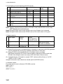
3. ADJUSTMENTS
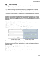
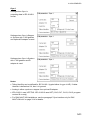
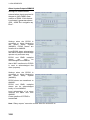
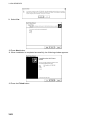
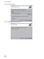
3.2
Parameters
NOTE: Special attention to following topics is required to maintain "Consistent Common
Reference System."
• The values of center and conning positions depend on size and geometry of the ship.
• Offsets from Antenna Position to Conning Position of Position Sensors depend on the
location of position sensor antennas.
• Offsets from Antenna Position to Conning Position of Radars depend on the location of
radar antennas.
Installation parameters have limited access, and are controlled by an Authorizing key disk
(supplied). The Authorizing key disk is a floppy which contains the necessary key to allow
access into editing of the installation parameters. Do the following to access the installation
parameters.
1. Insert the “Authorization key disk” to the processor unit.
Note that the installation parameters have limited access, which is controlled by the
Authorization key disk supplied.
2. Press the MENU key on the control unit to open the menu.
3. Roll the wheel to choose Initial Settings, and then push the wheel.
4. Locate the cursor on the ► next to INITIAL SETTINGS to show Initial settings menu.
5. Roll the wheel to choose Installation parameters and push the wheel.
(Program version 05.xx)
(Program version 06.xx)
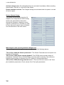
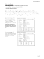
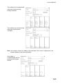
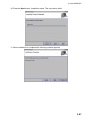
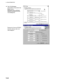
There are several buttons in this dialog box, and they are described below:
Set parameters defaults: This restores Installation parameters which are saved as a
backup copy by service personnel. Use this function if you are not sure about Installation
parameters values.
Sensor channel usage: The CH and sensors are shown.
Set Single Workstation Mode: This button is used to set Workstation to operate as a
single workstation.
Workstations
This button is used to define names, source of sensors and location of Access Server of
Workstations if two workstations are installed.
3-3
3. ADJUSTMENTS
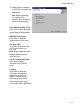
Activate changes now: The changed settings are activated immediately. When canceling
the activation, click the “X” at the top of the screen.
Restart needed to activate: The changed settings are activated when the power is turned
off and on again.
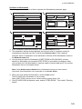
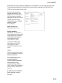
Sensor Channel Usage
This shows how the serial channels of A
adapters are configured and which analog
sensors are connected to the system
through the B adapter. Notation x (nnnn)
(right is an example of x (GYRO2)) is used
to show that some sensor data is collected
from the data flow of the main sensor.
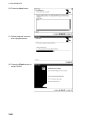
What happens after pressing Activate changes now
After pressing Activate changes now, you may get one of the following alarms.
"700 (V.05.xx: 4000) No Sensor parameters": The Sensor Parameters are corrupted. Use
backup of Parameters.
"600 (V.05.xx: 3000) Param change disabled": The ECDIS cannot accept change of
parameters if Kalman Filter is ON or ECDIS is currently used for steering. Use manual or
autopilot steering and turn Kalman Filter OFF when you change parameters.
"459 (V.05.xx: 2459) Steering parameter error": There are incorrect values in the Track
pilot installation parameters. Check values of the Track pilot parameters.
3-4
3. ADJUSTMENTS
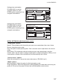
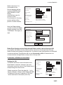
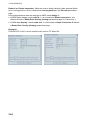
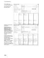
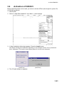
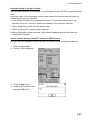
Definition of Workstation
Below is a generic description of how to operate the Workstation parameter page.
Installation parameters
Sensor Parameters
x
Workstation names
Edit Workstation names
EC1000C-0001
PORT ECDIS
Set parameter defaults
Sensor Channel usage
Workstation parameters
Set Single Workstation Mode
Sensor source default
Planning station
Location of Access Server
Logical name
Network name
EC1000C-0001
EC1000C-0002
Workstations
Restart needed to activate
Workstation names
Edit Workstation names
Sensor source default
Planning station
Logical name
PORT ECDIS
EC1000C-0001
Location of Access Server
Network name
EC1000C-0001
EC1000C-0002
Remove
Remove all
Single
Workstation
Mode
No sensor master selected
No control master selected
PORT ECDIS
Save
OK
Close installation parameters
Activate changes now
x
x
Save
Remove
Remove all
Workstation names
Edit Workstation names
STBD ECDIS
Sensor source default
Planning station
Logical name
PORT ECDIS
STBD ECDIS
EC1000C-0002
Location of Access Server
Network name
EC1000C-0001
EC1000C-0002
OK
Single
Workstation
Mode
x
Save
Remove
Remove all
OK
Single
Workstation
Mode
1. In the Installation parameters window, click the Workstations button.
2. The workstation names window appears and it shows a list of computer names for
workstations connected via LAN, in the list box Network name. Click a desired
computer name of workstation to set workstation function at Edit Workstation names in
the Network name field.
3. You can enter an alias for Workstation (PORT ECDIS as EC1000-0001) to better
describe a Workstation (for example PORT ECDIS for workstation located port side).
You can also set if the Workstation is used as master of sensor data and if it is used as
Workstation that run an Access Server.
Note: Check Sensor source default for the Workstation where you have sensors
connected. One Workstation can be selected to run Access Server.
4. When you have defined a Workstation, click the Save button.
The EC-1000C-0001 Workstation is set as below:
Alias: PORT ECDIS, Sensor source: default setting, Access Server: ON
5. Click EC1000C-0002 at Network name, and set “STBD ECDIS”. Then check “Planning
station”.
3-5
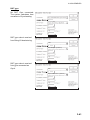
3. ADJUSTMENTS
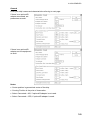
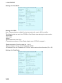
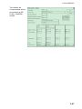
Examples:
Settings when workstation
EC1000C-0001 is used as a
stand-alone system.
Workstation names
Edit Workstation names
PORT ECDIS
Sensor source default
Planning station
Logical name
PORT ECDIS
EC1000C-0001
Location of Access Server
Network name
EC1000C-0001
EC1000C-0002
x
Save
Remove
Remove all
OK
Single
Workstation
Mode
Settings when workstation
EC1000C-0001 is used as
navigation station in a two
ECDIS system consisting of one
navigation and one planning
workstation.
Workstation names
Edit Workstation names
NAVIGATION
Sensor source default
Planning station
Logical name
NAVIGATION
PLANNING
EC1000C-0001
Location of Access Server
Network name
EC1000C-0001
EC1000C-0002
x
Save
Remove
Remove all
OK
Single
Workstation
Mode
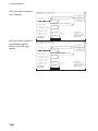
Settings when workstation
EC1000C-0002 is used as
planning station in a two ECDIS
system consisting of one
navigation and one planning
workstation.
Workstation names
Edit Workstation names
PLANNING
Sensor source default
Planning station
Logical name
NAVIGATION
PLANNING
EC1000C-0002
Location of Access Server
Network name
EC1000C-0001
EC1000C-0002
x
Save
Remove
Remove all
OK
Single
Workstation
Mode
3-6
3. ADJUSTMENTS
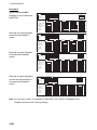
Settings when workstation
EC1000C-0001 is used as
navigation station in a two
ECDIS system consisting of two
navigation workstations.
Workstation names
Edit Workstation names
PORT
Sensor source default
Planning station
Logical name
PORT
EC1000C-0001
Location of Access Server
Network name
EC1000C-0001
EC1000C-0002
x
Save
Remove
Remove all
STBD ECDIS
OK
Single
Workstation
Mode
Settings when workstation
EC1000C-0002 is used as
navigation station in a two
ECDIS system consisting of two
navigation workstations.
Workstation names
Edit Workstation names
STBD ECDIS
Sensor source default
Planning station
Logical name
PORT
STBD ECDIS
EC1000C-0002
Location of Access Server
Network name
EC1000C-0001
EC1000C-0002
x
Save
Remove
Remove all
OK
Single
Workstation
Mode
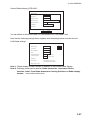
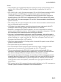
INITIAL SETTINGS for Multi-workstation mode
“Usage rights” options
Master: The workstation with this setting can open user-created data (User chart, Notes,
Route), using the monitor mode.
Plan: This option creates planning data. “Plan” cannot be used to open data in the monitor
mode.
Multi (Slave): The workstation with this setting can open user-created data, using the
monitor mode. Use this option to assign usage rights to multiple workstations. When you set
a workstation to Master, other workstation(s) are automatically set as Slave.
“Sensor source” options
Select the workstation to use as the sensor data source (“EC1000C-xxxx”).
“Mode” options
Multi workstation: Select this option for Multi-workstation mode.
Single workstation: Select this option when loading/updating the chart data, and turning the
power off. Do not turn the power off when the multi-workstation mode is active.
3-7
3. ADJUSTMENTS
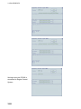
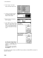
Opening each parameter dialog box
1. Locate the cursor on the ► mark on the drop-down list.
2. Choose an item you want to set, by scrolling the list.
3-8
3. ADJUSTMENTS
General
Enter your ship’s name and characteristics referring to next page.
If there is no optional B
adapter connected, set
parameters as such.
If there is an optional B
adapter, set the equipment
as such.
Notes:
• Center position is geometrical center of the ship.
• Conning Position is the point of observation.
• Select Connected = NO, if optional B adapter is not used.
• Select Connected = YES, if optional B adapter is used.
3-9
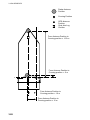
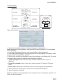
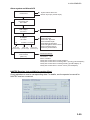
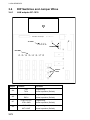
3. ADJUSTMENTS
Radar Antenna
Position
Conning Position
Breadth = 30 m
GPS Antenna
Position
Dual Axis Log
Position
From Center Position to
Bow Position =100 m
Lenght = 200 m
Length=200 m
From Center Position to
Dual Axis Log Position = 70 m
Center
Position
From Center Position to
Conning position = -60 m
From Center Position to
Stern Position = -100 m
Side Position = 15 m
From Center Position to
sidewise Conning position = 10 m
3-10
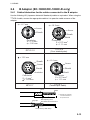
3. ADJUSTMENTS
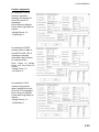
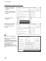
Gyro 1
Settings when Gyro is
outputting data in IEC-61162-1
format.
Settings when Gyro is Stepper
or Synchro with 1:360 gearbox
and optional B adapter is used.
Settings when Gyro is Synchro
with 1:180 gearbox and B
adapter is used.
Notes:
• Talker identifier can be defined for IEC 61162-1 (typical talker for gyro is HE). If talker
identifier is defined as XX, then it is ignored.
• Analog is either synchro or stepper from optional B adapter.
• IEC-61162-1 uses HDT/THS. IEC-61162-2 uses HDT (CH5, CH7, CH13, CH15, program
version 06.xx only)
• For DNV NAUT-AW installations, see the paragraph "Gyro interface only for DNV
NAUT-AW rule" on page 3-14 for details.
3-11
3. ADJUSTMENTS
Gyro 2
Settings when Gyro 2 is
receiving from Trackpilot.
If connected TCS.
(BSH type approved)
Settings when Gyro 2 is
receiving through Trackpilot.
If connected EMRI TCS.
(DNV NAUT-AW).
Settings when Gyro 2 is not
connected.
3-12
3. ADJUSTMENTS
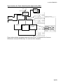
Gyro interface for Track Control System approved by BSH
Gyro 2
Gyro 1
Gyro
ARPA
Repeater
ARPA
Gyro selector
Common
Distribution
Unit
Gyro 1 or
Gyro 2
Gyro 1
IEC-61162-1 ($XxHDT) or
Stepper/Synchro
Gyro 2
Trackpilot
Track
Pilot
Gyro 1
RADAR
ARPA
ECDIS
Gyro 2
Trackpilot
Figure above shows an example where ECDIS Gyro 1 is received from Common
Distribution Unit and ECDIS Gyro 2 is received from trackpilot.
3-13
3. ADJUSTMENTS
Gyro interface only for DNV NAUT-AW rule
Gyro 2
Gyro 1
Gyro
ARPA
Repeater
ARPA
First priority
Gyro selector
Common
Distribution
Unit for Gyro
Selected gyro
(Gyro 1 or Gyro 2)
ARPA
RADAR
ARPA
Gyro 1
Gyro 2
IEC-61162-1 ($XxHDT)
or
Stepper/Synchro
Gyro 2
Gyro 1
Gyro 1
ECDIS
Select
Track Pilot
Trackpilot
Gyro 2
Gyro 2 through Trackpilot
Figure above shows an example where ECDIS Gyro 1 is received directly from Gyro 1 and
ECDIS Gyro 2 is received through Track Pilot.
Notes: For receiving Gyro 2 through Trackpilot:
•
Software of AEU511 for the Trackpilot must be "SEM200 Version Aeu2_3 Compiled
13-04-2004 11:39".
•
MPI31 must be "MIP2 Version Mip2 Compiled 12-03-2004 16:38".
•
ExtendedPessa should be checked.
3-14
3. ADJUSTMENTS
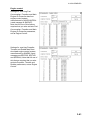
Log
Settings when log is using
Analog Pulses 200 p/nm. Note
that log is used for water speed
component if the dual-axis log is
available.
4
Analog Pulse (uses B-Adaptor)
Settings when log is single axis
pilot log transmitting
IEC-61162-1. Message used is
VBW.
8
Settings when log is used to
find out water speed component
from a dual-axis log using
IEC-61162-1. Sensor log uses
water tracking values of VBW
message.
8
Notes:
• Talker identifier can be defined for IEC 61162-1 (typical talker for log is VD). If talker
identifier is defined as XX, then it is ignored.
• Analog pulses are from optional B-Adapter.
3-15
3. ADJUSTMENTS
Dual-axis log
Settings when using
IEC-61162-1.
Connected:
YES
Adapter Channel:
for Ahead
Settings when no dual-axis log
is available.
Connected:
NO
Adapter Channel
8
for Ahead
Notes:
• Talker identifier can be defined for IEC 61162-1 (typical talker for dual axis log is VD). If
talker identifier is defined as XX, then it is ignored.
• IEC 61162-1 uses VBW or VTG.
• If you selected VBW message, then bottom track is available from dual-axis log and water
track could be available from log.
3-16
3. ADJUSTMENTS
Radar Echo Overlay
Radar Echo Overlay can be received by ECDIS in two ways:
• through Radar Overlay card fitted in ECDIS
• through LAN from FAR-2x07
Radar Echo Overlay (analog) through Radar Overlay card fitted in ECDIS
This menu does not appear if Analog Echo Overlay is set for "No use" during installation.
Configuration for Radar Echo Overlay (analog), when Radar overlay card fitted in ECDIS, is
done using "Radar Echo Overlay (Analog)" parameter settings.
Here is an example, when
Radar Transceiver is not
connected (Connected as
NO) through Radar overlay
card fitted in ECDIS.
NOTE: You have to define all
three Radar transceivers
whether they are connected
through the Radar overlay or
not.
Here is an example of a
mast- mounted S-band radar,
when mast is in about same
position as the conning
position.
0
0
3-17
3. ADJUSTMENTS
Here is an example of a bow
mounted radar with large
distance from the conning
position. Bearing and Range
offsets are used to align
radar and chart displays.
5
150
Here is an example of a
mast-mounted X-band radar,
when mast is in about same
position as the conning
position. Bearing and Range
offsets are used to align
radar and chart displays.
0
0
Radar Overlay has status inputs which are used to select between 3 different setups for
parameters. This arrangement allows installation of three different radar transceivers and
antennas. Fox example a normal set of one S-band and one X-band radar on a mast and
then a third radar at the bow. See examples above.
Each radar can have an antenna with different amount of pulses per revolution. Also
operational area of FTC (Rain clutter), STC (Sea clutter) and gain is separately defined for
each radar. Offsets defined here are also used indirectly by the radar display.
3-18
3. ADJUSTMENTS
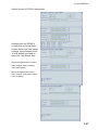
Radar Echo Overlay (LAN) from FAR-2xx7 and FCR 2xx7 series radar through LAN
The following settings are for Radar Echo Overlay (LAN) received from FAR-2xx7 and
FCR-2xx7 series radar through LAN.
Set the radar connected
through the network. The
radar echo set “Connected:
Yes” here can be overlay
displayed on the chart. When
multiple radar are set to
“Yes”, select one at RADAR
OVERLAY (Main
Menu>Radar).
Radar transceiver:
Select the radar to set.
Device Interface:
IMO Radar: For FAR-2xx7,
route information loading; OK
Chart Radar: For FCR-2xx7,
route information loading; Chart Radar with INS:
For FCR-2xx7, route
information loading; OK
Chart Radar with CCRS:
For FCR-2xx7, route
information loading; OK (all
route)
Label:
Set the name for each radar
(max. 6 characters) to use on
RADAR OVERLAY.
From Radar antenna to
Conning position:
Enter the distance between
antenna and conning
positions (Range: -500 to
+500). Upper: port-starboard
direction, lower: bow-stern
direction
IP address, Port numbers,
Radar display number:
Not used.
3-19
3. ADJUSTMENTS
If Radar overlay is not
received through LAN, set
Connected as NO for each
transceiver (1-4).
Radar transceiver 1 is
Connected as Yes.
Device Interface defines
source of RADAR target
(IMO RADAR or Chart
Radar).
Label defines name for
source of video.
From Antenna to Conning
position defines offset
position of radar antenna.
Note that Radar display
number is defined in Radar
Display settings in the field at
right "LAN Radar". See figure
below.
Edit parameters - Radar Echo Overlay/Communication (LAN)
OK
Radar transceiver
1
Connected
NO
Device interface
IMO Radar
Label
MASTS
From Radar antenna
to Conning position
2
m {+Stbd, -Port}
20
m {+Bow, -Stern}
IP address
172.31.3.6
Port numbers
10024 for Radar echo output
10028 for Radar communication
Radar display number
1
Edit parameters - Radar Echo Overlay/Communication (LAN)
OK
Radar transceiver
1
Connected
YES
Device interface
IMO Radar
Label
MASTS
From Radar antenna
to Conning position
2
m {+Stbd, -Port}
20
m {+Bow, -Stern}
Cancel
IP address
172.31.3.6
Port numbers
10024 for Radar echo output
10028 for Radar communication
Radar display number
1
Edit parameters - Radar Display
Radar Displays
Radar Display
Display 1
Connected
YES
Adapter Channel
4
Device Interface
FURUNO FAR-2x07 (LAN)
Rx Talker Identifier
RA
LAN Radar
1
IP address
172.31.3.6
OK
3-20
Cancel
Cancel
3. ADJUSTMENTS
Radar transceiver 2 is
Connected as Yes.
Device Interface defines
source of RADAR target
(IMO RADAR or Chart
Radar).
Label defines name for
source of video.
From Antenna to Conning
position defines offset
position of radar antenna.
Note that Radar display
number is defined in Radar
Display settings in the field
"LAN Radar". See figure at
right.
Edit parameters - Radar Echo Overlay/Communication (LAN)
OK
Radar transceiver
2
Connected
YES
Device interface
IMO Radar
Label
MASTS
From Radar antenna
to Conning position
2
m {+Stbd, -Port}
20
m {+Bow, -Stern}
Cancel
IP address
172.31.3.7
Port numbers
10024 for Radar echo output
10028 for Radar communication
Radar display number
2
Edit parameters - Radar Display
Radar Displays
Radar Display
Display 2
Connected
YES
Adapter Channel
1
Device Interface
FURUNO FAR-2x07 (LAN)
Rx Talker Identifier
RA
LAN Radar
2
IP address
172.31.3.7
OK
Cancel
Radar Echo Overlay received both through Radar overlay card and through LAN
It is possible that Radar Overlay video from one transceiver is received either through
Radar Overlay card (analog) or through LAN. You have to make configuration as introduced
in previous sections. Pay attention that you set Connected as NO for transceivers not
connected either through Radar overlay card or through LAN.
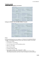
Connection of ECDIS and Chart Radar
Edit parameters - Radar Echo Overlay/Communication (LAN)
Settings for INS
The ECDIS sends the route information to the
Chart Radar in real time. However, the route
information cannot be sent to Chart Radar when it
stoops during the route monitor.
-Radar transceiver: Enter the radar No. ‘1 to 4)
-Device Interface: Choose “Chart Radar with INS”.
-IP Address: Enter the IP address of FCR-2xx7
which receives the information (33 to 36).
OK
Radar transceiver
1
Connected
YES
Device interface
Chart Radar with INS
Label
1
From Radar antenna
to Conning position
0
m {+Stbd, -Port}
0
m {+Bow, -Stern}
IP address
Port numbers
Radar display number
IP Address
Port numbers
Cancel
172.31.3.6
10024 for Radar echo output
10028 for Radar communication
1
172.31.3. 33
15003 for INS communication
3-21
3. ADJUSTMENTS
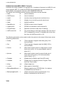
Settings for Chat Radar
Settings for CCRS
Note: These settings is available for the chart radar with version 06.01 and after.
The following data are sent from ECDIS to Chart Radar when starting the route monitor.
-Route data
-User chart
-Notes
-Sensor data other than Gyro
(These data are shown on Chart Radar display even if ECDIS is stopped.)
-Radar transceiver: Enter the radar No. (1 to 4)
-Device interface: Choose “Chart Radar with CCRS”.
-IP Address: Enter the IP address of FCR-2xx7 which receives the information (33 to 36).
Settings for Chart Radar
3-22
3. ADJUSTMENTS
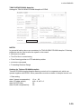
Radar Displays
There are 6 basic device interface alternatives:
1) Device interface FURUNO: IEC 61162-1 (TX Talker ID = II) includes all standard
messages for an ARPA radar target data receive interface. Further it also contains a lot
proprietary messages supporting integrated navigation features such as user charts,
routes, curved EBL, etc.
2) Device interface FURUNO: IEC 61162-1 (TX Talker ID = EI)includes all standard
messages for an ARPA radar target data receive interface. Further it also contains a lot
proprietary messages supporting integrated navigation features such as user charts,
routes, curved EBL, etc.
3) Device interface FURUNO: IEC 61162-1 (TX Talker ID = EC) includes all standard
messages for an ARPA radar target data receive interface. Further it also contains a lot
proprietary messages supporting integrated navigation features such as user charts,
routes, curved EBL, etc.
4) Device interface IMO IEC 61162-1 ($xxOSD, $xxTTM) uses TTM message for ARPA
radar target data receive interface and OSD message for ARPA radar speed and course
receive. It sends standard ECGLL, ECDPT and ECMVW messages to the ARPA radar.
5) Device interface FURUNO: FAR-2x07 (serial) includes all standard messages for an
ARPA radar target data receive interface. Further it also contains a lot proprietary
messages supporting integrated navigation features such as user charts, routes, curved
EBL, etc
6) Device interface FURUNO: FAR-2x07 (LAN) includes all standard messages for an
ARPA radar target data receive interface. Further it also contains a lot proprietary
messages supporting integrated navigation features such as user charts, routes, curved
EBL, etc
In the Radar Display field you can select radar displays one by one and define if they are in
use, etc.
3-23
3. ADJUSTMENTS
Radar id and Radar transceiver -fields are used to select indirectly radar antenna offsets
from Conning position, which is defined as Conning position in the General parameters
page.
In the example above there are settings for ARPA radar display 1:
• If ARPA Radar display sends radar id 1, it is connected to Radar transceiver 1 and
offset is defined in Radar Echo Overlay (Analog) parameters page for Transceiver 1.
• If ARPA radar display 1 sends radar id 2, it is connected to Radar Transceiver 2 defined
in Radar Echo Overlay (Analog) parameters page.
Example1:
FURUNO IEC 61162-1 device interface with various TX Talker IDs.
3-24
3. ADJUSTMENTS
Example 2:
Generic ARPA radar using only IMO standard message.
Example 3
FAR-28x7 ARPA radar connected with serial line.
3-25
3. ADJUSTMENTS
Example 4
Parameters for one FAR-2xx7 radar and one FCR-28x7 Chart Radar connected with LAN
Cable.
First Radar display (FAR-2xx7):
You can define to which LAN radar it is connected, at the "LAN Radar" field.
Note that the settings above together with the settings below must be done for LAN Radar
settings:
Note 1: "Radar display number" defines IP address for connected ARPA Radar Display.
Note 2: Following values can be tailored: Radar transceiver, Connected, Device
Interface, Label and From Radar Antenna to Conning Position. Leave other values as
is.
3-26
3. ADJUSTMENTS
Second Radar display (FCR-28x7):
Edit parameters - Radar Display
Radar Displays
Radar Display
Display 2
Connected
YES
Adapter Channel
1
Device Interface
FURUNO FAR-2x07 (LAN)
Rx Talker Identifier
RA
LAN Radar
2
IP address
172.31.3.7
OK
Cancel
You can define to which LAN radar it is connected at the "LAN Radar" field.
Note that the following settings above together with the settings below must be done for
LAN Radar settings:
Edit parameters - Radar Echo Overlay/Communication (LAN)
Radar Display
2
Connected
YES
OK
Cancel
Device Interface
Chart Radar
Label
MASTS
From Radar antenna
to Conning position
2
m (+Stbd, -Port)
30
m (+Bow, -Stern)
IP address
172.31.3.7
Port numbers
10024 for Radar echo output
10028 for ARPA communication
Radar display number
2
Note 1: "Radar display number" defines IP address for connected Radar Display.
Note 2: Following values can be tailored: Radar transceiver, Connected, Device
Interface, Label, From Radar Antenna to Conning Position and Radar display
number. Leave other values as is.
3-27
3. ADJUSTMENTS
Radar Antenna
Position
Conning Position
GPS Antenna
Position
Dual Axis Log
Position
From Antenna Position to
Conning position = -150 m
From Antenna Position to
Conning position = -5 m
From Antenna Position to
Conning position = 10 m
From Antenna Position to
Conning position = 12 m
3-28
3. ADJUSTMENTS
Position equipment
An example of DGPS
receiver with talker
identifier GP defined for
both GGA and VTG
messages.
Enter values for Weight
Factor and Cmg Delay as
follows.
-Weight Factor: 0.1
-Cmg Delay: 0
An example of DGPS
receiver which is able to
send IEC 61162-1 Ed. 2
messages (includes
information about Datum
of output position).
GGA+VTG
GGA+VTG
Enter values for Weight
Factor and Cmg Delay as
follows.
-Weight Factor: 0.1
-Cmg Delay: 0
An example of GPS
receiver with ignored
talker identifiers for both
GLL and VTG messages.
Enter values for Weight
Factor and Cmg Delay as
follows.
-Weight Factor: 0.1
-Cmg Delay: 0
GLL+VTG
3-29
3. ADJUSTMENTS
An example of setting for
DGPS receiver which is
able to send IEC 61162-1
Ed. 2 messages.
Enter values for Weight
Factor and Cmg Delay as
follows.
-Weight Factor: 0.1
-Cmg Delay: 0
An example of setting for
Syledis receiver.
Enter values for Weight
Factor and Cmg Delay as
follows.
-Weight Factor: 0.1
-Cmg Delay: 0
An example of setting for
Loran receiver.
Enter values for Weight
Factor and Cmg Delay as
follows.
-Weight Factor: 0.1
-Cmg Delay: 0
3-30
GLL+VTG
GGA+VTG
GLL+VTG
3. ADJUSTMENTS
Notes:
• Talker identifier can be separately defined for speed and course (VTG message) and for
position (GLL, GGA or PAT message). If talker identifier is defined as XX, then it is
ignored.
• IEC 61162-1 ed1 or ed2: GGA uses messages VTG and GGA. Recommended for DGPS.
Correct operation of a DGPS sensor requires that the system also receives VTG
(COG/SOG) message. If no VTG message is received, the system thinks that there is
something wrong in the DGPS and it downgrades the DGPS to an ordinary GPS sensor.
• IEC 61162-1 ed1: GLL uses messages VTG and GLL. Recommended for non-differential
position receivers.
• IEC 61162-1 ed2: GLL uses messages VTG and GLL. Recommended for both differential
and non-differential position receivers.
• COG delay is the delay between own ship turning and course made good in the VTG
message to detect turning. Typically values are from 0 to 15 seconds.
• Because no message has any datum indication, the user is responsible for reference
system used in the position receiver. GGA message is supposed to always be in WGS-84,
but unfortunately some manufacturers do not follow this standard.
• Only one of connected sensors is allowed to send ZDA message, which will be used to
adjust the system clock. If time difference is larger than 5 seconds and if the system is not
a part of steering (i.e., mode is not Goto Wp, Goto Track or Program Track Turn) and if
the system has Kalman filter in OFF position.
• Offset from antenna position to Conning position is essential for speed, course, drift and
predictor related calculation.
• Roll & pitch data may be enabled only with PAT.
• First two channels can also operate as general purpose outputs. Checksum related
parameters are for outputs only. Sent messages are GLL, VTG and HDT.
• There are two alternatives for IEC 61162-1 based interface: ed1 and ed2. Ed1 was
published in September 1998 and Ed2 was published in July 2000. The differences are
new datum message (DTM) and changed content of GLL position message.
• Ed2 requires that position information (in this case GLL or GGA messages) also contain
separate indication of datum used (DTM message). IMO rule states that ECDIS can only
accept position in WGS84 datum. In practice only EPFS (for example, GPS or DGPS),
which has "IEC 61162-1 Ed 2 (2000-7)" indicated in their type approval certificate can
detect Datum.
• Ed2 requires that the GLL message includes a quality indicator i.e., the GLL message can
indicate if position is based on standard GPS or differential GPS.
3-31
3. ADJUSTMENTS
Radar Antenna
Position
Conning Position
GPS Antenna
Position
Dual Axis Log
Position
From Antenna Position to
Conning position = 5 m
From Antenna Position to
Conning position = 10 m
From Antenna Position to
Conning position = -5 m
From Antenna Position to
Conning position = 10 m
Note for service engineer:
If the vessel has main and backup system, then you must yourself set proper antenna offset
for both systems. Keep in mind that they are two independent and separate systems, but
they should share common antenna offset in case that they are connected to the same
position antenna.
3-32
3. ADJUSTMENTS
Echo Sounder and Weather
OK
Cancel
YES
IEC61162-1 ($xxDBT)
YES
YES
IEC61162-1 ($xxDBT)
IEC61162-1 ($xxCDR)
14
16
12
SS
SS
SS
NO
NO
0
0
YES
NO
IEC61162-1 ($xxMTW)
10
Analog(uses B-Adapter)
8
NO
NO
Analog(uses B-Adapter)
Analog(uses B-Adapter)
6
4
0
0
0
0
0
2
0
0
0
0
0
0
2
3
7
5
Notes: (air temperature)
• Not used by this system, should have Connected = NO.
Notes: (air pressure)
• Not used by this system, should have Connected = NO.
3-33
3. ADJUSTMENTS
Wind sensor
Here is an example of a wind
sensor which is connected to
LAN Adapter channel 15.
Wind modes are defined as: The wind as measured by a wind meter is known as apparent
wind. If indicated wind includes speed compensation it is known as relative wind. If
indicated wind includes both speed and heading compensation it is known as true wind.
Definitions:
• APPARENT
Wind as measured by wind meter.
• RELATIVE
Wind includes speed compensation.
• TRUE(T)heoretical
Wind includes both speed and heading compensations.
• TRUE(=North)
Wind includes both speed compensation and North stabilization.
Notes:
• Talker identifier is ignored.
• THIES in the Device Interface is a special case.
• Calculation of true from relative can only be used if wind sensor sends TRUE wind
according to definition above.
• Source of True Wind to define what kind of wind is transmitted by weather station:
Receive (T)heoretical Wind (HDG) and calculate True wind is default.
• Style of Display to define what kind of wind is displayed on ECDIS, True wind or Relative
wind.
• Style of output to ARPA to define what kind of wind is transmitted to ARPA.
3-34
3. ADJUSTMENTS
Trackpilot, autopilot
Settings when no Trackpilot is connected:
Settings for FURUNO FAP-2000/EMRI SEM200 Trackpilot
Notes:
In general all settings above are mandatory for FURUNO FAP-2000/EMRI SEM200
Trackpilot. The following parameters can be used to tailor the system to the vessel:
• Minimum turn radius
• Turn Endline in route steering
• From Conning position to XTE calculation position
• Minimum route speed
• Manual Steering Label
• Forwarding Distance Range
• Route Check (Available when “Connected” is “YES”)
-IEC-62065 (Not required): Route Monitor is available without Route Check.
-DNV (Required by class note): Route Check is necessary to use Route Monitor.
3-35
3. ADJUSTMENTS
FURUNO FAP-2000/EMRI SEM200 Trackpilot
FURUNO FAP-2000 Trackpilot is a separate unit. It consists of electronic unit AEU511 and
control panel(s) MIP. If it is used with ECDIS some parameters must be as below. For
further details, see separate manual for FAP-2000/EMRI SEM 200.
The values of the following remote interface parameters must be checked:
• VMS:
0
(Vector interface)
• VMSTimeout:
0
(Vector interface)
• ctsdef :
2
(cts=hsc when leaving remote (continue turn))
• seldef:
1
(display hsc as cts during remote track turns)
• lindef :
1
(default condition)
• SpeedSource:
3
(ECDIS is main source of speed)
• LogNmeaCh:
0
(ECDIS is connected to serial channel 0)
• FreezeRudder:
0
(Maintain manoeuvre after loss of heading)
• HdtTimeoutLimit
5
(For serial data gyro with high message rate more than 5
HDT messages per second. If message rate is less than
this, then use HdtTimeoutLimit = 25).
The following parameter can be used to tailor the system to the vessel. Write down values
of following parameters:
• fiondly:
xx
(Track regulator integrator start delay [sec], 64 is
recommended)
• firw:
xx
(Track regulator integrator start limit [NM], 0.02 is
recommended)
• ficimax
xx
(Max attack angle to track for integral part of cross
track error [radians]. 0.2 is recommended, which is
about 12 º.)
• fpcimax
xx
(Max attack angle to track for proportional part of
cross track error [radians]. 0.2 is recommended,
which is about 12 º.)
• Rrudabs:
xx
(Rudder limit for Radius and Goto WP mode)
• Grudabs:
xx
(Rudder limit for Heading Control, Program Track
and Goto Track mode)
• sleng
xxx
(Ships length [m])
• u_norm
xx
(Max speed of vessel [kt])
• BackupSpeedSource x
(Backup speed source if ECDIS fails. If no backup
is available then set this as 3.)
• BackupLogNmeaCh
(Serial channel for backup speed source. If no
backup is available then set this as 0.)
3-36
x
3. ADJUSTMENTS
• GyroNmeaCh
x
• PminRadius
xx
(Serial channel for gyro)
(Minimum available radius. Must be equal to
ECDIS parameter.)
For proper track control, software of AEU511 must be "SEM200 Version Aeu2_3 Compiled
6-5-2003 15:37" and MPI31 must be "MIP2 Version Mip2 Compiled 7-5-2003 14:55".
Notes (Emergency instructions for cases when software of AEU511 or MIP31 is older
version.)
• Parameter "ctsdef" requires careful special attention.
• When software of AEU511 is older than "SEM200 Version Aeu2_3 Compiled 13-2-2002"
• ctsdef 0
cts=hsc when leaving remote (continue turn)
• When software of AEU511 is newer or equal to "SEM200 Version Aeu2_3 Compiled
13-2-2002"
• ctsdef 2
turn/linear bit control behaviour. For turn, cts=hsc when leaving remote
(continue turn). For linear, cts=hdg; when leaving remote (steady as she goes).
Note also that if software of AEU511 electronic unit is newer or equal to "SEM200 Version
Aeu2_3 Compiled 13-2-2002", then software of MIP panel must be newer or equal to "MIP2
Version Mip2 Compiled 7-3-2002 13:33".
3-37
3. ADJUSTMENTS
Yokogawa PT-500A Autopilot
Below are settings for the Yokogawa PT-500A Autopilot.
Route Check
IEC-62065 (Not required)
GENERAL NOTES:
•
In general all settings above are mandatory for Yokogawa PT-500A Autopilot. The following
parameters can be used to tailor the system to the vessel:
•
Minimum turn radius
•
Turn Endline in route steering
•
From Conning position to XTE calculation position
•
Minimum route speed
NOTES ABOUT PARAMETERS INSIDE YOKOGAWA PT-500A:
Yokogawa PT-500A Autopilot steering control unit is a separate unit, which can operate
together with ECDIS. Some parameters must be as below in Autopilot control unit.
For more information see manual of Yokogawa PT-500A Autopilot.
Confirm that the values of following remote interface parameters are as follows:
• INS/GPS Inp:
INS-2
• INS/GPS Out:
$AGHDT (INS-2)
• Rudder State Control:
BY-PASS
(type B)
For proper steering, control software of Yokogawa PT-500A Autopilot must be:
• For Main: CPU-CR155K05 or newer
• For Calc: CPU-CR325A09 or newer
3-38
3. ADJUSTMENTS
TOKYO KEIKI PR-6000 Autopilot
Settings for TOKYO KEIKI PR 6000 Autopilot in ECDIS:
Route Check
IEC-62065 (Not required)
NOTES:
In general all setting above are mandatory for TOKYO KEIKI PR-6000 Autopilot. Following
parameter can be used to tailor the system to the vessel
• Minimum turn radius
• Turn End line in route steering
• From Conning position to XTE calculation position
• minimum route speed
• Forwarding Distance Range
Settings for Tokimec PR 6000 Autopilot:
Tokimec PR 6000 Autopilot Autopilot steering control unit is a separate unit, which can
operate together with ECDIS. Some parameters must be as below in Autopilot control unit.
1. Data setting
data 5 (speed compensation):
data 15 (rudder speed):
data 30 (XTE Gain):
data 40 (drift compensation):
12 or 92
bit6 = 0, bit7 = 0
06
00
3-39
3. ADJUSTMENTS
2. Auto Steering Control Adjusting( Ref AP manual)
Adjustment
Auto Mode
1
2
3
Rate of turn (RATE)
Rudder Ratio (Rudder)
Weather adjustment
(Weather)
ADPT(OPN/CNF)
4
RC-NAV
Mode
PID
(1-9)
(1-9)
(0-10)
ADPT
----------
----
OPN/CNF OPN or
CNF
(5-15°)
----
Remarks
-----------Note 1
Pilot watch setting (Pilot
(5-15°)
Note 3
Watch)
Rudder limit setting (Rudder
6
(5-35°)
(5-35°)
----(Note 2)
Limit)
---: No function
Note1 Adaptive function becomes OPN on RC-NAV mode (under ECDIS control) when
ADPT/Weather knob selected 0-10.
Note2 During RC-NAV mode (under ECDIS control), the Rudder Limit is ignored.
Note3 During RC-NAV mode (under ECDIS control), Pilot watch alarm is not given.
5
3. Speed selection
Ship’s speed
input signal
Example of
ordinary
display
>
1
Log pulses input
20.5
2
Manual input
C
15.0(Manual)
Example of
display
when operating
CHANGE switch
P-Lc
P 0c - P40c
Remarks
Ship’s speed is used
from ECDIS when
RC-NAV is selected.
(1) During RC-NAV mode, Low Speed Alarm on Autopilot is not given but ECDIS generate
own Low Speed Alarm setting by installation parameter of Track pilot.
(2) During RC-NAV mode speed selection of Autopilot could not change.
NAV Ready lamp dose not lit when manual speed is selected on other mode than
RC-NAV, then Autopilot could not accept to RC-NAV Mode (Track control).
(3) If speed selection of Autopilot is manual ”SPD” indicator will be flicker on “AUTO”,
“HAND” or “NFU” mode.
Autopilot information area indicate as manual speed on ECDIS screen,
4. Software version
For proper track control, software of PR-6000 must be:
MMA: v3.80 ->
PID: v3.80 ->
ADNCT: v1.40 ->
3-40
3. ADJUSTMENTS
ROT gyro
No ROT Gyro connected:
The system calculates from
movement of Gyro heading.
Max scale
200
ROT gyro value is received
from Dolog 23 dual-axis log.
YES
8
DAX Dolog23: ($PKDRU)
Max scale
ROT gyro value is received
from gyro connected as
Gyro1.
200
YES
7
Gyro 1: IEC 61162-1 ($xxROT)
Max scale
200
3-41
3. ADJUSTMENTS
ROT gyro value is received
from Trackpilot.
YES
3
Trackpilot
Max scale
ROT gyro value is received
using analog interface
directly from a ROT gyro
sensor.
200
YES
4
Analog (uses B-Adapter)
Max scale
3-42
200
3. ADJUSTMENTS
Conning display
POSN
DGPS
CALC
0.0Kt
17.2Kt
17.2Kt
SPD
SOG
0.0Kt
LEFT BOTTOM
RIGHT BOTTOM
Double Speed display
Figure above shows how the windows are located in Conning Display.
1) Select Conning Mode (Harbour1, Harbour2, Navigate1 or Navigate2).
Note, Stand-alone Conning Mode is used only with Conning Processor CP-01 and sidebar
Conning Display.
You can make individual settings for each Conning Mode in the Settings field.
2) Use Default Palette setting to define background of Conning Display. This palette is used
when you start Conning Mode in question.
3) Define which windows are displayed in each Conning Mode in the Display field. For more
information about content of windows, see the Operator’s Manual.
• Alarm messages windows are used only if Device Interface of Alarm Inputs is
"$CAALA".
• Track pilot extended window is used only if steering mode of Trackpilot is "Program
Track".
• Service nnnn windows are intended for use by a service engineer during sea trials.
4) Select Traditional, Double speed, Small size or Small with Double speed.
5) Select Traditional or Detailed.
Note: The number of conning display can be changed only when installing the program. For
detail, see Service Manual.
3-43
3. ADJUSTMENTS
Rudders
Select Connected NO if no
rudder is connected to the
ECDIS.
One rudder is connected and
value is received using analog
interface.
20
10
0
10
20
Two rudders are connected and
one value is received using
analog interface and second
value is received from
Trackpilot.
3-44
3. ADJUSTMENTS
Two rudders are connected and
values are received using
analog interfaces.
Two rudders are connected and
values are received from
Trackpilot.
Note: You can give "name" for rudder in the Label field. This "name" is displayed in the
Rudder window of the Conning Display.
One rudder is
connected and value is
received from Engine
Control.
3-45
3. ADJUSTMENTS
Two rudders are
connected and values
are received from
Engine Control.
Rudder-type Azimuth
Propulsion
Display method =
Azimuth 0º up and
Display method =
Azimuth 0º down are
used to select between
alternative scale for
Azimuth propulsion
window.
Rudder-type-Azimuth
Propulsion and values,
are received as
SIN/COS values using
analog interface.
Note: For each rudder
required, two analog
channels are required
to receive both SIN and
COS values.
3-46
3. ADJUSTMENTS
Two rudders are
connected and values
are received as IEC
61162-1 ($xxRSA)
formatl.
3-47
3. ADJUSTMENTS
Propellers
Select Connected NO if
propeller is not connected to
the ECDIS.
Edit parameters - Propellers 1 (stern)
General
Connected:
NO
Device Type:
Analog (uses B-Adapter)
OK
Label:
NO
4
2
2
M/E Rpm
YES
3
Output at 0
0
V
9.7
V
0
V
0.01
V
0.00
V
-26.45
RPM/V
-28.94
unit/V
0
kW/V
0.01
Nm/V
0.00
RPM/V
Prefiltering
0
Minimum
0
RPM
-99.96
unit
Maximum
100
RPM
100
unit
0
0
0
0
0
0
kW
30000
Nm
70
General
Connected:
YES
Device Type:
Analog (uses B-Adapter)
RPM
OK
Cancel
Label:
Power
Torque
NO
NO
NO
4
2
1
Pitch
RPM
M/E Rpm
YES
B-Adapter channel
3
Output at 0
0
V
9.7
V
0
V
0.01
V
0.00
V
Output per Volt
B-
-26.46
RPM/V
-28.95
unit/V
0
kW/V
0.01
Nm/V
0.00
RPM/V
Prefiltering
0
Minimum
0
RPM
-99.97
unit
Maximum
100
RPM
100
unit
0
0
0
0
0
0
kW
30000
Nm
70
RPM
0
RPM
Edit parameters - Propellers 1 (stern)
General
Connected:
YES
Device Type:
Analog (uses B-Adapter)
OK
Cancel
Label:
Power
Torque
YES
NO
NO
4
2
1
Pitch
RPM
In use
M/E Rpm
YES
B-Adapter channel
3
Output at 0
0
V
9.7
V
0
V
0.01
V
0.00
V
-26.47
RPM/V
-28.96
unit/V
0
kW/V
0.01
Nm/V
0.00
RPM/V
Output per Volt
BPrefiltering
0
Minimum
0
RPM
-99.98
unit
Maximum
100
RPM
100
unit
0
0
0
0
0
0
kW
30000
Nm
70
RPM
0
RPM
Edit parameters - Propellers 2 (stern)
General
Connected:
YES
Device Type:
Analog (uses B-Adapter)
Label:
STBD
OK
Cancel
Power
Torque
YES
NO
NO
6
7
8
Pitch
RPM
In use
M/E Rpm
YES
B-Adapter channel
5
Output at 0
0
V
0
V
0
V
0.01
V
0.00
V
Output per Volt
-26.47
RPM/V
-31.96
unit/V
0
kW/V
0.01
Nm/V
0.00
RPM/V
Prefiltering
0
Minimum
0
RPM
-99.96
unit
Maximum
100
RPM
100
unit
0
0
0
0
0
0
30000
kW
70
Nm
0
Note: You can give "name" for propeller in Label field. This "name" is displayed in the
Propeller window of the Conning Display.
3-48
RPM
0
Edit parameters - Propellers 1 (stern)
In use
Ship has two pitch propellers
and the second propeller is
connected as Propeller2
(stern).
Torque
NO
B-Adapter channel
BOutput per Volt
Ship has one pitch propeller
connected as Propeller1
(stern).
Power
NO
Pitch
RPM
In use
Ship has one fixed propeller
connected as Propeller 1
(stern).
Cancel
RPM
RPM
3. ADJUSTMENTS
Ship has one pitch
propeller connected as
Propeller 1 (stern)
using Engine Control
Device Type “IEC
61162-1 (MAN B+W,
$xxXDR, $xxRPM)”.
Ship has one pitch
propeller connected as
Propeller1 (stern) using
Engine Control
“NCDAT”, “PNAV” or
proprietary message
used by Sindel
simulators.
3-49
3. ADJUSTMENTS
Ship has two pitch
propellers and the first
propeller is connected
as Propeller 1 (stern)
using Engine Control
“NCDAT”, “PNAV” or
proprietary message
used by Sindel
simulators.
Ship has two pitch
propellers and the
second propeller is
connected as Propeller
2 (stern) using Engine
Control “NCDAT”,
“PNAV” or proprietary
message used by
Sindel simulators.
Ship has one pitch
propeller. You can
connect and scale Main
Engine RPM to be
displayed on Conning
Display.
3-50
3. ADJUSTMENTS
Ship has two pitch propellers
and the second propeller is
connected as Propeller2
(stern) using Engine Control.
Edit parameters - Propellers 2 (stern)
General
Connected:
YES
Device Type:
Engine Control
Label:
STBD
OK
Ship has azimuth propulsion:
Maximum RPM = 800 and
Minimum RPM = 0 creates
bar scale from 0 to 800.
Ship has azimuth propulsion:
Maximum RPM = 350 and
Minimum RPM = -350 creates
bar scale:-350 .. 0 .. 350.
6
7
8
M/E Rpm
YES
Output at 0
0
V
0
V
0
V
0.01
V
0.00
V
Output per Volt
-26.45
RPM/V
-31.94
unit/V
0
kW/V
0.01
Nm/V
0.00
RPM/V
Prefiltering
0
Minimum
0
RPM
-99.94
unit
Maximum
100
RPM
100
unit
0
0
0
0
0
0
30000
kW
70
Nm
RPM
0
RPM
Edit parameters - Propellers 2 (stern)
General
Connected:
YES
Device Type:
Analog (uses B-Adapter)
Label:
PORT
OK
Cancel
Power
Tprque
NO
NO
NO
4
2
1
Pitch
RPM
M/E Rpm
YES
B-Adapter channel
3
Output at 0
0
V
9.7
V
0
V
0.01
V
0.00
V
Output per Volt
-26.41
RPM/V
-28.9
unit/V
0
kW/V
0.01
Nm/V
0.00
RPM/V
Prefiltering
0
Minimum
0
RPM
-99.92
unit
Maximum
800
RPM
100
unit
0
0
0
0
0
0
30000
kW
70
Nm
RPM
0
RPM
Edit parameters - Propellers 2 (stern)
General
Connected:
YES
Device Type:
Engine Control
Label:
STBD
OK
Cancel
Power
Tprque
NO
NO
NO
6
7
8
Pitch
RPM
M/E Rpm
YES
B-Adapter channel
5
Output at 0
0
V
0
V
0
V
0.01
V
0.00
V
Output per Volt
-26.45
RPM/V
-31.94
unit/V
0
kW/V
0.01
Nm/V
0.00
RPM/V
Prefiltering
0
Minimum
0
RPM
-99.94
unit
Maximum
800
RPM
100
unit
0
0
0
0
0
0
30000
kW
70
Nm
RPM
0
RPM
Edit parameters - Propellers 2 (stern)
General
Connected:
YES
Device Type:
Analog (uses B-Adapter)
Label:
SWNG
OK
Cancel
Power
Tprque
NO
NO
NO
5
1
1
Pitch
RPM
In use
Label = SWNG is used as
label for azimuth propulsion.
NO
5
In use
Label = STBD is used as label
for azimuth propulsion.
Tprque
NO
B-Adapter channel
In use
Label = PORT is used as label
for azimuth propulsion.
Power
YES
Pitch
RPM
In use
Ship has azimuth propulsion:
Maximum RPM = 800 and
Minimum RPM = 0 creates
bar scale from 0 to 800.
Cancel
M/E Rpm
YES
B-Adapter channel
4
Output at 0
-4.99
V
0
V
0
V
0.01
V
0.00
V
Output per Volt
20
RPM/V
0
unit/V
0
kW/V
0.01
Nm/V
0.00
RPM/V
Prefiltering
0
Minimum
-350
RPM
-99.99
unit
Maximum
350
RPM
100
unit
0
0
0
0
0
0
10000
kW
70
Nm
0
RPM
RPM
3-51
3. ADJUSTMENTS
Thrusters
Select Connected NO if thruster
is not connected to the ECDIS.
Thruster 1 (stern) is connected
to the ECDIS.
Thruster 3 (bow) is connected
to the ECDIS.
3-52
3. ADJUSTMENTS
Thruster 1 (stern) is connected
to the ECDIS using Engine
Control.
Thruster 3 (bow) is connected
to the ECDIS using Engine
Control.
3-53
3. ADJUSTMENTS
Main engine start air pressure
Select Connected NO if Main
Engine Start Air Pressure is not
connected to the ECDIS.
Main Engine Start Air Pressure
connected to the ECDIS.
Main Engine Start Air Pressure
connected to the ECDIS using
Engine Control.
3-54
3. ADJUSTMENTS
Fuel consumption
Select Connected NO if Fuel
Consumption is not connected
to the ECDIS.
Fuel consumption connected to
the ECDIS.
Fuel consumption connected to
the ECDIS using Engine
Control.
3-55
3. ADJUSTMENTS
Alarm inputs+Outputs/AMWSS
Settings for closed contact
external alarm inputs required in
the past to fulfil OMBO class
notation of RINA. If this feature
is activated it generates alarms
4201…4208 "Ext. navigation eq.
Error".
Settings when the ECDIS is
connected to Alarm Monitoring
and Watch Safety System
(AMWSS). ECDIS alarms are
transferred to AMWSS.
Local ECDIS alarm acknowledge
and EMRI trackpilot acknowledge
operate only as buzzer stop.
ECDIS and EMRI trackpilot
alarms
can
only
be
acknowledged from AMWSS.
Alarm 9997 transferred to ECDIS
is used to acknowledged first
alarm (topmost).
Settings when the ECDIS is
connected to Alarm Monitoring
and Watch Safety System
(AMWSS).
ECDIS alarms are transferred to
AMWSS.
ECDIS and EMRI trackpilot
alarms can be acknowledged
locally or from AMWSS.
Local acknowledge of an alarm
removes the alarm also from
AMWSS.
Cursor position of ECDIS is
transmitted.
Note: “Relay outputs” cannot be reverse video for version 05.xx.
3-56
3. ADJUSTMENTS
Sensor Source of ECDIS is transmitted
Settings when the ECDIS is
connected to a Central Alarm
System which uses only closed
contacts. Input channels 9 and
10 of B-Adapter are used for
Alarm Ack. and Buzzer Stop.
*:
(Relays energized when no alarm)
Relay outputs: close (no Alarm),
open (Alarm active)
(Relays energized when alarm)
Relay outputs; close (Alarm active),
open (no Alarm)
3-57
3. ADJUSTMENTS
Settings when the ECDIS is
connected to Engine Control
System.
3-58
3. ADJUSTMENTS
Alarm system and Alarm ACK
System Failure alarm out
Control Unit
Buzzer stop input (closed=input)
Processor Unit
EC-1000C
LAN Adapter
EC-1010
Alarm outputs
B-Adapter
EC-1020
STO1
STI9/GND STI10/GND
Alarm ACK
(closed=output)
Alarm ACK
(closed=input)
EMRI Autopilot
Control Panel
(MIP-411)
Buzzer OFF
(closed=input)
Alarrm outputs
STO2: Off Track
STO3: WPT Approach
STO4: Shallow Depth
STO5: Backup Navigator
STO6: Navigation Sensor Alarm
STO7: Operator Fitness
STO8: Any ECDIS Alarm
Parameter settings
Connected: "Yes"
Device Interface:
"Relay with Central Alarm (use B-adapter)",
"Relay with Central Alarm including state + pending (use B-adapter)",
"Relay with Central Alarm including Pending (use B-adapter)" or
"Relay with Central Alarm +sensor source (use B-adapter)"
NAVTEX Receiver (not available for version 05.xx)
Check alphabets to receive corresponding data. For details, see the operator’s manual for
NAVTEX receiver connected.
3-59
3. ADJUSTMENTS
SatCom/External Computer/Sindel repeaters
- Settings for Route backup
to Furuno GP-80 GPS
navigator.
- Setting for Ropute Restore
from Furuno GP-80 GPS
navigator.
-Wiring of ECDIS and
GP-80/90
EC-1010
(CH1, 3, 4, 9, 11 to 13)
RXD+
RXDTXD+
TXD-
GP-80/90
(DATA4)
TD-B
TD-A
RD-B
RD-A
Settings for route backup to
external equipment which
can receive IEC 61162-1
message.
AIS
Settings for AIS Transponder.
ETA display (not available for
version 05.xx):
“Type approved (adjusted for
time zone)”; Displays the local
time changed from ETA
reported at the ship.
”Custom (ignore time zone)”;
Display ETA reported at the ship
as is.
ETA display
3-60
Type approved (adjusted for time zone)
3. ADJUSTMENTS
Engine control
Settings for receiving Fuel
Consumption, Propeller and Main
Engine Air Pressure data from
engine control system
manufactured by NORCONTROL
(used message is $NCDAT).
Note that full use of this feature
requires that you also activate Fuel
Consumption, Propeller and Main
Engine Air Pressure parameters,
set as Engine Control.
Settings for receiving Propeller,
Thruster and Rudder data from
simulated engine control system
manufactured by SINDEL (used
message are $PLPRO, $PLTHR
and $PLRAN). Note that full use of
this feature requires that you also
activate Propeller, Thruster and
Rudder parameters, set as Engine
Control.
3-61
3. ADJUSTMENTS
Speed pilot
Settings when speedpilot is not
connected.
Settings when speedpilot is
connected.
Alarm Inputs External
Edit parameters - Alarm Inputs/External
This function is not available for version
05.xx. You can define which sensors report
alarms to ECDIS.
-Check “Conn” for sensor reporting to
ECDIS.
-Check “Bi-dir” option, if acknowledge
message will be sent to alarm transmitting
sensor
-Check “Retry ack” option, if acknowledge
message to alarm transmitting sensor fails
to respond (retry three times)
Ch Conn Bi-dir Retry ack Alarm source name
EXT1
1
POS1
3
4
5
6
7
8
RUDR2
EXT4
AIS
POS2
GYRO1
LOG
OK
x
Ch Conn Bi-dir Retry ack Alarm source name
EXT9
EXT10
BADAP
AMWSS
ROUTE
ECHO
WIND
EXT16
9
10
11
12
13
14
15
16
Cancel
In this example Position equipment 1 connected to channel 2 of LAN Adapter can report
alarm in Position equipment 1.
AIS in channel 5 of LAN Adapter reports alarm in AIS and they can be also acknowledged in
ECDIS or Central Alarm System.
Central Alarm Output
You can define channel for Central Alarm System to
where report sensor alarms.
-“Bi-directional” as YES, in case that if alarms can be
acknowledged from Central Alarm System.
-“Propagate RX alarms” used to define if alarm from
alarms transmitting sensor are sent further to Central
Alarm System.
Edit parameters - Central Alarm Output
Connected:
YES
Adapter Chl:
13
Bi-directional:
YES
Propagate RX alarms:
YES
Device Type:
IEC 61162-1 (4800 bit/s)
OK
3-62
Cancel
x
3. ADJUSTMENTS
Sensors which are not connected
In installation parameters there are several sensors in a list which are not used with ECDIS
and their status should be Connected = NO.
The list of sensors which are not connected:
(Electronic Chart, VDR, Position Equipment, Heel and Trim, Steering Info)
3-63
3. ADJUSTMENTS
Storing default parameters
After installing the equipment, store the default parameters of the ECDIS as follows:
1.
2.
3.
4.
Connect service (for PC) keyboard.
Press Windows key.
Click Start, Programs, Accessories and Windows Explore in order.
Choose My Computer, Local Disk [C:], ANTS_SYSTEM and params in order to open
the params folder.
5. Click sensor.prm, ship.prm and wstation.prm while pressing the Shift key.
6. Choose Copy from the Edit menu.
7. Open default folder, and choose Paste from Edit menu. If overwriting them, confirm
replacement of existing file by pressing OK.
8. Go back to normal ECDIS operation mode.
Note: The above steps allow you to return parameters by clicking “Set parameter defaults”
on Installation parameters when changing Sensor parameter settings.
3-64
3. ADJUSTMENTS
3.3 Adjustments for the LAN Adapter EC-1010
3.3.1
Setup for the LAN adapter EC-1010 program
The following tools are needed for programming LAN adapter:
• Ordinary serial RS-232C line cable to make connection from COM1 port to Connector J13
of LAN Adapter.
You need to set the jumpers of the LAN adapter to enable connector J13 and programming
mode.
To change J1 (CH 1) connector to J13 Connector for programming, set as below.
J17
CTS1-GND
J14
TXP
J15
RXP
To enable manual startup and programming, set as below.
J16
3.3.2
INIT-GND
IP address agreement for LAN Adapter EC-1010
The table below shows IP addresses for each device.
Device
First ECDIS
Second ECDIS
First LAN adapter
Second LAN adapter
First LAN adapter
Second LAN adapter
IP Address
10.0.0.180
10.0.0.181
10.0.0.190
10.0.0.191
10.0.0.192
10.0.0.193
Function
MAIN
BACKUP
MAIN 1st LAN adapter
MAIN 2nd LAN adapter
BACKUP 1st LAN adapter
BACKUP 2nd LAN adapter
3-65
3. ADJUSTMENTS
3.3.3
How to load programs for LAN adapter EC-1010
The following is an example of how to program the first LAN adapter for the first ECDIS.
Note: The program version for LAN adapter should be same with ECDIS’s.
1. Click Start, Programs, Accessories and Windows Explore in order.
2. Click My Computer, Local DisK [C], LAN Adapter in order to open the LAN Adapter
folder.
3. Double click Shortcut to 7188xw.exe.
7188XW program will start in MS DOS window.
3-66
3. ADJUSTMENTS
4. Type IP, and then press the ENTER key to confirm the IP address. For the first LAN
adapter of MAIN ECDIS, Type SETIP 10.0.0.190, and press the ENTER key.
5. Type SETMASK 255.255.0.0 and then press the ENTER key. To confirm the netmask,
type MASK, and press the ENTER key.
6. Remove old files from LAN adapter; type del *.*, and then press the ENTER key.
3-67
3. ADJUSTMENTS
7. Load autoexec.bat and sercotr.exe as shown below.
a) Type “Load”.
b) Press the Alt key and E key at the same time.
c) Type the file name to load.
3-68
3. ADJUSTMENTS
8. Set parameters for LAN adapter as follows:
a) Type command.
Status
Command
First LAN adapter (MAIN)
sercotr /d=2 /p=15001 /r=15000 /f=1 /n=8 /m=0 /e0=10.0.0.180
Second LAN adapter (MAIN)
sercotr /d=3 /p=15001 /r=15000 /f=9 /n=8 /m=0 /e0=10.0.0.180
First LAN adapter (BACKUP)
sercotr /d=4 /p=15001 /r=15000 /f=1 /n=8 /m=0 /e0=10.0.0.181
Second LAN adapter (BACKUP) sercotr /d=5 /p=15001 /r=15000 /f=9 /n=8 /m=0 /e0=10.0.0.181
For example, type the command for First LAN adapter (MAIN).
b) Type the command: sercotr /e2=0.0.0.0 /e3=0.0.0.0 e4=0.0.0.0
9. Type sercotr, and press the ENTER key.
10. Confirm that the setting is correct.
11. Set jumpers to the default position.
12. Turn the power of LAN adapter off, and on again.
3-69
3. ADJUSTMENTS
3.3.6
Installation of Network Connections
You can install network connections between the Navigation ECDIS and second (for
planning/back-up) ECDIS. To install, proceed as follows:
1. Turn the power on.
2. If you already have ECDIS installed, then you have to shut down the ECDIS program
before you install network connections.
To shut down the ECDIS program, use the ECAWATCH window to do it. This window can be
shown by pressing the Tab key on the service keyboard several times while pressing down
the Alt key.
3. Click the Shutdown the ECDIS button.
4. Press the Windows key, and choose Start, Programs, Accessories and Windows
Explorer in order.
5. Choose Map Network Drive from the Tools menu.
3-70
3. ADJUSTMENTS
6. Select drive I: for the hard disk of the other ECDIS computer.
Browse the other ECDIS computer from ECDIS work group.
7. Select Ec1000C-0001¥ANTS_SYSTEM and press OK.
7. Select Tools and Map Network Drive again.
8. Select drive J: for the CD-ROM drive of the other ECDIS computer.
Browse the other ECDIS computer from ECDIS work group.
9. Select EC1000C-0001¥CD drive and press OK. (Note that EC1000C-0001 should be
replaced with the name of the other computer.)
J
3-71
3. ADJUSTMENTS
3.4
DIP Switches and Jumper Wires
3.4.1
LAN adapter EC-1010
CONNECTOR
FOR
PROGRAMMING
FURUNO LAN Adapter
TX LEDs
CH 3 CH 4 CH 5 CH 1
JUMPERS
RX LEDs
CH 1
CH 2
CH 3
CH 4
CH 5
CH 6
CH 7
CH 8
RELAY
LEDs
Jumper
J14
J15
J17
J16
3-72
Position
Function
TXP
Programming
TXD1
Normal operation (Default)
RXP
Programming
RXD1
CTS1 H-CTS1
CTS1-GND
GND-INIT
INIT H-INIT
Normal operation (Default)
Programming
Normal operation (Default)
Programming
Normal operation (Default)
3. ADJUSTMENTS
3.4.2
Radar overlay (EC-1000-C-R-S/1000C-CR-S only)
Hi/Lo
Diff.
STC
STC
Length
Shape
Video
Gain
R11
R87 R89 R12 R14
J6
R88 R53 R13
J7
J11
1
3
3
1
Radar 2
Radar 2
Radar 1
Radar 3
1
3
1
3
Radar 3
Radar 1
J8
1
2
J12
2
1
J13
3
1
J10
1 2 3 4
ON
OFF
SW1
Potentiometer
Function
R53
Difference between HI and LO video
R11
Video gain
Radar 1
Radar 2
Radar 3
Function
R12
R13
R14
STC length
R87
R88
R89
STC shape
Note: When connecting to the FAR-2xx7 radar, remove the jumper J13 (for trigger).
3-73
3. ADJUSTMENTS
Jumper
J6
J7
J8
J10
J11
Position
1-2
2-3
1-2
2-3
1-2
2-3
1-2
2-3
1-2
2-3
Furuno
1-2
2-3
1-2
2-3
1-2
Function
Factory default
Positive Video Polarity
Negative Video Polarity
Positive Video Polarity
Factory default
Factory default
Negative Video Polarity
Positive HL Polarity
Negative HL Polarity
Trigger Polarity
Factory default
Positive Edge
Factory default
Trigger Polarity Negative Edge
J12
ON
Video 75Ω terminator in use
J13
ON
Trigger 75Ω terminator in use
Factory default
Factory default
To set card address, use DIP switch SW1 according to the following table:
SW1/1
SW1/2
SW1/3
SW1/4
Address
ON
ON
ON
ON
200h
OFF
ON
ON
ON
220h
ON
OFF
ON
ON
240h
OFF
OFF
ON
ON
260h
ON
ON
OFF
ON
280h
OFF
ON
OFF
ON
2A0h
ON
OFF
OFF
ON
2C0h
OFF
OFF
OFF
ON
2E0h
ON
ON
ON
OFF
300h
OFF
ON
ON
OFF
320h
ON
OFF
ON
OFF
340h
OFF
OFF
ON
OFF
360h
ON
ON
OFF
OFF
380h
OFF
ON
OFF
OFF
3A0h
ON
OFF
OFF
OFF
3C0h
OFF
OFF
OFF
OFF
36Eh
3-74
Factory default
3. ADJUSTMENTS
3.4.3
B adapter EC-1020
All settings of B adapter are for gyro compass.
J2
J1
TS13
IC 1
1
400
ST SY
1 2 3
GYRO PHASE 1
GYRO PHASE 2
GYRO PHASE 3
GYRO REFERENCE
ASPO SYSTEMS OY
ADAPTER B
IC 1
IC 1
-COMMON
+COMMON
1
1
Jumper
400
ST SY
Position
Function
open
50/60 Hz Synchro
1-2
400 Hz Synchro
1-2
Stepper
2-3
Synchro
3-75
3. ADJUSTMENTS
CONNECTION-B
R22 R21
R20 R19
R18 R17
R17
R18
R19
R20
SYNCHRO 90-135VAC
STEPPER 20-48VDC
2K2
10K
10K
10K
22 ohms (1W)
2K7 (1W)
2K7 (1W)
2K7 (1W)
Factory default is SYNCHRO 90-135 VAC. If you have a STEPPER 20-48 VDC, you need
to replace resistors R17, R18, R19 and R20 with values given in the figure above.
Connector J38 pin
3-76
Stepper
Synchro
S0
Common
Not used
S1
Phase 1
Phase 1
S2
Phase 2
Phase 2
S3
Phase 3
Phase 3
R1H
Not used
lf peak voltage is more than 60V.
R1L
Not used
If peak voltage is less than 60V.
R2
Not used
Common
3. ADJUSTMENTS
3.5
Installation of optional Furuno PP-510 printer
Furuno PP-510 printer can be connected to ECDIS using USB, not directly to LPT1: port.
You have to use "USB to parallel adapter" to connect Furuno PP-510 printer to the USB
port. If printer is shared then it is possible to print from all workstations in the network.
Installation of printer
1.
2.
3.
4.
Connect "USB to parallel adapter" between printer and ECDIS.
Turn on printer and ECDIS.
Select first "Settings" from Start menu and then "Printers and Faxes".
Double-click the Add Printer icon to show the following window.
5. Press the Next button.
6. Select "Local printer attached to this computer".
7. Press the Next button.
8. Select "Use the following port: USB001”. (Virtual printer port for USB)
3-77
3. ADJUSTMENTS
9. Press the Next button.
10. Select printer Manufacturer as IBM and Printer as "IBM Proprinter II" and press the
Next button.
11. Enter name for printer and press the Next button.
12. To use a network printer, select "Share name:" and press the Next button.
3-78
3. ADJUSTMENTS
13. These fields can be left blank. Press the Next button.
14. To print test pages after installation, select "Yes" and press the Next button.
3-79
3. ADJUSTMENTS
15. When installation is ready completed, the following window appears.
16. Press the Finish button.
Installation of shared printer
If you want to print from a workstation other than the one to which the printer is directly
connected, you have to install Printer software to the workstation in following way:
1. Select first "Settings" from Start menu and then "Printers and Faxes"
2. Double Click Add Printer icon.
3. Following window appears, and then press the Next button.
4. Select "A network printer, or a printer attached to another computer", and then press the
Next button.
3-80
3. ADJUSTMENTS
5. Select "Connect to this printer (or to browse for a printer, select this option and
click next)”.
6. Press the Next button.
7. Click printer name, and then press the Next button.
8. Press the Yes button.
3-81
3. ADJUSTMENTS
9. Select Yes.
10. Press Next button.
11. When installation is completed successfully, the following window appears.
12. Press the Finish button.
3-82
3. ADJUSTMENTS
3.6
Activation of CM-93/3
Before CM-93/3 charts can be used, you have to activate eToken (the dongle for system ID)
of CM-93/3 as follows:
1. Start ECDIS.
2. Select "C-Map Ed3 installation" from Menu -> Initial settings.
3. C-Map Installation dialog box appears. Press the Install button.
The shape of dialog box is different depending on the software version, 05.xx: portrait and
06.xx: landscape. This section shows dialog boxes for ver.05.xx as examples.
(ver.05.xx)
4. The eTInstall dialog box appears.
(ver.06.xx)
3-83
3. ADJUSTMENTS
5. Insert eToken to USB port.
6. Press Cancel button. Then press the Yes button.
7. Remove eToken from USB-port and then press OK button.
8. Insert eToken into USB port and then press OK button.
9. Confirm re-initialization.
3-84
3. ADJUSTMENTS
10. Press the Yes button
11. You have to remove licenses stored on ECDIS.
12. Press the Yes button.
Note: Press the No button to escape from the installation of C-MAP 93/3 to start.
13. Press the Next button to start the Product Catalogue Setup Wizard.
3-85
3. ADJUSTMENTS
14. Make selections as below.
15. Press the Next button to start installation.
3-86
3. ADJUSTMENTS
16. Press the Next button. Installation starts. This may take a while.
17. When installation is completed the following window appears.
3-87
3. ADJUSTMENTS
18. Press the Close button.
If the following window appears, you have not removed all licenses stored on ECDIS (see
step 17). You have to remove eToken from USB-port and restart ECDIS computer and then
start Installation of Product Catalogue in step 14.
19. Then following window appears.
20. Click "X".
Chart drawing software restarts automatically.
3.7 Reinstall of ECDIS software
Important things to do before reinstall
When you upgrade ECDIS system some information will be removed permanently from the
hard disk. Some of the information you may need later, therefore if it is necessary make a
paper copy of Voyage Log files and ship parameters (ship.prm). Make also notes of manual
reinstalls which you have to make manually again after reinstalling.
Loading of ECDIS software
You can reinstall ECDIS software by using ECDIS installation CD-ROM. Connect the
service keyboard and mouse, then reinstall ECDIS software as follows:
3-88
3. ADJUSTMENTS
1. You already have ECDIS
installed and you have to
shut down ECDIS program
before you can make a
new installation. To shut
down ECDIS program,
press the Shutdown the
ECDIS button.
2. Then you will get an empty
screen which prevents
normal user from entering
the operating system. You
close the empty screen by
pressing Alt and F4 keys of
the service keyboard
together.
3. Close Control Head
program. Use Alt+Tab keys
to activate Control Head
program on display. Use X
in upper right corner to
close Control Head.
4. Insert the CD-ROM for
installation to the processor
unit, and then select Run
from the Start menu.
Type the name as shown
here to run ECDIS software
installation.
3-89
3. ADJUSTMENTS
5. A System Information
window appears, press Yes
button to continue the
installation.
6. If the Windows Classic style
is not in use a following
window appears. Follow
the instructions to enable
the Classic style.
7. Press the Next button.
3-90
3. ADJUSTMENTS
8. Select desired Setup Type.
Note: This example is full
ECDIS installation without
Conning Display.
9. Enter password “ecdis” for
ecdis user and press the
Next button.
10. Select destination location
for ECDIS and press the
Next button.
3-91
3. ADJUSTMENTS
11. Select Components to be
installed and press the
Next button.
Note: Check “Analog Radar
Overlay” when the processor
unit contains the optional
Analog Radar Overlay board.
12. Check selection box if
C-Map ed. 3 is used.
13. Enter HASP PIN Number
“2371” and press the Next
button.
2371
3-92
3. ADJUSTMENTS
14. Sharing information can be
entered here and then
press Next button.
15. Select a COM Port for the
Control Head, set other
parameters as appropriate,
and press the Next button.
COM Port: “COM2” only
Alarm Tone: “7” only
16. Select Monitor type,
calibration and Control Port
for display, and press the
Next button.
17. Set ECDIS and IP Address
for ARPA. Set I/O base port
for Radar Overlay, and
press the Next button.
3-93
3. ADJUSTMENTS
18. Set LAN Adapter
parameters and press the
Next button.
Example of first ECDIS
default settings with two
LAN Adapters.
Example of second ECDIS
default settings with one
LAN Adapter.
3-94
3. ADJUSTMENTS
19. Select files to be deleted
from ECDIS, and press the
Next button.
Note: When upgrading
from version 05.xx
software, check all boxes
to erase corresponding
items.
Chart Display Setting Files:
Check here to return settings
for the chart display and
symbol display to the default.
ARCS/S57 Group files:
Check here to delete all
groups made of some cells.
S57 Senc files:
Check here to all SENC files
of ENC chart saved from
CD-ROM.
Note: When loading the chart
data with different version,
check this item.
S57 CD Chart Catalog files:
Check here to delete
information for CD-ROM
saved.
Log files:
Check here to delete the
information shown below
memorized in the log file:
date, L/L, speed, course,
position/gyro offset, SOG,
COG, danger target, used
chart, scale, alarms, MOB and
event
3-95
3. ADJUSTMENTS
20. Press the Next button.
21. Setup progress is shown
with a progress book.
22. Press the Finish button to
restart ECDIS.
3-96
3. ADJUSTMENTS
Important things to do after reinstall
After you have reinstall ECDIS program, you will need to initialize ECDIS to restore previous
state.
Automatic erase of the old situation memory and internal files has removed the following
setups and files from the hard disk.
• Chart details has been set as initial default values. For information about how to set
desired values, see "Control of visible chart features" in the Operator’s Manual.
• Select Navigation sensors from the Sensor page.
• SENC format of S57 charts has been removed.
• Manual Reinstall has been removed. Make Manual Updates based on the Notes you
made before Upgrade.
How to convert already loaded S57 charts into SENC format
You can reconvert hard disk stored charts S57 into SENC format by doing the following:
1. Open the Chart Menu.
2. Choose “Chart Catalogue” .
3. Push the New button.
4. Create a group named “ALL”,
and press OK button.
3-97
3. ADJUSTMENTS
5. Click “Group” in the View
filters, and then choose “ALL”.
6. Choose all available charts in
the Outside window at the
bottom of the window.
7. Press << button to set group
“ALL” as active.
8. Open SENC Convert window
from the Chart Menu and
activate conversion for group
“ALL”, press Convert button
to start conversion for Group
“ALL”.
You will get a list of charts to
be converted to SENC format.
(Content of Conversion List
depends on charts loaded into
ECDIS.)
When conversion is completed,
the Conversion List will be
empty again.
For details, see chapter “How to use SENC Convert window to initiate SENC conversion” in
Operator’s Manual.
3-98
3. ADJUSTMENTS
How to set the EC-1000C as No.2
When using two EC-1000C with Multi-workstation mode, set one as No.2 as below.
How to change IP address of OS
The EC-1000C has two LAN ports, Local Area Connection (IP address: 172.31.3.29) and
Local Area Connection2 (10.0.0.180). Change IP addresses for No.2 as below, referring to
paragraphs 3.1.1 and 3.1.2.
Interface
No.2 IP address
Local Area Connection
172.31.3.30
Local Area Connection2
10.0.0.181
How to change IP address of ECDIS program
Change the ECDIS program (IP address, etc.) to one for No.2 using the CD-ROM. Choose
“Default For Second ECDIS” at Interface address type/Interface address screen to set IP
address to No.2.
How to change IP address of LAN adapter
Change the IP address of LAN adapter to the one for No.2. Start 7188xw.exe referring to
section 3.3. When setting the first LAN adapter, do the following:
1. Type “setip 10.0.0.192”, and press the Enter key.
2. Type “sercotr /d=4 /p=15001 /r=15000 /f=1 /n=8 /m=0 /e0=10.0.0.181”.
3. Confirm that the program version is same with it for the EC-1000C.
4. Set the parameter depending on the relation with the EC-1000C.
Status
IP Address
Parameters
First LAN Adapter
10.0.0.190
sercotr /d=2 /p=15001 /r=15000 /f=1
(No.1 ECDIS)
(Default)
/n=8 /m=0 /e0=10.0.0.180 (Default)
Second LAN Adapter
sercotr /d=3 /p=15001 /r=15000 /f=9 /n=8
10.0.0.191
(No.1 ECDIS)
/m=0 /e0=10.0.0.180
First LAN Adapter
sercotr /d=4 /p=15001 /r=15000 /f=1
10.0.0.192
(No.2 ECDIS)
/n=8 /m=0 /e0=10.0.0.181
Second LAN Adapter
sercotr /d=5 /p=15001 /r=15000 /f=9
10.0.0.193
(No.2 ECDIS)
/n=8 /m=0 /e0=10.0.0.181
3-99
3. ADJUSTMENTS
This page is intentionally left blank.
3-100
4. INPUT/OUTPUT SIGNALS
Introduction
The main method for transferring data between a sensor and the ECDIS is IEC 61162-1
Ed.1 or IEC 61162-1 Ed.2 Standard serial communication link.
In the standard configuration, the system has one serial communication channel interface,
LAN adapter type EC-1010, to communicate with up to eight external devices in serial
format. As an option, second LAN adapter can be connected for max. 16 serial channels in
total.
Optionally the ECDIS can be interface to analog signals through a B adapter type EC-1020.
For communication with ECDIS this analog adapter use, one serial channel from the LAN
adapter.
Standard interfaces
Gyro compass
• One serial input type of gyro compass (IEC 61162-1 Ed.1 or Ed.2 message $XXHDT...,
min 1 message per second. With radar overlay the recommendation is 5 messages per
second.)
Speed log
• One serial input type of dual-axis speed log ( IEC 61162-1 Ed.1 or Ed.2 message
$XXVBW.... or NMEA V1.5 message $PKVBW… or NMEA V1.5 message $PSALL, min 1
message per 2 seconds).
Positioning equipment
• Two positioning equipment can be connected using one of the following communication
protocols:
• IEC 61162-1 Ed.1 messages $XXGLL, $XXVTG and $XXZDA
• IEC 61162-1 Ed.1 messages $XXGGA, $XXVTG and $XXZDA
• IEC 61162-1 Ed.2 messages $XXDTM, $XXGLL, $XXVTG and $XXZDA
• IEC 61162-1 Ed.2 messages $XXDTM, $XXGGA, $XXVTG and $XXZDA
• Notes:
• Min message rate is 1 message per 5 seconds
• Recommended rate is 1 message per second
• Alternatives 1, 2 and 3 has separate talker identifier selection for VTG and
GLL/GGA/PAT.
• Message $XXZDA should only be used with one of the position equipment.
• Only alternatives 2 and 3 have Differential-flag for DGPS use.
• Only equipment, which has fixed datum (like WGS-84) in their position message
should be used. Alternatives 6 and 7 check that the used datum is WGS84.
4-1
4. INPUT/OUTPUT SIGNALS
ARPA Radar
• Two ARPA radars can be connected using one of the following communication protocols.
• IEC 61162-1 Ed.1 or Ed.2 standard messages $XXOSD and $XXTTM for input and
messages $ECGLL, $ECDTM, $ECDPT and $ECMWV for output. Targets numbered
from 1 to 100 are accepted in TTM message. The datum of GLL message is fixed
and it is WGS84 (for serial interface only).
• FURUNO interface with IEC 61162-1 Ed.1 standard messages $XXOSD and $XXTTM
for input and messages $IIGLL, $IIOSD for output + proprietary messages for user
charts, routes, curved ebl, etc (for serial interface and LAN).
AIS transponder equipment
• One serial input interface (IEC 61993-2 Ed.1 message !XXVDM, message types 1,2,3
and 5, min 1 message per 10 seconds)
• Notes:
• Max. 1500 simultaneous AIS targets can stored for display purposes.
• Max. 200 simultaneous AIS targets out of 1500 stored can be displayed.
Trackpilot
• Serial data interface based on NMEA V1.5 messages for EMRI SEM-200 or FURUNO
FAP-2000 Trackpilot (IEC 62065 category B and C for TCS)
• Or serial data interface based on NMEA messages for YOKOGAWA autopilot (NOTE: IEC
62065 type approval of category B for TCS)
• Or serial data interface based on NMEA messages for TOKYO KEIKI autopilot
(NOTE:IEC 62065 type approval category C for TCS)
4-2
4. INPUT/OUTPUT SIGNALS
External interfaces
Echo Sounder
• One serial input type echo sounder (IEC 61162-1 Ed.1 or Ed.2 message $XXDBT... , min
1 message per 5 seconds)
Wind measuring device
• One serial input type wind sensor (IEC 61162-1 Ed.1 or Ed.2 message $XXMWV...,
min 1 message per 10 seconds)
Water temperature measuring device
• One serial input type wind sensor (IEC 61162-1 Ed.1 or Ed.2 message $XXMTW...,
min 1 message per 10 seconds)
Positioning equipment
• One additional positioning equipment
Gyro compass
• One analog type of gyro compass (90-135VAC Synchro 1:360 or 20-48 VDC Stepper
1/6º)
Speed log
• One analog pitot log (200 pulses/nm)
Rate of Turn Gyro compass
• ROT information has following alternative sources:
• ROT can be calculated from the ordinary gyro system heading.
• ROT can be received from a serial type Gyro compass ( $XXROT...).
• ROT can be received from a ROT gyro with analogic voltage output ( +/- 10 V).
• ROT can be received from a serial type dual-axis speed log, if it is equipped with a
ROT gyro and if it sends message $PKDRU….
Main propeller
• One or two propellers having RPM and pitch with analog interface.
• 2-kohm potentiometers installed in all propellers.
• Reference voltage to potentiometers (+/-12v), supplied from the ECDIS.
• Each analog input is associated with a status signal (closed contact) which indicates the
availability of the analog signal.
4-3
4. INPUT/OUTPUT SIGNALS
Thrusters
• One bow and one stern thruster with analog interface.
• 2-kohm potentiometers installed in all thrusters.
• Reference voltage to potentiometers (+/-12v) supplied from the ECDIS.
• Each analog input is associated with a status signal (closed contact) which indicates the
availability of the analog signal.
Rudder
• One or two rudder indicators
• Rudder indicators have the following sources:
• Both actual and order can be received from a track pilot with serial data.
• Actual can be received from analog interface and order can be received from a track
pilot in serial data.
• Both actual and order can be received from analog interface.
• Or alternatively port and starboard rudder feedback can be received from analog
interface.
• Both actual and other can be received from IEC 61162-1 ($xxRSA).
• Analog interface for rudder has following specification.
• 2-kohm potentiometers installed in the steering gear system.
• Reference voltage to potentiometers (+/-12v) supplied from the ECDIS.
• Typically the same rudder feed back unit can be used also for track Pilot system. (A
dual-potentiometer in the feed back unit is then required)
• Each analog input is associated with a status signal (closed contact) which indicates
the availability of the analog signal.
Engine start air pressure
• One engine start air pressure analog interface.
• 2-kohm potentiometers installed in engine start air pressure.
• Reference voltage to potentiometer (+/-12v) supplied from the ECDIS.
• Analog input is associated with a status signal (closed contact) which indicates the
availability of the analog signal.
4-4
4. INPUT/OUTPUT SIGNALS
Air pressure
• One air pressure analog interface.
• typical instrument is a VAISALA pressure sensor having current output.
Fuel consumption
• One fuel pump with analog interface
• Analog input is associated with a status signal (closed contact) which indicates the
availability of the analog signal.
Route backup and restore for FURUNO GP-80
• One serial input/output for Furuno DGPS receiver GP-80 (IEC 61162-1 Ed. 1 based
proprietary message)
Route backup to external equipment
• One serial output to external equipment (IEC 6162-1 Ed. 1 message = $xxDTM, $xxWPL,
$xxRTE) Route data are output when route monitor is selected on ECDIS.
Speed Pilot
• One serial data interface (IEC 61162-1 Ed.1 based proprietary messages)
Alarm Management and Watch Safety System (AMWSS)
• One serial data interface (IEC 61162-1 Ed.1 based proprietary messages)
Alarm outputs
• ROUTE MONITOR: OUTSIDE CHANNEL LIMIT alarm as open contact (Contact closed is
No Alarm)
• ROUTE MONITOR: WAYPOINT APPROACH alarm as open contact (Contact closed is
No Alarm)
• ECHO: DEPTH BELOW LIMIT alarm as open contact (Contact closed is No Alarm)
• NAVIGATION SENSOR ALARM as open contact (Contact closed is No Alarm) from B
adapter
• ECDIS failure as open contact (Contact close is No Failure)
• Any ECDIS ALARM as open contact (Contact close is No Alarm)
• Operator Fitness notice as closed contact (Contact open is No Activity)
• BACKUP NAVIGATOR ALARM as open contact (Contact close is No Alarm)
Alarm inputs
• Alarm inputs have following sources:
-Serial messages from EMRI Central Alarm Management
-Closed/Open contact inputs (max 8 pieces) from B adapter
4-5
4. INPUT/OUTPUT SIGNALS
Radar Overlay
• Video: min 2 Vpp, max 5 Vpp, positive or negative polarity
• Trigger: min 5 V, max 30 V, positive or negative polarity, zero distance
• Headline: min 5 V, max 30 V, positive or negative polarity
• Azimuth: min 5 V, max 30 V, positive polarity, 128…1024 pulses / 360º
• Selection: 2 pieces of selection inputs to define parameter set selection for Radar Overlay.
The inputs are coded and give a possibility to define three alternative radars. Selection
input: min 5 V, max 24 V.
4-6
5. RADAR SWITCH (OPTION)
To connect two radars excepting FAR-21x7/28x7 series, use the optional radar switch.
Type
CP03-29501
CP03-29502
Code No.
008-544-940
008-544-950
Remarks
For 12 VDC
For 24 VDC
Contents
See the packing lists attached at the back of this manual
Mounting
Radar switch
Mount the switch at the mounting position with four tapping screws (M4, local supply).
50
50
60
86
98
112
4- 5
130
90
33
12
164
100
Radar switch
5-1
5. RADAR SWITCH (OPTION)
Radar selector
Make five holes (one for toggle switch) to mount the switch on the desktop or bulkhead as
below.
4-M3
12
SW sheet
Water proofing gasket
15
43
16.4
Switch cap
D-spring
1.8
70
6
Radar selector
Connection
Connect cables as below.
To Processor unit for ECDIS
XH5P-XH10P-L1.6M cable
(supplied with option kit)
XH12P-DSUB15BNC2 cable
(supplied with option kit)
J206
J205
J202
J201
J203
XH3P-2P-L2000 cable
(supplied with option kit)
XH8P-NH8P cable
(10/20/30 m, option)
No.1 Radar
5-2
12 or 24 VDC
No.2 Radar
0#/'
176.+0'
0#/'
176.+0'
)4:
)4:
䋨⇛࿑䈱ኸᴺ䈲䇮ෳ⠨୯䈪䈜䇯㩷㩷㪛㪠㪤㪜㪥㪪㪠㪦㪥㪪㩷㪠㪥㩷㪛㪩㪘㪮㪠㪥㪞㩷㪝㪦㪩㩷㪩㪜㪝㪜㪩㪜㪥㪚㪜㩷㪦㪥㪣㪰㪅䋩
36;
䋨⇛࿑䈱ኸᴺ䈲䇮ෳ⠨୯䈪䈜䇯㩷㩷㪛㪠㪤㪜㪥㪪㪠㪦㪥㪪㩷㪠㪥㩷㪛㪩㪘㪮㪠㪥㪞㩷㪝㪦㪩㩷㪩㪜㪝㪜㪩㪜㪥㪚㪜㩷㪦㪥㪣㪰㪅䋩
1/%
%#$.'&+)+6#.&8+/
(2
52
/7%'
&'5%4+26+10%1&'ͳ
㪫㪮㪦㩷㪫㪰㪧㪜㪪㩷㪘㪥㪛㩷㪚㪦㪛㪜㪪㩷㪤㪘㪰㩷㪙㪜㩷㪣㪠㪪㪫㪜㪛㩷㪝㪦㪩㩷㪘㪥㩷㪠㪫㪜㪤㪅㩷㩷㪫㪟㪜㩷㪣㪦㪮㪜㪩㩷㪧㪩㪦㪛㪬㪚㪫㩷㪤㪘㪰㩷㪙㪜㩷㪪㪟㪠㪧㪧㪜㪛㩷㪠㪥㩷㪧㪣㪘㪚㪜㩷㪦㪝㩷㪫㪟㪜㩷㪬㪧㪧㪜㪩㩷
㪧㪩㪦㪛㪬㪚㪫㪅㩷㪨㪬㪘㪣㪠㪫㪰㩷㪠㪪㩷㪫㪟㪜㩷㪪㪘㪤㪜㪅
&1%7/'06
+056#..#6+10/#6'4+#.5
#%%'5514+'5
52#4'2#465
70+6
ဳᑼ㪆䍘䍎䍢䍼⇟ภ䈏䋲Ბ䈱႐ว䇮ਅᲑ䉋䉍Ბ䈮ઍ䉒䉎ㆊᷰᦼຠ䈪䈅䉍䇮䈬䈤䉌䈎䈏䈦䈩䈇䉁䈜䇯䇭䈭䈍䇮ຠ⾰䈲ᄌ䉒䉍䉁䈞䉖䇯
12'4#6145/#07#.
ขᛒ⺑ᦠ
࿑ᦠ
%#$.'#55'/$.;
㩃㨺㩖㩨㩣⚵ຠ
&8+%#$.'
&8+㩃㨺㩖㩨㩣
Ꮏ᧚ᢱ
#%%'5514+'5
ઃዻຠ
ઃዻຠ
52#4'2#465
੍ຠ
੍ຠ
&+52.#;70+6
␜ㇱ
࡙࠾࠶࠻
A-2
)4: 㪫㪮㪦㩷㪫㪰㪧㪜㪪㩷㪘㪥㪛㩷㪚㪦㪛㪜㪪㩷㪤㪘㪰㩷㪙㪜㩷㪣㪠㪪㪫㪜㪛㩷㪝㪦㪩㩷㪘㪥㩷㪠㪫㪜㪤㪅㩷㩷㪫㪟㪜㩷㪣㪦㪮㪜㪩㩷㪧㪩㪦㪛㪬㪚㪫㩷㪤㪘㪰㩷㪙㪜㩷㪪㪟㪠㪧㪧㪜㪛㩷㪠㪥㩷㪧㪣㪘㪚㪜㩷㪦㪝㩷㪫㪟㪜㩷㪬㪧㪧㪜㪩㩷
㪧㪩㪦㪛㪬㪚㪫㪅㩷㪨㪬㪘㪣㪠㪫㪰㩷㪠㪪㩷㪫㪟㪜㩷㪪㪘㪤㪜㪅
36;
/7%'&8+
㧼㧭㧯㧷㧵㧺㧳ޓ㧸㧵㧿㨀
ဳᑼ㪆䍘䍎䍢䍼⇟ภ䈏䋲Ბ䈱႐ว䇮ਅᲑ䉋䉍Ბ䈮ઍ䉒䉎ㆊᷰᦼຠ䈪䈅䉍䇮䈬䈤䉌䈎䈏䈦䈩䈇䉁䈜䇯䇭䈭䈍䇮ຠ⾰䈲ᄌ䉒䉍䉁䈞䉖䇯
1/%
%#$.'&+)+6#.&8+/
(2
52
/7%'
&'5%4+26+10%1&'ͳ
䋨㪁㪈㪀㩷䈲䇮䍞䍼䍮䍎䍘䍎䍢䍼䈮ઃ䈐䇮ᵈᢥ䈪䈐䉁䈞䉖䇯
䋨㪁㪈㪀㩷㪫㪟㪠㪪㩷㪚㪦㪛㪜㩷㪚㪘㪥㪥㪦㪫㩷㪙㪜㩷㪦㪩㪛㪜㪩㪜㪛㪅
&1%7/'06
+056#..#6+10/#6'4+#.5
#%%'5514+'5
52#4'2#465
70+6
A-1
)4: 䋨㪁㪈䋩䈲䇮䍞䍼䍮䍎䍘䍎䍢䍼䈮ઃ䈐䇮ᵈᢥ䈪䈐䉁䈞䉖䇯
䋨㪁㪈䋩㪫㪟㪠㪪㩷㪚㪦㪛㪜㩷㪚㪘㪥㪥㪦㪫㩷㪙㪜㩷㪦㪩㪛㪜㪩㪜㪛㪅
12'4#6145/#07#.
ขᛒ⺑ᦠ
࿑ᦠ
%#$.'#55'/$.;
㩃㨺㩖㩨㩣⚵ຠ
&8+%#$.'
&8+㩃㨺㩖㩨㩣
Ꮏ᧚ᢱ
#%%'5514+'5
ઃዻຠ
ઃዻຠ
52#4'2#465
੍ຠ
੍ຠ
&+52.#;70+6
␜ㇱ
࡙࠾࠶࠻
/7%'&8+
㧼㧭㧯㧷㧵㧺㧳ޓ㧸㧵㧿㨀
A-4
㧼㧭㧯㧷㧵㧺㧳ޓ㧸㧵㧿㨀
0#/'
࡙࠾࠶࠻
176.+0'
&'5%4+26+10%1&'ͳ
36;
70+6
0#/'
Ꮏ᧚ᢱ
ᓮㇱ
'%%%4
241%'551470+6
㩈㩧㩀㩄㨽㩕㩧
ขઃ᧼
Ꮏ᧚ᢱ
52
52#4'2#465
+056#..#6+10/#6'4+#.5
㔚Ḯ㩃㨺㩖㩨㩣
#%%'5514+'5
࿑ᦠ
25ಽ㈩㩃㨺㩖㩨㩣
#5;)%#$.'(725
25-';$1#4&/175';
%#$.'
&1%7/'06
ขᛒ⺑ᦠ
⧷
9-2
-';$1#4&
ⵝⷐ㗔ᦠ
⧷
-/
/175'
ขᛒ⺑ᦠ
⧷
%&41/
ᠲⷐ㗔ᦠ
⧷
%&41/
㩎㩨㩧㩂㩨㩣㨼㩧㩖㨵㩜㨺㩆㨸㩧㩆㨺㩎
&10).'+0(14/#6+105*''6
(&41/
㩿㪁㪈㪀
(&41/
15'
12'4#6145)7+&'
'0
%&41/
1/'
12'4#6145/#07#.
'0
%&41/
+/'
+056#..#6+10/#07#.
'0
㩙㨽㩇
1/'
12'4#6145/#07#.
'0
㩁㨺㩘㩨㨺㩎㩨
-*$4
219'4%#$.'
ઃዻຠ
/1706+0)2.#6'
52#4'2#465
੍ຠ
-2885$2.#
9+4'#55'/$.;
੍ຠ
'%
'%&+5$#'4
36;
%2
/: %9 /$0+
'%&+5$㨻㩊㩨㩖㩩㩊
&'5%4+26+10%1&'ͳ
+056#..#6+10/#6'4+#.5
㩏㩗㩨㩈㩛㩇$
'%
'%&+5.#0#'4
176.+0'
9#5*'4*'#&5%4'9
$
'%&+5.#0㨻㩊㩨㩖㩩㩊
)4: '%%%'ޔ%%%4
㪈㪅䍘㪄䍢䍼⇟ภᧃየ䈱㪲㪁㪁㪴䈲䇮ㆬᛯຠ䈱ઍ䍘䍎䍢䍼䉕䈚䉁䈜䇯
㪚㪦㪛㪜㩷㪥㪬㪤㪙㪜㪩㩷㪜㪥㪛㪠㪥㪞㩷㪮㪠㪫㪟㩷㩹㪁㪁㩹㩷㪠㪥㪛㪠㪚㪘㪫㪜㪪㩷㪫㪟㪜㩷㪚㪦㪛㪜㩷㪥㪬㪤㪙㪜㪩㩷㪦㪝㩷㪩㪜㪧㪩㪜㪪㪜㪥㪫㪘㪫㪠㪭㪜㩷㪤㪘㪫㪜㪩㪠㪘
㪉㪅䋨㪁㪈㪀ශ䈲䇮䍞䍼䍮䍎䍘䍎䍢䍼䈮ઃ䈐䇮ᵈᢥ䈪䈐䉁䈞䉖䇯
䋨㪁㪈㪀㩷㩷㪫㪟㪠㪪㩷㪚㪦㪛㪜㩷㪚㪘㪥㪥㪦㪫㩷㪙㪜㩷㪦㪩㪛㪜㪩㪜㪛㪅
ဳᑼ䎒䱤䱚䱮䲈⇟ภ䬛䯾Ბ䬽႐ว䫺ਅᲑ䭗䭙Ბ䬺ઍ䭞䭚ㆊᷰᦼຠ䬶䬑䭙䫺䬸䬰䭘䬚䬛䬲䬵䬓䭍䬨䫻䫹䬹䬙䫺ຠ⾰䬾ᄌ䭞䭙䭍䬪䭢䫻
㧔⇛࿑ߩኸᴺߪޔෳ⠨୯ߢߔ&ޕ+/'05+105+0&4#9+0)(144'('4'0%'10.;㧕
A-3
㧼㧭㧯㧷㧵㧺㧳ޓ㧸㧵㧿㨀
0#/'
࡙࠾࠶࠻
176.+0'
䎷䎺䎲䎃䎷䎼䎳䎨䎶䎃䎤䎱䎧䎃䎦䎲䎧䎨䎶䎃䎰䎤䎼䎃䎥䎨䎃䎯䎬䎶䎷䎨䎧䎃䎩䎲䎵䎃䎤䎱䎃䎬䎷䎨䎰䎑䎃䎃䎷䎫䎨䎃䎯䎲䎺䎨䎵䎃䎳䎵䎲䎧䎸䎦䎷䎃䎰䎤䎼䎃䎥䎨䎃䎶䎫䎬䎳䎳䎨䎧䎃䎬䎱䎃
䎳䎯䎤䎦䎨䎃䎲䎩䎃䎷䎫䎨䎃䎸䎳䎳䎨䎵䎃䎳䎵䎲䎧䎸䎦䎷䎑䎃䎴䎸䎤䎯䎬䎷䎼䎃䎬䎶䎃䎷䎫䎨䎃䎶䎤䎰䎨䎑
)4:
&'5%4+26+10%1&'ͳ
36;
176.+0'
36;
Ꮏ᧚ᢱ
'%
'%&+5.#0#'4
+056#..#6+10/#6'4+#.5
㔚Ḯ㩃㨺㩖㩨㩣
-*$4
219'4%#$.'
52#4'2#465
੍ຠ
࿑ᦠ
52
52#4'2#465
&1%7/'06
ขᛒ⺑ᦠ
⧷
1/'
12'4#6145/#07#.
'0
ઃዻຠ
&'5%4+26+10%1&'ͳ
241%'551470+6
੍ຠ
/1706+0)2.#6'
'%%
'%&+5.#0㨻㩊㩨㩖㩩㩊
0#/'
ขઃ᧼
70+6
ᓮㇱ
)4: '%%'ޔ%%4
ขᛒ⺑ᦠ
⧷
#%%'5514+'5
25ಽ㈩㩃㨺㩖㩨㩣
#5;)%#$.'(725
25-';$1#4&/175';%#$.'
㩁㨺㩘㩨㨺㩎㩨
9-2
ᠲⷐ㗔ᦠ
⧷
15'
ⵝⷐ㗔ᦠ
⧷
+/'
+056#..#6+10/#07#.
'0
-/
/175'
%&41/
12'4#6145)7+&'
'0
-';$1#4&
㩙㨽㩇
1/'
12'4#6145/#07#.
'0
㩎㩨㩧㩂㩨㩣㨼㩧㩖㨵㩜㨺㩆㨸㩧㩆㨺㩎
&10).'+0(14/#6+105*''6
㩿㪁㪈㪀
%&41/
(&41/
(&41/
%&41/
%&41/
Ꮏ᧚ᢱ
㩏㩗㩨㩈㩛㩇$
+056#..#6+10/#6'4+#.5
%2
/:%9/$0+
9#5*'4*'#&5%4'9
$
㪈㪅䍘㪄䍢䍼⇟ภᧃየ䈱㪲㪁㪁㪴䈲䇮ㆬᛯຠ䈱ઍဳᑼ㪆䍘䍎䍢䍼䉕䈚䉁䈜䇯
㪚㪦㪛㪜㩷㪥㪬㪤㪙㪜㪩㩷㪜㪥㪛㪠㪥㪞㩷㪮㪠㪫㪟㩷㩹㪁㪁㩹㩷㪠㪥㪛㪠㪚㪘㪫㪜㪪㩷㪫㪟㪜㩷㪚㪦㪛㪜㩷㪥㪬㪤㪙㪜㪩㩷㪦㪝㩷㪩㪜㪧㪩㪜㪪㪜㪥㪫㪘㪫㪠㪭㪜㩷㪤㪘㪫㪜㪩㪠㪘㪣
㪉㪅㩿㪁㪈㪀ශ䈲䇮䍞䍼䍮䍎䍘䍎䍢䍼䈮ઃ䈐䇮ᵈᢥ䈪䈐䉁䈞䉖䇯
䋨㪁㪈㪀㩷㩷㪫㪟㪠㪪㩷㪚㪦㪛㪜㩷㪚㪘㪥㪥㪦㪫㩷㪙㪜㩷㪦㪩㪛㪜㪩㪜㪛㪅
㧔⇛࿑ߩኸᴺߪޔෳ⠨୯ߢߔ&ޕ+/'05+105+0&4#9+0)(144'('4'0%'10.;㧕
ဳᑼ䎒䱤䱚䱮䲈⇟ภ䬛䯾Ბ䬽႐ว䫺ਅᲑ䭗䭙Ბ䬺ઍ䭞䭚ㆊᷰᦼຠ䬶䬑䭙䫺䬸䬰䭘䬚䬛䬲䬵䬓䭍䬨䫻䫹䬹䬙䫺ຠ⾰䬾ᄌ䭞䭙䭍䬪䭢䫻
䎷䎺䎲䎃䎷䎼䎳䎨䎶䎃䎤䎱䎧䎃䎦䎲䎧䎨䎶䎃䎰䎤䎼䎃䎥䎨䎃䎯䎬䎶䎷䎨䎧䎃䎩䎲䎵䎃䎤䎱䎃䎬䎷䎨䎰䎑䎃䎃䎷䎫䎨䎃䎯䎲䎺䎨䎵䎃䎳䎵䎲䎧䎸䎦䎷䎃䎰䎤䎼䎃䎥䎨䎃䎶䎫䎬䎳䎳䎨䎧䎃䎬䎱䎃
䎳䎯䎤䎦䎨䎃䎲䎩䎃䎷䎫䎨䎃䎸䎳䎳䎨䎵䎃䎳䎵䎲䎧䎸䎦䎷䎑䎃䎴䎸䎤䎯䎬䎷䎼䎃䎬䎶䎃䎷䎫䎨䎃䎶䎤䎰䎨䎑
)4:
0#/'
176.+0'
+056#..#6+10/#6'4+#.5
#%%'5514+'5
70+6
%2
(2
4%7'
&'5%4+26+10%1&'ͳ
)4:
36;
A-5
)4: 㧔⇛࿑ߩኸᴺߪޔෳ⠨୯ߢߔ&ޕ+/'05+105+0&4#9+0)(144'('4'0%'10.;㧕
+056#..#6+10/#6'4+#.5
Ꮏ᧚ᢱ
Ꮏ᧚ᢱ
#%%'5514+'5
ઃዻຠ
ઃዻຠ
%10641.70+6
ᠲㇱ
࡙࠾࠶࠻
4%7'
㧼㧭㧯㧷㧵㧺㧳ޓ㧸㧵㧿㨀
0#/'
176.+0'
+056#..#6+10/#6'4+#.5
#%%'5514+'5
70+6
%2
(2
4%7('#'
&'5%4+26+10%1&'ͳ
)4:
36;
A-6
)4: 㧔⇛࿑ߩኸᴺߪޔෳ⠨୯ߢߔ&ޕ+/'05+105+0&4#9+0)(144'('4'0%'10.;㧕
+056#..#6+10/#6'4+#.5
Ꮏ᧚ᢱ
Ꮏ᧚ᢱ
#%%'5514+'5
ઃዻຠ
ઃዻຠ
%10641.70+6
ᠲㇱ
࡙࠾࠶࠻
4%7('#'
㧼㧭㧯㧷㧵㧺㧳ޓ㧸㧵㧿㨀
(75'
㩕㨷㨺㩇㩨
()/$8#
2$(
&9)01
14
6;2'01
2'4
8'5
&9)01
2'4
5'6
914-+0)
52#4'
4'/#4-5%1&'01
)4:
37#06+6;
75'
㧔⇛࿑ߩኸᴺߪޔෳ⠨୯ߢߔ&ޓޕ+/'05+105+0&4#9+0)(ޓ144'('4'0%'10.;㧕
(74701'.'%64+%%1.6&
176.+0'
52#4'2#465.+56(14
0#/'1(
2#46
/(450#/'
+6'/
01
5*+201
52
6;2'
5'652'4
8'55'.
)4: $1:012
%1&'01
A-7
(75'
㩕㨷㨺㩇㩨
()/$#8
()/$8#
2$(
2'4
8'5
52#4'
ဳᑼ㩄㨺㩎㩨⇟ภ߇㧞Ბߩ႐วޔਅᲑࠃࠅᲑߦઍࠊࠆㆊᷰᦼຠߢࠅޔ߅ߥޓޕߔ߹ߡߞ߇߆ࠄߜߤޔຠ⾰ߪ
ᄌࠊࠅ߹ߖࠎޕ
6916;2'5#0&%1&'5/#;$'.+56'&(14#0+6'/6*'.19'4241&7%6/#;$'5*+22'&+02.#%'1(6*'
722'4241&7%637#.+6;+56*'5#/'
㧔⇛࿑ߩኸᴺߪޔෳ⠨୯ߢߔ&ޓޕ+/'05+105+0&4#9+0)(ޓ144'('4'0%'10.;㧕
&9)01
2'4
5'6
4'/#4-5%1&'01
)4:
37#06+6;
914-+0)
5'652'4
8'55'.
$1:012
52
75'
6;2'
&9)01
14
6;2'01
(74701'.'%64+%%1.6&
176.+0'
52#4'2#465.+56(14
0#/'1(
2#46
/(450#/'
+6'/
01
5*+201
A-8
)4: %1&'01
ᢙ㊂
36;
↪ㅜ㧛⠨
4'/#4-5
'/+%14'
'/+㩄㨻
.#0%#$.'#55'/$.;
㩃㨺㩖㩨㩣⚵ຠ.#0
%100'%614ޓ#55;
㩄㩒㩂㩊⚵ຠ
%100'%614ޓ#55;
㩄㩒㩂㩊⚵ຠ
%100'%614ޓ#55;
㩄㩒㩂㩊⚵ຠ
ฬޓޓ⒓
0#/'
⇛ޓޓ࿑
176.+0'
%1&'01
4(%
%1&'01
/1&<
%1&'01
&57$2&57$2./
%1&'01
&57$2$
%1&'01
&57$2#
ဳฬ㧛ⷙᩰ
&'5%4+26+105
ᢙ㊂
36;
↪ㅜ㧛⠨
4'/#4-5
㧲㨁㧾㨁㧺㧻ޓ㧱㧸㧱㧯㨀㧾㧵㧯ޓ㧯㧻ޓ㧚㧘㧸㨀㧰
㧔⇛࿑ߩኸᴺߪޔෳ⠨୯ߢߔ&ޓޕ+/'05+105+0&4#9+0)(144'('4'0%'10.;㧕
)4:
㧲㨁㧾㨁㧺㧻ޓ㧱㧸㧱㧯㨀㧾㧵㧯ޓ㧯㧻ޓ㧚㧘㧸㨀㧰
㧔⇛࿑ߩኸᴺߪޔෳ⠨୯ߢߔ&ޓޕ+/'05+105+0&4#9+0)(144'('4'0%'10.;㧕
)4:
6916;2'5#0&%1&'5/#;$'.+56'&(14#0+6'/6*'.19'4241&7%6/#;$'5*+22'&+02.#%'1(6*'722'4241&7%6
37#.+6;+56*'5#/'
⇟ภ
01
)4: ဳᑼ㩄㨺㩎㩨⇟ภ߇㧞Ბߩ႐วޔਅᲑࠃࠅᲑߦઍࠊࠆㆊᷰᦼຠߢࠅޔ߅ߥޓޕߔ߹ߡߞ߇߆ࠄߜߤޔຠ⾰ߪᄌࠊࠅ߹ߖࠎޕ
%1&'01
4(%
%1&'01
/1&<
%1&'01
&57$2&57$2./
%1&'01
&57$2#
ဳฬ㧛ⷙᩰ
&'5%4+26+105
%2
6916;2'5#0&%1&'5/#;$'.+56'&(14#0+6'/6*'.19'4241&7%6/#;$'5*+22'&+02.#%'1(6*'722'4241&7%6
37#.+6;+56*'5#/'
'/+%14'
'/+㩄㨻
.#0%#$.'#55'/$.;
㩃㨺㩖㩨㩣⚵ຠ.#0
%100'%614ޓ#55;
㩄㩒㩂㩊⚵ຠ
%100'%614ޓ#55;
㩄㩒㩂㩊⚵ຠ
⇛ޓޓ࿑
176.+0'
6;2'
%1&'01
A-10
ဳᑼ㩄㨺㩎㩨⇟ภ߇㧞Ბߩ႐วޔਅᲑࠃࠅᲑߦઍࠊࠆㆊᷰᦼຠߢࠅޔ߅ߥޓޕߔ߹ߡߞ߇߆ࠄߜߤޔຠ⾰ߪᄌࠊࠅ߹ߖࠎޕ
ฬޓޓ⒓
0#/'
+056#..#6+10/#6'4+#.5
⇟ภ
01
+056#..#6+10/#6'4+#.5
)4: Ꮏ᧚ᢱ
%2
6;2'
Ꮏ᧚ᢱ
%1&'01
A-9
ᢙ㊂
36;
↪ㅜ㧛⠨
4'/#4-5
'/+%14'
'/+㩄㨻
.#0%#$.'#55'/$.;
㩃㨺㩖㩨㩣⚵ຠ.#0
%100'%614ޓ#55;
㩄㩒㩂㩊⚵ຠ
%100'%614ޓ#55;
㩄㩒㩂㩊⚵ຠ
%100'%614ޓ#55;
㩄㩒㩂㩊⚵ຠ
ฬޓޓ⒓
0#/'
⇛ޓޓ࿑
176.+0'
%1&'01
4(%
%1&'01
/1&<
%1&'01
&57$2&57$2./
%1&'01
&57$2$
%1&'01
&57$2#
ဳฬ㧛ⷙᩰ
&'5%4+26+105
ᢙ㊂
36;
↪ㅜ㧛⠨
4'/#4-5
㧲㨁㧾㨁㧺㧻ޓ㧱㧸㧱㧯㨀㧾㧵㧯ޓ㧯㧻ޓ㧚㧘㧸㨀㧰
㧔⇛࿑ߩኸᴺߪޔෳ⠨୯ߢߔ&ޓޕ+/'05+105+0&4#9+0)(144'('4'0%'10.;㧕
)4:
㧲㨁㧾㨁㧺㧻ޓ㧱㧸㧱㧯㨀㧾㧵㧯ޓ㧯㧻ޓ㧚㧘㧸㨀㧰
㧔⇛࿑ߩኸᴺߪޔෳ⠨୯ߢߔ&ޓޕ+/'05+105+0&4#9+0)(144'('4'0%'10.;㧕
)4:
6916;2'5#0&%1&'5/#;$'.+56'&(14#0+6'/6*'.19'4241&7%6/#;$'5*+22'&+02.#%'1(6*'722'4241&7%6
37#.+6;+56*'5#/'
⇟ภ
01
)4: ဳᑼ㩄㨺㩎㩨⇟ภ߇㧞Ბߩ႐วޔਅᲑࠃࠅᲑߦઍࠊࠆㆊᷰᦼຠߢࠅޔ߅ߥޓޕߔ߹ߡߞ߇߆ࠄߜߤޔຠ⾰ߪᄌࠊࠅ߹ߖࠎޕ
%1&'01
4(%
%1&'01
/1&<
%1&'01
&57$2&57$2./
%1&'01
&57$2#
ဳฬ㧛ⷙᩰ
&'5%4+26+105
%2
6916;2'5#0&%1&'5/#;$'.+56'&(14#0+6'/6*'.19'4241&7%6/#;$'5*+22'&+02.#%'1(6*'722'4241&7%6
37#.+6;+56*'5#/'
'/+%14'
'/+㩄㨻
.#0%#$.'#55'/$.;
㩃㨺㩖㩨㩣⚵ຠ.#0
%100'%614ޓ#55;
㩄㩒㩂㩊⚵ຠ
%100'%614ޓ#55;
㩄㩒㩂㩊⚵ຠ
⇛ޓޓ࿑
176.+0'
6;2'
%1&'01
A-12
ဳᑼ㩄㨺㩎㩨⇟ภ߇㧞Ბߩ႐วޔਅᲑࠃࠅᲑߦઍࠊࠆㆊᷰᦼຠߢࠅޔ߅ߥޓޕߔ߹ߡߞ߇߆ࠄߜߤޔຠ⾰ߪᄌࠊࠅ߹ߖࠎޕ
ฬޓޓ⒓
0#/'
+056#..#6+10/#6'4+#.5
⇟ภ
01
+056#..#6+10/#6'4+#.5
)4: Ꮏ᧚ᢱ
%2
6;2'
Ꮏ᧚ᢱ
%1&'01
A-11
Y. Hatai
D-1
Y. Hatai
D-2
Y. Hatai
D-3
D-4
26/Oct/09 R.Esumi
D-5
D-6
Mar.28'07 R.Esumi
D-7
Mar.28'07 R.Esumi
D-8
D-9
D-10
15-565,1.5m
*1
IV-8sq.
VIDEO CARD:
G45FMDVP32DBF
VIDEO
BNC
レーダー
RADAR
TXP
TXN
RXP
RXN
NC
TXP
TXN
RXP
RXN
NC
TXP
TXN
RXP
RXN
NC
*2
TXP
TXN
RXP
RXN
NC
TXP
TXN
RXP
RXN
NC
TXP
TXN
RXP
RXN
NC
HUB-100
(NH8P)
GND
HD
GND
BP
GND
TRIG
GND
VIDEO
P
*1
IV-2sq.
*1
TTYCS-4
*2
P5E-4PTX-BL,2m
P
TTYCS-4
TTYCS-4
TTYCS-4
TTYCS-4
*1
*1
*1
*1
P
RPM 1/FUEL CONSUMPTION
PITCH 2/AIR PRESSURE
BOW THRUSTER
STERN THRUSTER
J32
STI9
GND
STI10
GND
NC
NC
NC
NC
J33
NC
NC
NC
NC
NC
NC
NC
NC
TTYCS-1 *1
TTYCS-1 *1
J36
STO1+
ST01ST02+
ST02ST03+
ST03ST04+
ST04J37
ST05+
ST05ST06+
ST06ST07+
ST07ST08+
ST08-
ALARM ACK(CLOSE:INPUT)
BUZZER STOP(CLOSE:INPUT)
GYRO(STEP)
GYRO(SYNC)
LOG(200P/NM)
*1
IV-2sq.
*1
*1
*1
*1
*1
*1
*1
*1
24R
RX+
RXRXRET
TX+
TXRET
MPYC-4 *1
MPYC-7 *1
TTYCS-1 *1
(+)
+24V
(-)
TTYCS-1
TTYCS-1
TTYCS-1
TTYCS-1
TTYCS-1
TTYCS-1
TTYCS-1
TTYCS-1
TS13
J8
RX8+
RX8RL3NC
RL3C
RL3NO
GND
*1
DPYC-1.5
TTYCS-1 *1
TTYCS-1 *1
TTYCS-1 *1
TTYCS-1 *1
*2
J38
S0
S1
S2
S3
R1H
*4
R1L
R2
N/C
J39
A1OUT
A1GND
A2OUT
A2GND
LOG+
LOGF/A+
F/A-
ACK OUT(CLOSE:OUTPUT)
OUTSIDE CHANNEL LIMIT(CLOSE:NO_ALM)
WAYPOINT APPROACH(CLOSE:NO_ALM)
DEPTH BELOW LIMIT(CLOSE:NO_ALM)
BACKUP NAVIGATOR ALARM(CLOSE:NO_ALM)
NAVIGATION SENSOR ALARM(CLOSE:NO_ALM)
OPERATOR FITNESS(OPEN:NOT ACTIVE)
ANY ECDIS ALARM(CLOSE:NO_ALM)
Bアダプタ
B ADAPTER
EC-1020
J7
RX7+
RX7RL2NC
RL2C
RL2NO
GND
WIND SENSOR
OUTSIDE CHANNEL LIMIT
WATER TEMPERATURE
DEPTH BELOW LIMIT
TTYCS-1 *1
24R_IN
J5
RX5+
RX5TX5+
TX5TX5
P
GND
GND
GND
J6
RX6+
RX6RL1NC
RL1C
RL1NO
GND
P
TTYCS-1 *1
(-)
*1
IV-2sq.
J3
RX3+
RX3TX3+
TX3TX3
GND
GND
GND
J4
RX4+
RX4TX4+
TX4TX4
GND
GND
GND
ECHO SOUNDER
WAYPOINT APPROACH
+24V_IN
*1
24R_IN
DPYC-1.5 (+) +24V_IN
TTYCS-1 *1
J9
P
TTYCS-4 *1
LANアダプタ
LAN ADAPTER
EC-1010 *2
P
TTYCS-4 *1
P
J1
RX1+
RX1TX1+
TX1TX1
GND
GND
GND
J2
RX2+
RX2-
AMWSS
NAVTEX
1
2
3
6
8
TXP
TXN
RXP
RXN
NC
LAN CONVERTER
TTYCS-4 *1
TTYCS-1 *1
TTYCS-1 *1
TTYCS-1 *1
J8
RX8+
RX8RL3NC
RL3C
RL3NO
GND
P
ROUTE BACKUP
ENGINE CONTROL
*1
IV-1.25sq.
J7
RX7+
RX7RL2NC
RL2C
RL2NO
GND
TTYCS-1 *1
RECTIFIER (+) 1
5 整流器 (-) 2
6 PR-62 *2
3
J5
RX5+
RX5TX5+
TX5TX5
GND
GND
GND
J6
RX6+
RX6RL1NC
RL1C
RL1NO
GND
GYRO 1
ANY ECDIS ALARM
LOG/DAX_LOG
BACKUP NAVIGATOR ALARM
100/110/
220/230VAC
1φ,50/60Hz
TTYCS-1 *1
24R_IN
*1
DPYC-1.5
P
TTYCS-1 *1
+24V_IN
24R_IN
(+)
+24V_IN
(-)
TTYCS-1 *1
24VDC
*1
DPYC-1.5
ARPA 2
POSITION 1
C
TTYCS-4 *1
J9
P
TTYCS-4 *1
LANアダプタ
LAN ADAPTER
EC-1010
P
J3
RX3+
RX3TX3+
TX3TX3
GND
GND
GND
J4
RX4+
RX4TX4+
TX4TX4
GND
GND
GND
AIS
POSITION 2
OPERATOR FITNESS
P
P
TTYCS-4 *1
LAN CONVERTER
J1
RX1+
RX1TX1+
TX1TX1
GND
GND
GND
J2
RX2+
RX2-
TTYCS-4 *1
TXP
TXN
RXP
NC
NC
RXN
NC
NC
P
TRACK PILOT
ARPA 1
1
2
3
4
5
6
7
8
P
J30
REF5+
A5 IN
P
SGND
REF5REF6+
A6 IN
P
SGND
REF6J31
REF7+
A7 IN
P
SGND
REF7REF8+
A8 IN
P
SGND
REF8J35
STI5
P
GND
STI6
P
GND
STI7
P
GND
STI8
P
GND
P
P
P
P
*1
*1
*1
*1
1
2
3
4
5
6
7
8
TTYCS-4
TTYCS-4
TTYCS-4
TTYCS-4
*2
NH8P-DSUB15BNC2,10/20/30m
RUDDER 1
ROT GYRO/RUDDER 2
RPM 1
PITCH 1/MAIN ENGINE
11 GND
12 GND
15 NC
BNC
TRIG
NC
NC
BP
HD
17JE-13150
-02(D1)
*2
RJ45
1
2
3
4
5
6
7
8
RJ45
1
2
3
6
8
RJ45
1
2
3
6
8
RJ45
1
2
3
6
8
TXP
TXN
RXP
NC
NC
RXN
NC
NC
P
P
P
*2
P5E-4PTX-BL,2m
SWITCHING HUB
100-230VAC
1φ,50/60Hz
24
DVI 2
SAME AS 1
DVI 1
VGA 2
1
15
10m
1
2
3
4
5
6
7
8
9
CONTROL HEAD
TXD(+)
TXD(-)
RXD(+)
RXD(-)
PSW IN
GND
+12VDC
GND
NC
MOUSE/KEYB
DCD
RXD
TXD
DTR
GND
POWER
AC 1
AC 2
PE 3
24
1
1
2
3
4
5
9
RS232C
NC
RXD
TXD
NC
GND
NC
DVI
TXD(+)
TXD(-)
RXD(+)
RXD(-)
PSW OUT
GND
+12VDC
GND
NC
NC
1
2
3
4
5
6
7
8
9
10
RS232C
NC
RXD
TXD
NC
GND
NC
NC
NC
NC
1
2
3
4
5
6
7
8
9
1
2
3
4
5
1
2
3
4
5
6
7
8
RJ45
NR203-PF POWER
1 AC
2 AC
3 GND
S-1
6
*2
DVI-D/D SINGLELINK,5m
RADAR OVERLAY TYPE 301074
P
P P
RJ45
*2
NR203PF-VVS1.25,3.5m
P
100-230VAC,
1φ,50/60Hz
MOD-Z072,2m
B
No.2 ECDIS/ STP CABLE(CAT5)(*1) OR
IMO RADAR FR-FTPC-CY(*2) *3
(HUB-100)
P
*1
IV-8sq.
1
2
3
4
5
6
7
8
LAN1
TXP
TXN
RXP
NC
NC
RXN
NC
NC
LAN2
TXP
TXN
RXP
NC
NC
RXN
NC
NC
演算部
PROCESSOR UNIT
EC-1000C
TXP
TXN
RXP
RXN
NC
POWER
AC
AC
PE
1
2
3
RJ45
1
2
3
6
8
RJ45
1
2
3
6
8
RJ45
1
2
3
6
8
RJ45
1
2
3
6
8
100-230VAC, K1503H5183BR
1φ,50/60Hz 1.8m
USB 1
VBUS
DD+
GND
VGA 1
R_VIDEO 1
G_VIDEO 2
B_VIDEO 3
NC 4
NC 5
GND 6
GND 7
GND 8
NC 9
GND 10
GND 11
NC 12
H_SYNC 13
V_SYNC 14
NC 15
RGB MONITOR
表示部
MU-201CE(FEA-2107)
MONITOR UNIT
*2 MU-231CE(FEA-2807)
(CONNING DISPLAY) MU-190(FEA-2107-D)
MU-231(FEA-2807-D)
*2
DSUB9P-DSUB9P-L5M
1
2
3
4
*2
3COX-2P-6C,10m
DSUB9P-DSUB9P-L5M
DSUB9P3B
DSUB9P3A
A
COM1
1
2
3
4
5
6
7
8
9
1
2
3
4
5
6
7
8
9
10
11
12
13
14
15
*1
IV-8sq.
DCD
RXD
TXD
DTR
GND
DSR
RTS
CTS
RI
VGA
R_VIDEO
G_VIDEO
B_VIDEO
NC
NC
GND
GND
GND
NC
GND
GND
NC
H_SYNC
V_SYNC
NC
AC
PE
操作部 CONTROL UNIT
RCU-018
1
2
3
4
5
6
7
8
9
10
11
12
13
14
15
16
17
18
19
20
21
22
23
24
25
2
3
5
DIGITIZER
PARALLEL
STROBE
DATA0
DATA1
DATA2
DATA3
DATA4
DATA5
DATA6
DATA7
ACKNOWLEDGE
BUSY
PAPER EMPTY
PRT SELECT
AUTO F. FEED
ERROR
INITIALIZE
PRT SELECT IN
GND
GND
GND
GND
GND
GND
GND
GND
100-230VAC, 15-565,1.5m
1φ,50/60Hz
TXD
GND
MU-190(FEA-2107-D)
MU-231(FEA-2807-D)
DVI-D/D
DVI 1
SINGLELINK,5m DVI
1
DVI0TX2_N 1
DVI0TX2_N
2
2
DVI0TX2_P
DVI0TX2_P
3
A_GND 3
A_GND
4
NC 4
NC
5
NC 5
NC
6
NC 6
NC
7
NC 7
NC
8
NC 8
NC
9
9
DVI0TX1_N
DVI0TX1_N
10 DVI0TX1_P
DVI0TX1_P 10
11 A_GND
A_GND 11
12 NC
NC 12
13 NC
NC 13
14 VCC
VCC 14
15 GND
GND 15
16 NC
NC 16
17 DVI0TX0_N
DVI0TX0_N 17
18 DVI0TX0_P
DVI0TX0_P 18
19
19 A_GND
A_GND
20 NC
NC 20
21 NC
NC 21
22 A_GND
A_GND 22
23 DVI0TXC_P
DVI0TXC_P 23
24 DVI0TXC_N
DVI0TXC_N 24
表示部
MU-201CE(FEA-2107)
POWER MONITOR UNIT MU-231CE(FEA-2807)
(ECDIS
DISPLAY)
1 AC
4
3
SAME AS
VGA1
2
1
2
3
4
1
ISOLATE GROUND
D
注記
*1)造船所手配。
*2)オプション。
*3)LAN1ポートを他のECDIS/レーダーのLANポートと直接つなぐ場合は、
クロスケーブルを使用すること。
*4)ロータ電圧により切替。R1H:90-135V、R1L:90V以下。
NOTE
*1: SHIPYARD SUPPLY.
*2: OPTION.
*3: USE A CROSS LAN CABLE WHEN LAN1 PORT IS CONNECTED
TO ANOTHER ECDIS/RADAR LAN PORT DIRECTLY.
*4: EXCHANGE AS ROTOR VOLTAGE; R1H:90-135V, RIL: WITHIN 90V.
DRAWN
2/Mar/2011
CHECKED
3/Mar/2011
APPROVED
3/Mar/2011
SCALE
DWG.No.
TITLE
T.YAMASAKI
名称
H.MAKI
Y.NISHIYAMA
相互結線図
NAME
MASS
C4122-C01- L
FEA-2107/2807(-D)
電子海図情報表示装置
REF.No.
24-005-6001-2
ECDIS
INTERCONNECTION DIAGRAM
J28
REF1+
A1 IN
P
SGND
REF1REF2+
A2 IN
P
SGND
REF2J29
REF3+
A3 IN
P
SGND
REF3REF4+
A4 IN
P
SGND
REF4J34
STI1
P
GND
STI2
P
GND
STI3
P
GND
STI4
P
GND
*1
IV-2sq.
C
B
8
9
10
13
14
15
5
6
7
NC
NC
NC
TYPE1TYPE2TYPE3TYPE1+
TYPE2+
TYPE3+
*2. OPTION.
*2)オプション。
RSS
14P0336
RSW
14P0335
DWG.No.
APPROVED
CHECKED
*1
レーダー切換基板
RADAR SELECTOR BOARD
14P0336A (12V)
14P0336B (24V)
C4122-C03- B
Y. Hatai
TAKAHASHI. T
E.MIYOSHI
レーダー切換スイッチ
RADAR SELECTOR
MAR. 28, '05
DRAWN
GND
HDG
GND
BEARING
GND
TRIG
GND
VIDEO
SEL-1
SEL-2E
GND
+12V
J206(XH12P)
1
2
3
4
5
6
7
8
9
10
11
12
NOTE
*1. CHOOSE SPECIFICATON FOR 12 OR 24VDC.
24S0117,
XH12P-DSUB15BNC2,2.4m
注記
*1)12/24V仕様を選択。
J15 VIDEO
BNC-J
J16 TRIG
BNC-J
ANT
ANT
ANT
ANT
1
2
12
4
11
3
NC
NC
HLHL+
AZAZ+
J205(XH10P)
J17 RADAR
D15 MALE
レーダー切換器 CP03-29503/29504
RADAR SWITCH
レーダー切換器 CP03-29501(12V仕様)/29502(24V仕様)
RADAR SWITCH
1
XH5P-XH10P,3m
J401
A
PROCESSOR UNIT
制 御 部
EC-1000C-R
or
EC-1000C-CR
3
2
3
4
2
SEL-2E
SEL-3E
GND
NC
SEL-2R
SEL-3R
GND
NC
+12V
GND
5
J201
XH3P-2P-L2000,2m
12/24VDC
1
2
3
4
5
6
7
8
9
10
12V (24V)
NC
GND_12V (24V)
1
2
3
1
1
2
3
4
5
6
7
8
GND
HDG
GND
BEARING
GND
TRIG
GND
VIDEO
1
2
3
4
5
6
7
8
J203(XH8P)
GND
HDG
GND
BEARING
GND
TRIG
GND
VIDEO
J202(XH8P)
NAME
名 称
TITLE
4
*2
*2
INTERCONNECTION DIAGRAM
RADAR SWITCH
相互結線図
レーダー切換器
FEA-2107/2807 (CP03-29501/29502)
No.2 レーダー
No.2 RADAR
XH-8P-NH8P-L,10/20/30 m
No.1 レーダー
No.1 RADAR
XH8P-NH8P-L,10/20/30 m
S-2