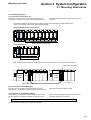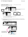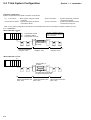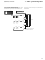
1
series
USER'S MANUAL
T-LINK MASTER MODULE
T-LINK INTERFACE MODULE
FEH204
Preface
This User’s Manual explains T-link master module, T-link
interface module and T-link specifications of MICREX-SX
series. Read this manual carefully to ensure correct
operation.
When using modules or peripheral devices, be sure to read
the corresponding user’s manuals listed below.
Title
Manual No.
Contents
User's Manual Instruction, MICREX-SX
series SPH/SPS
FEH200
Explains the memory, language and system definitions of the
MICREX-SX series.
User's Manual Hardware,
MICREX-SX series SPH
FEH201
Explains the system configuration, the specifications and
operations of modules in the MICREX-SX series.
User's Manual P/PE-link modules, MICREXSX series SPH
FEH203
Explains the communication specifications of P/PE-link, the
specifications and operations of the modules.
User's Manual D300win <Introduction>,
MICREX-SX series
FEH250
Explains the basic operations of D300win, the programming
and monitoring for MICREX-SX series.
User's Manual D300win <Reference>,
MICREX-SX series
FEH251
Explains the menu and icon of D300win and all of the
operations of D300win.
Notes
1. This manual may not be reproduced in whole or part in any form without prior written approval by the manufacturer.
2. The contents of this manual (including specifications) are subject to change without prior notice.
3. If you find any ambiguous or incorrect descriptions in this manual, please write them down (along with the manual No.
shown on the cover) and contact FUJI.
Safety Precautions
Be sure to read the “Safety Precautions” thoroughly before
using the module.
Here, the safety precaution items are classified into
“Warning” and “Caution.”
Warning : Incorrect handling of the device may result in death or serious injury.
Caution : Incorrect handling of the device may result in minor injury or physical damage.
Even some items indicated by “Caution” may also result in a
serious accident.
Both safety instruction categories provide important
information. Be sure to strictly observe these instructions.
Warning
◊ Never touch any part of charged circuits as terminals and exposed metal portion while the power is turned ON. It may result
in an electric shock to theoperator.
◊ Turn OFF the power before mounting, dismounting, wiring, maintaining or checking, otherwise, electric shock, erratic
operation or troubles might occur.
◊ Place the emergency stop circuit, interlock circuit or the like for safety outside the PC. A failure of PC might break or cause
problems to the machine.
◊ Do not connect in reverse polarity, charge (except rechargeable ones), disassemble, heat, throw in fire or short-circuit the
batteries, otherwise, they might burst or take fire.
◊ If batteries have any deformation, spilled fluids, or other abnormality, do not use them. The use of such batteries might cause
explosion or firing.
◊ Do not open the FG terminal with the LG-FG short circuited. (It must be grounded, otherwise it might cause electric shock.)
Safety Precautions
Caution
◊ Do not use one found damaged or deformed when unpacked, otherwise, failure or erratic operation might be caused.
◊ Do not shock the product by dropping or tipping it over, otherwise, it might be damaged or troubled.
◊ Follow the directions of the operating instructions when mounting the product. If mounting is improper, the product might
drop or develop problems or erratic operations.
◊ Use the rated voltage and current mentioned in the operating instructions and manual. Use beyond the rated values might
cause fire, erratic operation or failure.
◊ Operate (keep) in the environment specified in the operating instructions and manual. High temperature, high humidity,
condensation, dust, corrosive gases, oil, organic solvents, excessive vibration or shock might cause electric shock, fire,
erratic operation or failure.
◊ Select a wire size to suit the applied voltage and carrying current. Tighten the wire terminals to the specified torque.
Inappropriate wiring or tightening might cause fire, malfunction, failure, or might cause the product to drop from its
mounting.
◊ Contaminants, wiring chips, iron powder or other foreign matter must not enter the device when installing it, otherwise,
erratic operation or failure might occur.
◊ Connect the ground terminal to the ground, otherwise, an erratic operation might occur.
◊ Periodically make sure the terminal screws and mounting screws are securely tightened.
Operation at a loosened status might cause fire or erratic operation.
◊ Put the furnished connector covers on unused connectors, otherwise, failure or erratic operation might occur.
◊ Install the furnished terminal cover on the terminal block, otherwise, electric shock or fire might occur.
◊ Sufficiently make sure of safety before program change, forced output, starting, stopping or anything else during a run.
The wrong operation might break or cause machine problems.
◊ Engage the loader connector in a correct orientation, otherwise, an erratic operation might occur.
◊ Before touching the PC, discharge any static electricity that may have been collected on your body. To discharge it, touch
a grounded metallic object. Static electricity might cause erratic operation or failure of the module.
◊ Be sure to install the electrical wiring correctly and securely, observing the operating instructions and manual. Wrong or
loose wiring might cause fire, accidents, or failure.
◊ When disengaging the plug from the outlet, do not pull the cord, otherwiase, break of cable might cause fire or failure.
◊ Do not attempt to change system configurations (such as installing or removing I/O modules) while the power is ON,
otherwise, failure or erratic operation might occur.
◊ Do not attemp to repair the module by yourself -- contact your Fuji Electric agent. When replacing the batteries, correctly
and securely connect the battery connectors, otherwise, fire, accidents or failure might occure.
◊ To clean the module, turn power off and wipe the module with a cloth moistened with warm water. Do not use thinner or
other organic solvents, as the module surface might become deformed or discolored.
◊ Do not remodel or disassemble the product, otherwise, a failure might occur.
◊ Follow the regulations of industrial wastes when the device is to be discarded.
◊ The modules covered in these operating instructions have not been designed or manufactured for use in equipment or
systems which, in the event of failure, can lead to loss of human life.
◊ If you intend to use the modules covered in these operating instructions for special applications, such as for nuclear
energy control, aerospace, medical, or transportation, please consult your Fuji Electric agent.
◊ Be sure to provide protective measures when using the module covered in these operating instructions in equipment
which, in the event of failure, may lead to loss of human life or other grave results.
Revision
*Manual No. is shown on the cover.
Printed on
*Manual No.
Revision contents
Sep.1998
FEH204
First edition
Contents
Preface
Safety Precautions
Revision
Contents
page
Section 1 General ............................................................................................... 1-1
1-1 T-link System Configuration .................................................................................................................. 1-1
Section 2 Specifications .................................................................................... 2-1
2-1 Specifications .........................................................................................................................................2-1
2-2 T-link Communication Specifications ...................................................................................................2-2
2-2-1 Communication specifications ....................................................................................................................... 2-2
2-2-2 Basics of T-link transmission ......................................................................................................................... 2-2
2-2-3 Transmission types ........................................................................................................................................ 2-3
2-3 Cable ........................................................................................................................................................2-4
2-4 Names and Functions ............................................................................................................................2-5
2-4-1 NP1L-TL1 (T-link master module) .................................................................................................................. 2-5
2-4-2 NP1L-RT1 (T-link interface module) .............................................................................................................. 2-7
2-5 Dimensions .............................................................................................................................................2-9
Section 3 System Configuration ....................................................................... 3-1
3-1 Mounting Restrictions ...........................................................................................................................3-1
3-1-1 Mounting position ........................................................................................................................................... 3-1
3-1-2 Number of mountable modules ...................................................................................................................... 3-1
3-2 T-link System Configuration .................................................................................................................. 3-2
3-2-1 Basic system configuration ............................................................................................................................ 3-2
3-2-2 I/O address assignment ................................................................................................................................. 3-3
3-2-3 Communication system with other series using T-link slaves ....................................................................... 3-4
3-2-4 T-link system using the T-link electric repeater/converter ............................................................................. 3-5
3-2-5 System configuration using the T-link optical converter ................................................................................ 3-7
Section 4 System Definitions System Configuration ...................................... 4-1
4-1 System Configuration Definition ..........................................................................................................4-1
4-2 Fail-soft Setting ......................................................................................................................................4-7
4-3 Output Hold Definition ...........................................................................................................................4-9
Section 5 Wiring.................................................................................................. 5-1
5-1 Precautions .............................................................................................................................................5-1
5-2 T-link Wire Assembling ...........................................................................................................................5-2
Section 6 RAS ..................................................................................................... 6-1
6-1 System Memory ......................................................................................................................................6-1
Section 1 General
page
1-1 T-link System Configuration ................................................................................... 1-1
Section 1 General
1-1 T-link System Configuration
The T-link master module NP1L-TL1 is mounted on the
MICREX-SX series base board (connected to the SX bus).
This module controls one T-link system which is the Fuji
Electric-specific high-speed serial communication network.
Various types of T-link devices can be connected as shown
in the figure below.
SX bus
The SX bus transfers data between
the T-link and CPU.
T-link master module
NP1L-TL1
Power
supply
MICREX-SX
series base
board
CPU
0
T-link
High-speed remote I/O link
with 500kbps transfer rate.
Power
supply
T-link I/O
capsule
FALDIC
General-purpose
inverter
T-link I/O
group-type unit
Digital servo
T-link interface module NP1L-RT1
T-link converter
Mini T-link (up to 100m)
PK2
Bar code reader
• • •
Note: T-link devices that use conventional loader commands,
such as MICREX-F series loaders, FLEX-PC series
loaders, and POD, cannot be connected to NP1L-TL1.
Mini T-link I/O (up to 10 devices)
1-1
Section 2 Specifications
page
2-1 General Specifications ............................................................................................ 2-1
2-2 T-link Communication Specifications .................................................................... 2-2
2-2-1 Communication specifications ........................................................................................... 2-2
2-2-2 Basics of T-link transmission .............................................................................................. 2-2
(1) Initial transmission .............................................................................................................................. 2-2
(2) Normal transmission ........................................................................................................................... 2-2
(3) Transmission errors ............................................................................................................................ 2-2
2-2-3 Transmission types ............................................................................................................ 2-3
(1) I/O transmission .................................................................................................................................. 2-3
(2) Message transmission ........................................................................................................................ 2-3
2-3 Cable ......................................................................................................................... 2-4
2-4 Names and Functions .............................................................................................. 2-5
2-4-1 NP1L-TL1 (T-link master module) ...................................................................................... 2-5
(1) Names ................................................................................................................................................ 2-5
(2) Functions ............................................................................................................................................ 2-5
2-4-2 NP1L-RT1 (T-link interface module) .................................................................................. 2-7
(1) Names ................................................................................................................................................ 2-7
(2) Functions ............................................................................................................................................ 2-7
2-5 Dimensions ............................................................................................................... 2-9
General specifications
Section 2 Specifications
2-1 General Specifications
Item
Physical
environmental
conditions
Mechanical
service
conditions
Electrical
service
conditions
Specification
Operating ambient
temperature
0 to 55° C
Storage temperature
-25 to +70° C
Relative humidity
20 to 95%RH no condensation
(Transport condition: 5 to 95%RH no condensation)
Pollution degree
2
Corrosion immunity
Free from corrosive gases. Not stained with organic solvents.
Operating altitude
2000m or less above sea level (Transport condition: 70kPa or more)
Vibration
Half amplitude: 0.15mm, Constant acceleration: 19.6m/s2,
Two hours for each of three mutually perpendicular axes, total six hours.
Shock
Acceleration peak: 147m/s2
Three times for each of three mutually perpendicular axes.
Noise immunity
1.5kV, rise time 1ns, pulse width 1µs (noise simulator)
Electrostatic
discharge
Contact discharge: ± 8kV
Aerial discharge: ± 15kV
Radioelectromagnetic 10V/m (80MHz to 1000MHz)
field
Construction
Panel-mounted type
Cooling
Air cooling
Isolation method
Photocoupler
Dielectric strength
445V AC 1 minute (between connector pins and frame ground)
Insulation resistance
10MΩ or more with 500V DC megger (between connector pins and frame ground)
Internal current consumption
NP1L-TL1: 24V DC, 140mA or less, NP1L-RT1: 24V DC, 140mA or less
Mass
NP1L-TL1: Approx. 200g, NP1L-RT1: Approx. 200g
Dimensions
Described in 2-5
2-1
2-2 T-link Communication Specifications
2-2-1 Communication specifications
Item
Specification
No. of connectable
devices
T-link system slave stations per master module (one T-link system ): Max. 32
No. of I/O points
Digital I/O conversion (per T-link system): Max. 128 words (2,048 points)
Transmission line
format
Bus configuration (multi-drop)
Optical loop connection through optical converters on each bus (Loops can be duplicated.)
Transmission line
Bus transmission line: Twisted pair cable (1 pair)
Total length: Max. 1km
Optical transmission line: SI/GI quartz fiber cable (length between optical converters: Max. 1km/3km)
Transmission method Half-duplex, serial transmission
Data exchange
method
1 : N (polling/selecting) method
Transmission speed
500kbps
Effective transmission 7kbytes/sec. (10ms/512 digital points)
speed
Modulation method
PDM (Pulse Duration Modulation)
Error check
FCS (frame check sequence)
Duplication of
transmission line
Optical converters enable duplication of optical transmission lines.
2-2-2 Basics of T-link transmission
Data transmission on the T-link uses the polling/selecting
method. In the polling/selecting method, the master module
first talks to a slave station with the specified station number,
then the slave station responds to it. This section describes
the basics of the data transmission.
(1) Initial transmission
When the power is turned on, the master module performs
initial transmission before starting to operate. That is, the
master module checks the I/O configuration, and the
address of (the station number) slave stations connected to
the T-link when the power is turned on. The master module
checks from station 0 to station 99 in sequence. After
checking them completely, the master module starts to
operate. When the results of the check are different from
settings in the system configuration definition, the “SER”
(setting error) lamp lights indicating a configuration error
(fatal fault).
(3) Transmission errors
When an error occurs during T-link transmission, data
transmission fails. The master module will retry
transmission. An error may occur due to power interruption
of a slave station, disconnection of a T-link cable, noise, or
malfunction of T-link transmission elements in the master
module or slave station. If communication returns to a
normal state after transmission retry, T-link transmission
continues and the master module continues its operation.
If communication still fails after transmission retry has been
repeated three times for the same slave station, the master
module regards it as a fatal fault and stops operation. In this
case, the master module cannot return to operation until the
cause of the fault is removed and the master module power
supply is reset. However, if fail-soft operation is specified,
the CPU module regards it as a nonfatal fault and continues
operation.
(2) Normal transmission
After initial transmission, the T-link enters normal
transmission mode. In this mode, CPU exchanges I/O data
with slave stations that have been already checked for their
connections with the T-link in initial transmission, in
ascending order by their numbers. When CPU exchanges
data with the final station, CPU repeats the data exchange
with them. This cycle is called a “transmission cycle.”
2-2
2-2 T-link Communication Specifications
2-2-3 Transmission types
The T-link handles I/O transmission and message
transmission.
(1) I/O transmission
I/O transmission is a high-speed communication method
enabling transmission of signals from distributed I/O devices
to the PC. On the T-link data refresh is usually performed
Slave
station B
Slave
station A
Master
Slave station
Output
Output
every 10ms. However, if one T-link system is connected to a
large number of I/O devices or there are a large number of
occupied words, the refresh cycle may exceed 10ms.
Input
Slave
station C
Output
Output
Input
Slave
station A
Input
Input
Transmission cycle: 10ms
(2) Message transmission
Message transmission is a way to transfer a large amount of
data between the CPU and slave stations. The T-link takes
several I/O transmission cycles from the beginning of a
request for a message to its completion (until data delivery is
completed), thus message transmission is slower than I/O
transmission. Also, the master module handles message
transmission for one station at a time. Therefore, when
many devices that use message transmission (such as
POD) are connected to one master module, the transmission
rate becomes slower in proportion to the number of
connected devices.
<Example of message transmission>
Message request
Message processing
Message completion
Master
Slave station
Transmission cycle: 10ms
2-3
2-3 Cable
Cable
Cables that meet the following specifications should be used
for the T-link cables.
Maker
KPEV-SB
The Furukawa Electric Co., Ltd.,
Japan
Daiden Co., Ltd., Japan
Taiyo Electric Wire & Cable Co., Ltd.,
Japan
Maximum length
Cable type
T-KPEV-SB
T-link
0.75mm2 x 1 pair
Mini T-link
700m
100m
2
1000m
100m
2
1.25mm x 1 pair
0.5mm x 1 pair
700m
100m
RMEV-SB
0.5mm2 x 1 pair
290m
100m
Cable used for robot
RVV-SB
0.5mm2 x 1 pair
200m
100m
Cable used for robot
250m
100m
0.5mm x 1 pair
700m
100m
Fujikura Cable Works Co., Ltd.
0.5mm2 x 1 pair
700m
100m
TTYCS-1
x 1 pair
100m
100m
250V-TTYCYS
x 1 pair
50m
50m
KPEV-SB
0.5mm2 x 1 pair
700m
100m
KNPEV-SB
0.5mm2 x 1 pair
700m
100m
Nippon Cables Co., Ltd.
IPEV
2
Note: The maximum length values in the above table are confirmed by Fuji.
2-4
Twisted pair cable
KPEV-SB
Sumitomo Electric Industries Co., Ltd., TWIN-100
Japan
DPEV-SB
Hien Denko Co., Ltd.
Remarks
Cable used for vessel
Names and functions
2-4 Names and Functions
2-4-1 NP1L-TL1 (T-link master module)
(1) Names
Status indication LED
ONL
T/R
ERR
TER
SER
T-link station No. selection switch
4 5 6
9 0 1
2 3
Nameplate (on the right side)
7 8
2 3
4 5 6
9 0 1
T-link connector
7 8
(2) Functions
1) Status indication LED
This LED indicates the NP1L-TL1 operation status.
ONL
T/R
ERR
TER
SER
Symbol Color
Description:
ONL
Green
Turns on when the master module is operating normally (when the SX bus
operates normally).
ERR
Red
Turns on when an error has occurred in the master module or SX bus.
T/R
Green
Turns on when T-link data is being transferred or recieved.
TER
Red
Turns on when a nonfatal fault has occurred in a unit on the T-link,
a registered station has become disconnected, or a transmission error has
occurred.
SER
Red
Turns on when there is an error in the system configuration.
<Example of LED status indications>
Common
indicators
Individual indicators
ONL
T/R
ERR
Module status
SER
TER
Blinks
—
—
—
—
The module is waiting for initialization of the SX bus. (common for all stations)
On
—
Blinks
—
—
The module is operating normally.
On
—
Blinks
—
*
(*: The transmission error LED indicator blinks sometimes, but the module can
continue operation.)
—
On
—
—
—
The local module has a hardware fault or SX bus error. (module fatal fault)
On
—
Blinks
—
—
Remote I/O has a fault. (remote I/O fatal fault)
On
—
Blinks
On
—
Remote I/O configuration has a fault. (remote I/O nonfatal fault)
—
—
—
—
—
24V DC power is not connected.
Note: “—” indicates that the LED is OFF.
2-5
2-4 Names and Functions
2) T-link station No. selection switch
Not used on this module (NP1L-TL1).
3) T-link connector
This connector is used to connect the T-link connector. The
tightening torque for the connector fixing screw should be
between 0.9 to 1.0N•m. For assembly of the T-link connector,
refer to Section 5-2.
2-6
Names and functions
4) Nameplate
The type, production date, and serial number are printed on
the right side of the module.
Names and functions
2-4 Names and Functions
2-4-2 NP1L-RT1 (T-link interface module)
(1) Names
Status indication LED
ONL
T/R
ERR
TER
SER
T-link station No. selection switch
2 3
9
5 6
0 1
4
X10
Nameplate (on the right side)
7 8
2 3
9
5 6
0 1
4
T-link connector
X1
7 8
(2) Functions
1) Status indication LED
This LED indicates the NP1L-RT1 operation status.
ONL
T/R
ERR
TER
Symbol Color Description:
SER
ONL
Green
Turns on when the interface module is operating normally.
ERR
Red
Turns on when an error has occurred in the interface module or a unit on
the T-link.
T/R
Green
Turns on when T-link data is being transferred or received.
TER
Red
Turns on when a nonfatal fault has occurred in a unit on the T-link, or a
station registered in the configuration cannot be found.
SER
Red
Turns on when there is an error in a system definition.
<Example of LED status indications>
Common indicators Individual indicators
ONL
ERR
T/R
SER
Module status
TER
—
—
—
—
—
The interface module has not been initialized.
On
—
Blinks
—
—
The module is operating normally.
On
—
Blinks
On
*
A nonfatal fault has occurred.
—
On
—
—
—
A fatal fault has occurred.
On
—
On
—
On
A transmission error has been detected.
—
On
—
On
—
There is a setting error (such as a station number change during
transmission).
Note: 1) “—” indicates that the LED is OFF.
2) When I/O transmission is not started, ONL is not ON.
2-7
2-4 Names and Functions
2) T-link station No. selection switch
This switch is used to specify the T-link station number.
Range: 00 to 99
2 3
9
5 6
0 1
4
PH
x 10
PL
x1
7 8
2 3
9
5 6
0 1
4
7 8
2-8
Names and functions
3) T-link connector
This connector is used to connect the T-link connector. The
tightening torque for the connector fixing screw must be
between 0.9 to 1.0N•m. For assembly of the T-link
connector, refer to Section 5-2.
4) Nameplate
The type, production date, and serial number are printed on
the right side of the module.
Dimensions
2-5 Dimensions
The dimensions of NP1L-TL1 and NP1L-RT1 are identical.
(44)
90
105
34.8
Note: When the module is used as the end terminal of the T-link,
a T-link terminating resistor must be attached.
When the resistor is attached, an approximately 22mm to
24mm protrusion is added.
2-9
Section 3 System Configuration
page
3-1 Mounting Restrictions ............................................................................................. 3-1
3-1-1 Mounting position ............................................................................................................... 3-1
(1) T-link master module NP1L-TL1 ......................................................................................................... 3-1
(2) T-link interface module NP1L-RT1 ...................................................................................................... 3-1
3-1-2 Number of mountable modules .......................................................................................... 3-1
3-2 T-link System Configuration ................................................................................... 3-2
3-2-1 Basic system configuration ................................................................................................ 3-2
3-2-2 I/O address assignment ..................................................................................................... 3-3
3-2-3 Communication system with other series using T-link slaves ............................................ 3-4
3-2-4 T-link system using the T-link electric repeater/converter .................................................. 3-5
(1) Overview of the T-link Electric Repeater (FRC200A-C10) .................................................................. 3-5
(2) Overview of the T-link converter (FRC100A-G02) .............................................................................. 3-5
(3) Notes on connecting T-link electric repeaters and T-link converters ................................................... 3-5
(4) Examples of system configurations .................................................................................................... 3-6
3-2-5 System configuration using the T-link optical converter ..................................................... 3-7
(1) Overview of the T-link optical converter .............................................................................................. 3-7
(2) System configuration .......................................................................................................................... 3-8
Mounting restrictions
Section 3 System Configuration
3-1 Mounting Restrictions
3-1-1 Mounting position
(1) T-link master module NP1L-TL1
The NP1L-TL1 is the remote I/O master module which is
connected to the SX bus. The figure below shows the slots
on the base board to which a master module can be
mounted.
The master module can be mounted on any slot except for the power supply module mounting slots
( the first and second slots from the left on the base board).
<Base board without 6-slot base board>
Master module mountable slots
<6-slot base board>
Master module mountable slots
Note: A T-link master module can not be mounted on the base board of a T-link or JPCN-1 slave station.
T-link interface module
I/O
Power
supply
I/O
I/O
I/O
CPU
T-link master module
(2) T-link interface module NP1L-RT1
The NP1L-RT1 is mounted on the base board of a T-link
slave station. The interface module must be mounted on the
Power
supply
x
right side of the power supply module.
3-1-2 Number of mountable modules
Up to 8 NP1L-TL1 modules can be mounted for one SX bus
system. However, if another I/O master module (such as a
JPCN-1 master module) is mounted, the number of
mountable modules is a total of 8.
(Number of mountable T-link master modules) + (Number of mountable other I/O master modules) ≤ 8
A base board can contain only one NP1L-RT1 module.
3-1
Basic system
3-2 T-link System Configuration
3-2-1 Basic system configuration
system configuration to be constructed.
Connecting one NP1L-TL1 master module with the MICREXSX series SX bus (on the base board) enables one T-link
<Example of system configuration>
NP1L-TL1
I/O
Power
supply
SX bus
terminating
plug
I/O
I/O
I/O
CPU
* Connect the T-link terminating resistor (100‰)
to the end of the T-link.
NP1L-RT1
*
Power
supply
*
T-link devices can be connected. (Note 2)
The T-link interface module (NP1L-RT1) enables MICREX-SX series
SPH I/O modules to be used as T-link devices.
Note: 1) The allowable distance depends on the type of the cable used. For the details, refer to “2-3 Cable Specifications.”
2) Devices that use different loader commands such as MICREX-F series loaders, FLEX-PC series loaders, and POD
cannot be connected.
3) The configuration shown below is not possible.
NP1L-TL1
I/O
Power
supply
I/O
I/O
I/O
I/O
I/O
I/O
CPU
T-link
I/O
I/O
I/O
I/O
I/O
I/O
Power
supply
NP1L-RT1
* Connecting a base board in
a T-link slave station with another
base board using an SX bus
connection cable is not allowed.
3-2
I/O
Power
supply
I/O address assignment
3-2 T-link System Configuration
3-2-2 I/O address assignment
I/O address assignment is shown below.
<Example of system configuration>
I/O address assignment on the SX bus.
Power
supply
CPU
0
TL1
I/O
16points
Input
“254”
I/O
32points 16points
Input Output
“1”
“2”
“3”
“4”
%IX 1.0.0
to
%IX1.0.15
%IX 3.0.0
to
%IX3.0.15
%IX 3.1.0
to
%IX3.1.15
%QX 4.0.0
to
%QX4.0.15
SX bus station No.
T-link group-type
I/O device
1
*
2
3
4
FTL
16points 32points 16points 32points
Input
Input Output Output
Power
supply
“05”
“05”
“06”
“08”
I/O
number
16points
Output
16points
Input
“09”
“11”
T-link station No.
“12”
T-link station No.
I/O address assignment on the T-link
* indicates a terminating resistance position.
%IX 2.5.0.0
to
%IX2.5.0.15
%IX 2.6.0.0
to
%IX2.6.0.15
%IX 2.6.1.0
to
%IX2.6.1.15
%QX 2.8.0.0
to
%QX2.8.0.15
%QX 2.9.0.0
to
%QX2.9.0.15
%QX 2.9.1.0
to
%QX2.9.1.15
%IX 2.11.0.0 to
%IX2.11.0.15
%QX 2.12.0.0 to
%QX2.12.0.15
<Addressing modes>
In MICREX-SX series, the I/O addresses on the SX bus are
assigned to the same I/O area as the I/O addresses on the T-link.
Period
Period
Prefix
SX bus station No.
T-link station No.
%IX(bit), %IW(word), %ID(double word)
%QX(bit), %QW(word), %QD(double word)
<Address number assignments>
The address of each I/O module mounted on the T-link
group type I/O device needs the T-link station number and
the word number which indicates the order in the device.
Period
Word No.
Bit address
From 00 to 99
Example: In the sample system configuration shown above ,
the address of the bit 32 position of the 32-point
input module ( the module at far right) on the
T-link group type I/O device would be expressed
as follows:
%IX2.1.1.15
SX bus station number
Bit address (0 to 15)
Word number ( For a 32-point module, both words 0 and 1 exist.
For a 16-point module, word 0 exists.)
T-link station number
3-3
T-link slave system
3-2 T-link System Configuration
3-2-3 Communication system with other series
using T-link slaves
MICREX-SX series SPH CPUs and MICREX-F series or
FLEX-PC series CPUs.
Using MICREX-F series or FLEX-PC series T-link slave
modules, data can be transferred through T-link between
<Example of connection to MICREX-F55 series>
The MICREX-SX series CPU is the master, and the
MICREX-F55 series CPU is a slave.
MICREX-F55 series T-link
slave card
16 points input
“254”
SPH
Power
supply
“1”
“2”
“3”
“4”
“5”
I/O
I/O
I/O
I/O
MICREX-F55
“10”
CPU
WBO
T-link
Slave card setting:
Input: 4 words
Output: 4 words
T-link station number: 10
T-link master module
<Assignment of I/O addresses>
Slave CPU side
Master CPU side
WB1
%IW1.10.0 (%IX1.10.0.0~15)
Input
Output
3-4
%IW1.10.1 (%IX1.10.1.0~15)
T-link
WB2
%IW1.10.2 (%IX1.10.2.0~15)
WB3
%IW1.10.3 (%IX1.10.3.0~15)
WB4
%QW1.10.4 (%QX1.10.4.0~15)
WB5
%QW1.10.5 (%QX1.10.5.0~15)
WB6
%QW1.10.6 (%QX1.10.6.0~15)
WB7
%QW1.10.7 (%QX1.10.7.0~15)
WB8
Electric repeater/converter
3-2 T-link System Configuration
3-2-4 T-link system using the T-link electric
repeater/converter
(1) Overview of the T-link Electric Repeater (FRC200AC10)
The FRC200A, with the functions listed below, allows
flexible T-link network configurations.
• Extension of the T-link transmission distance
Two repeaters can be used for one T-link system. The
transmission distance can be extended up to 3 km.
• Branching of transmission line
T-branches can be used.
• Connection with mini T-link
The repeater supports mini T-link. The repeater has four
pairs of terminals for connecting cables. (Terminal
names: T-link 1, T-link 2, T-link 3, mini T-link)
Either the T-link 3 connectors or mini T-link connectors
can be used by setting a switch.
Note: 1) When the FRC200A repeaters are located at each end of the T-link, or for unused link connectors, connect the
supplied terminating resistor (100Ω/1 W). For the T-link 3 connectors and mini T-link connectors, it is not
necessary to connect the terminating resistor to the connectors that are not selected by the switch.
2) For the T-link 3 connectors and mini T-link connectors, signals are transmitted to the connectors selected by the
switch.
(2) Overview of the T-link converter (FRC100A-G02)
The FRC100A converts T-link signals to mini T-link signals
(and vice versa) to support connections with various T-link
I/O devices or mini T-link I/O devices.
Note: For terminating of the T-link or mini T-link transmission lines, connect the supplied terminating resistor (100Ω/1 W).
(3) Notes on connecting T-link electric repeaters and
T-link converters
Note the restrictions described below for T-link (mini T-link)
system construction.
TL1
TL1: T-link master module
TK : T-link slave station
*
Symbol * indicates
a place to which a
terminating resistor
is to be connected.
*
TK
Repeater/
Converter
For mini T-link system,
up to 10 stations (100m)
*
TK
*
TK
TK
TK
Up to 32 stations (except repeaters and converters) for one T-link system
<Number of repeaters and converters usable for one T-link system>
Serial connection
Parallel connection
T-link converter
(FRC100A-G02)
1
2
T-link electric repeater
(FRC200A-C10)
2
2
3-5
Electric repeater/converter
3-2 T-link System Configuration
(4) Examples of system configurations
1) One repeater/converter in series
TL1
TL1 : T-link master module
TK : T-link slave station
*
*
TK
Repeater/
Converter
The symbol * indicates a place
to which a terminating resistor
is to be connected.
*
*
TK
TK
TK
2) Two repeaters in series
This configuration is allowed only for the T-link electric
repeater (FRC200A-C10).
TL1
*
*
TK
Repeater
*
TK
*
TK
Repeater
*
*
TK
TK
TK
3) Repeaters/converters in parallel
TL1
*
Repeater/
Converter
TK
*
*
TK
TK
*
Repeater/
Converter
TK
*
*
TK
TK
4) Repeaters/converters in series and parallel
TL1
*
*
TK
Repeater
*
TK
*
TK
*
Repeater/
Converter
*
*
TK
3-6
TK
TK
Repeater
*
*
TK
TK
Optical converter
3-2 T-link System Configuration
3-2-5 System configuration using the T-link optical
converter
provide transmission lines suitable for use with noisegenerating devices.
The allowable length of the T-link can be extended using
optical transmission lines. Optical transmission lines are
minimally affected by noise, thus optical transmission lines
(1) Overview of the T-link optical converter
There are two types of T-link optical converter available:
simple type FNC120A and high performance type FNC130A.
POWER1
POWER2
STATUS1
STATUS2
STATUS3
POWER1
POWER2
STATUS1
STATUS2
STATUS3
Optical transmission
line interface (1)
Optical transmission
line interfaces (2)
Electric transmission
line interface (1)
FNC120A
Electric transmission
line interface (1)
FNC130A
<Communication specifications>
Item
Specification
Transmission speed
Electric
Optical
Cable
Total length
500kbps
Twisted pair cable (shielded)
Max. 1km
Cable
SI multi-component glass fiber
Core/clad diameter: 200µm/250µm
GI quartz fiber
Core/clad diameter: 50µm/125µm
Total length
Max. 1km
Max. 1km
<Optical adapter specifications>
Type
Applicable converter
Applicable fiber
Optical connector
FTC130T
FNC120A
FNC130A
SI multi-component glass
fiber, 200/250µm
F 06/08 (JIS C 5975, 8)
FTC132S
GI quartz fiber,
50/125µm
Note: For T-link optical converter specification details (FNC120Arefer to the operating instructions (INA-F7465).
, FNC-130A-
) and operation of the converters,
3-7
Optical 1 : 1 connection
3-2 T-link System Configuration
(2) System configuration
System configurations with optical converters are as follows:
1) 1 : 1 connection...........Basic system using two optical
converters.
2) Cascade connection....System with optical converters
connected in series.
3) Star connection...........System with optical converters
connected in parallel.
4) Loop connection..........System with optical converters
connected to a loop line.
Note: In any system configuration the number of slave stations that can be connected to a master module is up to 32.
1) 1 : 1 connection
<When FNC120A is used>
TL1
TL1 : T-link master module
TK : T-link slave station
OC : T-link optical converter
*
*
TK
OC
Symbol * indicates a place to
which a terminating resistor is
to be connected.
OC
*
*
Optical cable (1)
(2 wires)
TK
TK
Electric transmission
line (Max. 1km)
Optical transmission
line(Max. 1km)
Electric transmission
line (Max. 1km)
TK
<When FNC130A is used>
TL1
Optical cable (1)
(2 wires)
*
*
TK
OC
OC
*
*
TK
TK
TK
The FNC130A can duplicate
an optical transmission line.
Electric transmission line Optical transmission line
(Max. 1km)
(Max. 1km)
3-8
Electric transmission line
(Max. 1km)
Optical cascade connection
3-2 T-link System Configuration
2) Cascade connection
<When FNC120A is used>
This system connects electrical transmission lines and
optical transmission lines alternately in series. This system
can contain up to 16 optical converters.
TL1
Symbol *indicates a place
to which a terminating resistor
is to be connected.
Optical cable (1)
(2 wires)
*
*
OC
OC
*
*
TK
OC
*
OC
*
OC
OC
TK
TK
Electric transmission
line (Max. 1km)
*
Optical transmission
line (Max. 1km)
Electric transmission
line (Max. 1km)
Optical transmission
Optical transmission
line (Max. 1km)
line (Max. 1km)
Electric transmission
line (Max. 1km)
As illustrated above, the optical transmission line can be
extended up to 8km and the electric transmission line can be
extended up to 9 km with 16 optical converters by alternately
connecting electric transmission lines and optical
transmission lines together. The total extendable line length
is 17km.
<When FNC130A is used>
This system connects electric transmission lines and optical
transmission lines in series. However, this system can be
established by connecting only optical transmission lines.
This system can contain up to 16 optical converters.
TL1
Optical cable (1)
(2 wires)
*
*
OC
OC
OC
TK
*
TK
*
TK
*
TK
Electric transmission
Optical transmission
line (Max. 1km)
line (Max. 1km)
*
TK
Electric transmission
line (Max. 1km)
Electric transmission
line (Max. 1km)
T-link devices can be connected to
optical converters on optical transmission
lines.
3-9
Optical star connection
3-2 T-link System Configuration
3) Star connection
A star T-link system can be constructed by connecting optical
converters to electric transmission lines (up to 8 routes).
<When FNC120A is used>
TL1
Symbol * indicates a place
to which a terminating
resistor is to be connected.
*
For two electric
transmission line
routes, up to 1km
OC
OC
*
Up to 8 routes
*
For three or more
electric transmission
line routes,
up to 500m
TK
TK
TK
OC
OC
*
*
*
TK
Optical transmission line
(Max. 1km)
TK
TK
Electric transmission line (Max. 1km)
<When FNC130A is used>
TL1
*
For two electric
transmission line
routes, up to 1km
OC
*
*
Up to 8 routes
For three or more
electric transmission
line routes,
up to 500m
Optical cable
OC
TK
TK
The FNC130A can duplicate
an optical transmission line.
OC
OC
*
*
*
TK
Optical transmission
line (Max. 1km)
3-10
TK
TK
Electric transmission line (Max. 1km)
TK
Optical loop connection
3-2 T-link System Configuration
4) Loop connection (FNC120A or FNC130A)
The loop connection efficiently implements redundant optical
transmission lines. By looping the optical transmission lines,
transmission continues even if a part of the optical cable line
is disconnected.
TL1
Symbol * indicates a place
to which a terminating
resistor is to be connected.
OC
*
*
TK
TK
Up to 1km
OC
Up to 1km
*
*
TK
TK
Up to 1km
OC
*
*
TK
TK
Up to 3 optical converters can be
connected in an optical loop.
Electric transmission line (Max. 1km)
3-11
Section 4 System Definitions
page
4-1 System Configuration Definition ............................................................................ 4-1
4-2 Fail-soft Setting ........................................................................................................ 4-7
4-3 Output Hold Definition ............................................................................................. 4-9
System configuration
Section 4 System Definitions
4-1 System Configuration Definition
To construct a T-link system in the MICREX-SX series SPH,
the system definitions listed below are required.
• System configuration definition (always needed)
• Fail-soft setting
• Output hold definition
Register modules to be used such as CPU modules, T-link
master modules, and T-link interface modules, or T-link
capsules with “System_Definition” in the project tree.
<Example of system configuration>
T-link master module
I/O
Power
supply
I/O
I/O
I/O
CPU
I/O
I/O
I/O
T-link capsule
Station No. : 10
Power
supply
T-link interface module
Station number: 00
<System configuration definition tree screen>
The figure below shows the system configuration definition
tree described above.
Only I/O modules are registered
on the T-link interface.
Base boards and power supply
modules are not registered.
4-1
System configuration
4-1 System Configuration Definition
<Setting procedure>
1) Double-click the [System_Definition] icon in the
project tree with the left button. The system
configuration window is displayed. As shown in
the figure below, the window initially displays the
11-slot base board with the registered power
supply module and CPU module.
[Insert] button
To change the base board, select base board
and left-click the [property] button.
The module property dialog box is displayed.
Select the desired base
board in this box.
2) Register the T-link master module Left-click the
[Insert] button on the system configuration
registration window. The “Module insert” dialog
box is displayed.
Set the remote I/O master module
line number from 0 to 7.
Select the I/O master
I/O master group
Select the T-link master,
then left-click the OK
button.
4-2
System configuration
4-1 System Configuration Definition
3) Register the T-link device (T-link interface module)
to be connected to the T-link master module.
[Insert] button
Left-click the [Insert] button
while selecting the T-link master.
The slave group contains
these three types.
Select “Slave.”
To connect a MICREX-SX SPH T-link interface
module, select “T-link i/f unit (RT1).” To connect
a conventional MICREX-F series T-link interface
module, select “T-link i/f unit (FTL).” To connect a
T-link I/O capsule, select “T-link capsule.”
4-3
4-1 System Configuration Definition
System configuration
4) Register the I/O module to be mounted on the base
board which contains the T-link interface
(NP1L-RT1).
Left-click the [Insert] button
while selecting the T-link interface.
Select “Remote I/O” for the I/O module
on the T-link interface (RT1).
4-4
System configuration
4-1 System Configuration Definition
5) Register the MICREX-F series T-link I/O capsule.
Left-click the [Insert] button
while selecting the T-link master.
Set the T-link
station number.
Select “T-link capsule.”
Select “Slave.”
Left-click the [Parameter...] button.
The “T-link capsule parameter setting” dialog box is
displayed. Set the number of occupied words.
Left-click [OK].
After determining the setting,
left-click [OK]. The “Module
insertion” dialog box appears.
4-5
System configuration
4-1 System Configuration Definition
6) Register the I/O group for the module registered in
the configuration. Left-click the [I/O Group Setting] tab
in the “CPU parameter” dialog box.
When only one CPU module is used,
clicking this button automatically
registers all modules/capsules
contained in the “I/O list.”
After determining the setting,
left-click the [OK] button.
4-6
Fail-soft
“Fail-soft operation” means to have normal modules/
capsules continue their operation even if an error occurs in
an I/O module/capsule on the SX bus or T-link.
4-2 Fail-soft Setting
Set “Fail-soft operation” using the “Fail-soft setting” in the
CPU module parameter.
<Setting procedure>
1) Select the CPU module. The fail-soft setting in the
“CPU parameter” dialog box is displayed.
Select CPU module
and left-click the
[property] button.
The “Module property” dialog box is displayed.
Left-click this button.
Key-point
For modules on the SX bus, the CPU does not start operation if the modules registered on the system configuration are not
started up. However, specifying the fail-soft setting for devices such as remote I/O modules on the T-link enables the CPU to
start operation in a “nonfatal fault” state even if remote I/O modules have not been started up. After the remote I/O modules
start up, the “nonfatal fault” state will change to “normal.”
4-7
Fail-soft
4-2 Fail-soft setting
2) Select the module/capsuls to specify fail-soft setting
for, then register them.
Select the modules/capsules,
left-click this button to
register them.
After registration, left-click
this button.
4-8
Output hold
To hold the state which existed immediately before a system
fault that stops CPU module operation, or to hold the output
immediately before the CPU module stops, use the output
4-3 Output Hold Definition
hold facility.
Set the “Output hold” setting using the “Individual output hold
station definition” parameter on the T-link master module.
<Setting procedure>
1) Select the T-link master module. “The T-link master
parameter setting” is displayed.
Select T-link master module and
left-click the [property] button.
The “Module property” dialog box is displayed.
Left-click this button.
4-9
4-3 Output Hold Definition
Output hold
2) Left-click the station numbers of the T-link devices
to be registered with the output hold.
Only the station numbers
registered with the
system configuration can
be selected.
After setting the stations, left-click this button.
4-10
Section 5 Wiring
page
5-1 Precautions .............................................................................................................. 5-1
5-2 T-link Wire Assembling ........................................................................................... 5-2
Section 5 Wiring
5-1 Precautions
(1) Before removing the connector, remove the fixing
screws.
(2) T-link cables must be isolated from high-voltage
cables and power cables as far as possible. T-link
cables must not be run parallel with those cables.
(3) These cables should be installed as shown in the
following figure. Shielding cables should be used.
Communication cables
1)
300mm
or more
Lower power cables
2)
1) RS-232C, RS-485
communication cables
2) Input/output circuit. Power
supply circuit for PC.
3) Control circuit
4) Power circuit
300mm
or more
Control cables
3)
300mm
or more
Power cables
4)
Metal plate
Grounding
(Grounding resistance of 100‰ or less)
Communication cables
1)
Lower power cables
2)
Control cables
Power cables
3)
200mm
or more
4)
Grounding
(Grounding resistance of 100‰ or less)
5-1
5-2 T-link Wire Assembling
Process the end of a twisted pair cable as shown below.
1) Remove a part of the sheath
and internal insulation.
2) Attach crimp terminals.
Apply the insulation tube before caulking the terminal.
Note:If wires are connected directly to the terminal
block without using crimp terminals,
connection failure may result and T-link
transmission errors may occur. Therefore, crimp
terminals must be used.
9
Approx. 40mm
The followings are recommended.
When two T-link cables are to be
connected to one terminal block, each
pair of wires can be connected to one
crimp terminal for convenience.
Maker
Type
JST(Nichiatsu)
Toei
2-M3
2-3.5, 2-4S
3) Assembling
Tightening torgue : 0.3 to 0.4N•m
T-link terminating resistance
Note: Connect T-link terminating resistances
to both ends of the T-link.
SD
5-2
T1
T2
Section 6 RAS
page
6-1 System Memory ....................................................................................................... 6-1
(1) I/O module fault (%MX10.2.5) ............................................................................................................ 6-1
(2) Remote I/O master initialization error (%MX10.25.0 to %10.25.7) ..................................................... 6-1
(3) Remote I/O master-I/O module configuration/fault (%MW10.128 to %MW10.255) ............................ 6-2
Section 6 RAS
6-1 System Memory
The system memory area in the CPU module contains flags
for remote I/O masters.
(1) I/O module fault (%MX10.2.5)
When an I/O module or remote I/O module on the SX bus
that has been registered with an “I/O group” in the CPU
module, but not registered for the fail-soft setting, has a fault,
the CPU module stops its operation.
(2) Remote I/O master initialization error
(%MX10.25.0 to %10.25.7)
When an error occurs during initialization of a T-link
master module, a corresponding bit is turned on.
%MX10.25.0
Initialization error of remote I/O master 0
%MX10.25.1
Initialization error of remote I/O master 1
%MX10.25.2
Initialization error of remote I/O master 2
%MX10.25.3
Initialization error of remote I/O master 3
%MX10.25.4
Initialization error of remote I/O master 4
%MX10.25.5
Initialization error of remote I/O master 5
%MX10.25.6
Initialization error of remote I/O master 6
%MX10.25.7
Initialization error of remote I/O master 7
Note: Specify remote I/O master numbers using the “Insert module” dialog box or “Line number (R)” in the “Module property”
dialog box.
For example, specifying “0” for a line number sets the T-link
master module “Remote I/O master 0.”
6-1
6-1 System Memory
(3) Remote I/O master-I/O module configuration/fault
(%MW10.128 to %MW10.255)
6-2
%MW10.128
|
%MW10.135
Remote I/O master 0
I/O module configuration
%MW10.136
|
%MW10.143
Remote I/O master 0
I/O module fault
%MW10.144
|
%MW10.151
Remote I/O master 1
I/O module configuration
%MW10.152
|
%MW10.159
Remote I/O master 1
I/O module fault
%MW10.160
|
%MW10.167
Remote I/O master 2
I/O module configuration
%MW10.168
|
%MW10.175
Remote I/O master 2
I/O module fault
%MW10.176
|
%MW10.183
Remote I/O master 3
I/O module configuration
%MW10.184
|
%MW10.191
Remote I/O master 3
I/O module fault
%MW10.192
|
%MW10.199
Remote I/O master 4
I/O module configuration
%MW10.200
|
%MW10.207
Remote I/O master 4
I/O module fault
%MW10.208
|
%MW10.215
Remote I/O master 5
I/O module configuration
%MW10.216
|
%MW10.223
Remote I/O master 5
I/O module fault
%MW10.224
|
%MW10.231
Remote I/O master 6
I/O module configuration
%MW10.232
|
%MW10.239
Remote I/O master 6
I/O module fault
%MW10.240
|
%MW10.247
Remote I/O master 7
I/O module configuration
%MW10.248
|
%MW10.255
Remote I/O master 7
I/O module fault
Remote I/O master-I/O module configuration
When T-link devices connected with a T-link master are
normal or in a fault state, flags for corresponding T-link
station numbers are turned on.
Remote I/O master-I/O module fault
When T-link devices connected with a T-link master are in a
fatal or nonfatal fault state, flags for corresponding T-link
station numbers are turned on.
6-1 System Memory
<Flag assignment>
The following tables show an example of flag assignment
using the remote I/O master-I/O module configuration fault
(%MW10.128 to %MW10.143). Assignment for remote I/O
masters 1 to 7 are handled in the same manner.
<Configuration information>
Word address
15
14
13
12
11
10
9
8
7
6
5
4
3
2
1
0
%MW10.128
15
14
13
12
11
10
9
8
7
6
5
4
3
2
1
0
%MW10.129
31
30
29
28
27
26
25
24
23
22
21
20
19
18
17
16
%MW10.130
47
46
45
44
43
42
41
40
39
38
37
36
35
34
33
32
%MW10.131
63
62
61
60
59
58
57
56
55
54
53
52
51
50
49
48
%MW10.132
79
78
77
76
75
74
73
72
71
70
69
68
67
66
65
64
%MW10.133
95
94
93
92
91
90
89
88
87
86
85
84
83
82
81
80
%MW10.134
111 110 109 108 107 106 105 104 103 102 101 100 99
98
97
96
%MW10.135
127 126 125 124 123 122 121 120 119 118 117 116 115 114 113 112
Bit address
<Fault information>
%MW10.136
15
14
13
12
11
10
9
8
7
6
5
4
3
2
1
0
%MW10.137
31
30
29
28
27
26
25
24
23
22
21
20
19
18
17
16
%MW10.138
47
46
45
44
43
42
41
40
39
38
37
36
35
34
33
32
%MW10.139
63
62
61
60
59
58
57
56
55
54
53
52
51
50
49
48
%MW10.140
79
78
77
76
75
74
73
72
71
70
69
68
67
66
65
64
%MW10.141
95
94
93
92
91
90
89
88
87
86
85
84
83
82
81
80
%MW10.142
111 110 109 108 107 106 105 104 103 102 101 100 99
98
97
96
%MW10.143
127 126 125 124 123 122 121 120 119 118 117 116 115 114 113 112
<T-link slave station (remote I/O) state diagnosis>
States of T-link slave stations can be diagnosed using the
configuration information and fault information.
Configuration
information
Fault
information
Normal
ON
OFF
Nonfatal fault
ON
ON
Fatal fault
OFF
ON
6-3
ED & C · Drive Systems Company
Gate City Ohsaki, East Tower, 11-2, Osaki 1-chome, Shinagawa-ku, Tokyo, 141-0032, Japan
Phone: +81-3-5435-7135 ~ 8
Fax:
+81-3-5435-7456 ~ 9
URL http://www.fujielectric.co.jp/kiki/
Information in this manual is subject to change without notice.