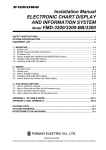
1
Back
VOYAGE DATA RECORDER
VR-5000
(Serial No. 1001 or greater)
The paper used in this manual
is elemental chlorine free.
FURUNO Authorized Distributor/Dealer
9-52 Ashihara-cho,
Nishinomiya 662-8580, JAPAN
Telephone :
0798-65-2111
Fax
0798-65-4200
:
All rights reserved.
Printed in Japan
FIRST EDITION :AUG.
: AUG. 2003
H
Pub. No. IME-44180-H
( TATA ) VR-5000
: JUL. 27, 2006
*00014865416*
*00014865416*
*00014865416*
*IME44180H00*
*IME44180H00*
*IME44180H00*
SAFETY INSTRUCTIONS
CAUTION
WARNING
ELECTRICAL SHOCK HAZARD
Observe the following compass safe
distances to prevent interference to a
magnetic compass:
Do not open the equipment
unless totally familiar with
electrical circuits and
service manual.
Only qualified personnel
should work inside the
equipment.
Turn off the power at the switchboard
before beginning the installation.
Standard
compass (m)
Steering
compass (m)
DCU
2.50
1.60
DRU
1.10
0.65
Microphone
0.55
0.35
VHF I/F unit
0.75
0.50
RAP
0.75
0.50
Fire or electrical shock can result if the
power is left on.
Do not install the equipment where it
may get wet from rain or water splash.
Water in the equipment can result in fire,
electrical shock or damage the equipment.
Attach securely grounding
to the ship's body.
Be sure that the power supply is
compatible with the voltage rating of
the equipment.
The grounding is required
to prevent electrical shock.
Connection of an incorrect power supply
can cause fire or damage the equipment.
The voltage rating of the equipment appears
on the label above the power connector.
I
CONTENTS
EQUIPMENT LIST .............................................................................................................................. III
SYSTEM CONFIGURATION ............................................................................................................... IV
Chapter 1 INSTALLATION .............................................................................................................. 1.1
1.1 INSTALLING DATA COLLECTING UNIT (DCU) .................................................................... 1.2
1.2 INSTALLING DATA RECORDING UNIT (DRU) ..................................................................... 1.6
1.3 CONNECTION OF SENSOR CABLE..................................................................................... 1.9
1.4 RADAR RGB VIDEO ............................................................................................................ 1.12
1.5 BRIDGE AUDIO .................................................................................................................... 1.15
1.6 VHF COMMUNICATION AUDIO........................................................................................... 1.17
1.7 REMOTE ALARM PANEL..................................................................................................... 1.19
1.8 POWER SUPPLY.................................................................................................................. 1.20
1.9 REMOTE JUNCTION BOX................................................................................................... 1.20
1.10 INTEGRATED ALARM SYSTEM........................................................................................ 1.20
1.11 HOW TO INCREASE CHANNEL NUMBER ....................................................................... 1.21
Chapter 2 SETUP ............................................................................................................................ 2.1
2.1 VHF INTERFACE UNIT (IF-5200) .......................................................................................... 2.1
2.2 DATA COLLECTING UNIT (VR-5010) .................................................................................... 2.2
2.3 MARKING BATTERY AND POSITION LOCATOR EXPIRY................................................... 2.3
2.4 ADJUSTMENT AFTER REPLACING THE AC/DC POWER PACK ....................................... 2.4
2.5 SYSTEM TIME ADJUSTMENT............................................................................................... 2.5
Appendix A VR-5000 INPUT SPECIFICATION ............................................................................ AP-1
PACKING LISTS ...............................................................................................................................A-1
OUTLINE DRAWINGS ......................................................................................................................D-1
INTERCONNECTION DIAGRAMS ...................................................................................................S-1
Label for expiry date .......................................................................................................................B-1
II
EQUIPMENT LIST
Standard supply
Unit
Type
Code No.
VR-5020-6G
-
VR-5020-9G
-
Data Collecting Unit (DCU)
VR-5010
-
1
Remote Alarm Panel (RAP)
VR-5016
-
1
Bridge Microphone
VR-5011
000-040-829
1
CP24-00215
004-379-590
1
For DCU
CP24-00216
004-379-960
1
For RAP
CP24-00200
000-040-833
1
IEEE1394 Cable
1394M1A1, L=30 m
CP24-00211
004-379-590
1
For DCU
SP24-00201
004-554-540
1
Two fuses for 10 A
Type
IF-8502 or
Code No.
Q’ty
-
1
1
Data Recording Unit (DRU)
Installation Materials
Spare Parts
Q’ty
1
Remarks
6 GB for connection of single radar
9 GB for connection of two radars
Including 40 GB removable hard disk
Optional supply
Unit
Remote Junction Box (RJB)
IF-8510
Remarks
Repeater
VR-5025
004-379-630
Watertight Box
VR-5012
-
VHF Interface Unit
IF-5200
-
Removable Hard Disk
VR-5014
004-379-600
Battery
VR-5015
004-381-310
1
set
Two batteries
Microphone
VR-5011
000-040-830
1
Max. 6
RS PCB
OP24-6
004-381-210
1
RS-422 board
RS PCB/Cable
OP24-7
004-381-230
1
RS-422 board w/1.5 m cable
Mic. w/watertight box
VR-5011/
5012
000-040-472
1
VR-5033-J
004-381-260
VR-5033-E
004-381-270
RS PCB
OP24-10
004-381-910
1
RS-422 board 99033-8
(For V3.00)
RS PCB & cable
OP24-11
004-381-930
1
RS-422 board 99033-8 &
cable DB37-HD78
SDRAM DIMM 256M
OP24-9
004-381-950
1
Available from Jan. 2006
Live player pro kit
For extending Firewire cable > 30 m
For microphone
1
(2)
III
To combine mic and loudspeaker
lines
40 GB
1
w/Japanese Manual
w/English Manual
SYSTEM CONFIGURATION
Data Recording Unit (DRU)
Microphone
Waterproof Box
VR-5012
VR-5020-6G or VR-5020-9G
IEEE1394 cabling
30 m
Bridge Mic
6 ch
VR-5011
VHF I/F
VHF Audio
Radar Video
IF-5200
Data Collecting
2 ch max
Unit (DCU)
1 ch (2 ch max)
GPS
Speed log
Heading
Echosounder
Autopilot
Engine telegraph
Steering gear
M/E remote system
Main air compressor
Bow thruster
Shell door system
Watertight doors
Fire doors
Anemometer
Fire detection
Main alarms
Others
RS-232C
Remote Alarm
Panel (RAP)
VR-5016
* RS-422
Remote
Junction Box
IF-85XX
VR-5010
RGB H/V
Analog
(16 ch)
IEC61162
Analog
Digital
Digital
(52 ch)
100-230 VAC
Contact
(12 ch)
IEC61162
(8 ch, 16 ch max)
*: One of IEC 61162 channels used
Fig. A System Configuration of VR-5000
Environmental category
DCU, RAP
Protected from weather
DRU
Exposed to weather
Microphone
Protected from weather
VHF I/F unit
Protected from weather
IV
Chapter 1
INSTALLATION
The basic VDR consists of Data Collecting Unit (DCU), Data Recording Unit (DRU) in
the protective capsule, six microphones and Remote Alarm Panel (RAP) which
indicates the status of the system remotely. Some optional units are available to
enhance the basic performance. For example, Remote Junction Box can minimize the
cable run and increase the number of the input port, and VHF interface IF-5200 can
combine VHF microphone and loudspeaker lines.
The VDR system continuously stores data over past 12 hours in the DRU and
removable hard disk. Oldest data is erased as a new data is entered.
The VDR operates on 115/230 VAC mains and 24 VDC power supply. In case of ship’s
mains failure, backup batteries is used for recording bridge audio for 2 hours. The
system configuration of VR-5000 is shown on the next page.
A lot of sensors are connected to the VDR in different signal types in some cases.
Determine all sensors to be connected before installation.
-1.1 -
1.1
INSTALLING DATA COLLECTING UNIT (DCU)
The Data Collecting Unit (DCU), designed for indoor installation, is mounted in a place
convenient for connection with relevant sensors and associated devices. The DCU is
mounted onto the shock absorber (the figures on next page).
General considerations
Mount the DCU where it is,
-
out of direct sunlight and away from heat sources,
-
away from places subject to water splash and rain,
-
A magnetic compass will be affected if the DCU is placed too close to the magnetic
compass. Observe the compass safe distances on page I to prevent deviation of a
magnetic compass.
-
300 mm clearance is required at least either side of the DCU.
There are two cable entries front and rear on the bottom panel. Cover the unused cable
entry to prevent a mouse from entering.
Data Processor Unit (DPU)
Removable Hard Disk
Cover
Power Distribution Unit
(PDU)
Junction box
Cable clamp
Data Collecting Unit (DCU)
-1.2 -
1.1.1 Mounting
Caution
To install the shock absorber, insert your fingers in the
holes marked by arrows and lift.
Lifting by the sides may cause the body of shock absorber
drop out of the cover because they are not attached to one
another tightly.
The DCU is fixed by using four holes in the bottom plate onto the supplied shock
absorber with four M10 bolts as follows. Fix the shock absorber onto the DCU mounting
base arranged by the shipyard with four M10 bolts, put the cover over the shock
absorber, fix the cover with supplied screws, and then fix the DCU to the shock
absorber.
Front
Front
(a) Without cover
(b) With cover
Shock absorber for DCU
1.1.2 Connection
All sensor cables except for radar video are connected to the terminals and connectors
on the junction box in the DCU. The Terminal Board is Wago spring-catch terminal
blocks for leads of up to 2.5 mm2 or AWG 14 wires.
Each terminal block has a pair of holes. Insert the lead fitting tool into a hole
corresponding to the counterpart hole where a lead is to be inserted. When the lead is
inserted in the terminal block, remove the lead tool. Make sure the lead is securely
retained in the holder.
Lead fitting tool is fixed to the right on the Terminal Board in the DCU.
Step 1. Insert the
lead fitting tool into
the right hole.
Step 2. Insert the
stripped wire into the
counterpart hole.
Lead fitting tool
Step 3. Remove the
tool. Assure the wire
is securely retained.
Location of Lead Fitting Tool (Far right of junction box)
-1.3 -
Refer to the interconnection diagram for details of right pins on the terminal boards.
Caution
Turn off the DCU before making connections.
ANALOG IN
(AN00 to AN15)
AUDIO IN
(MIC 1 to MIC 6, VHF 1 and VHF 2)
REMOTE ALARM
PANEL
SERVICE
COM
DRU
IAS
DIGITAL IN
(DC00 to DC15
and DC16 to DC31)
DIGITAL IN
RS-422 IN
(DC32 to DC47
(SI00 to SI15)
and DC48 to DC63)
24 VDC OUTPUT
24 VDC INPUT
(Not for normal use)
AC INPUT, from top
Terminals and Connectors on Junction Box in DCU
The DCU and Data Recording Unit (DRU) are connected with the supplied IEEE1394 or
FireWire* cable on which two plugs are factory-fitted at both ends. These plugs look like
the same but these are different; one has latches and the other does not. These are
labeled “DCU” and “DRU,” so run the cable accordingly.
*FireWire is the trademarked name of Apple which originally developed a very fast external bus
technology that supports data transfer rates of up to 400Mbps.
-1.4 -
Table describes the function of connectors.
Table - Terminals and connectors on TB
Connector/TB
Signal/Unit to be connected
ANALOG IN
Analog signal, 16 channels
AUDIO IN
Bridge audio, 6 channels and VHF audio, 2 channels
DIGITAL IN
Digital signal, 64 channels (52 channels for voltage signal
and 12 channels for contact-closure signal)
RS-422 IN
IEC 61162 serial data
8 channels (standard)
16 channels (max.)
REMOTE ALARM PANEL
Remote alarm panel
SERVICE COM 1
PC for servicing and setting up
DRU
Data recording unit (Turn off the unit before connection.)
IAS
Integrated Alarm System
OUTPUT 24 VDC
Optional remote junction box (max 15A)
INPUT 24 VDC
24 VDC
INPUT AC
Ship’s mains
1.1.3
Attaching card holder to door
A card holder for convenient storage of LAN cable, IEEE1394 cable, Error code table
and Data extraction procedure on the door of the DCU is available. Remove paper from
double-sided tape on the card holder and attach it to the door, aligning bottom edge of
card holder with bottom edge of door.
-1.5 -
1.2
INSTALLING DATA RECORDING UNIT (DRU)
The Data Recording Unit (DRU) includes a protective capsule and it should be installed
in the vicinity of the bridge on the open deck area of the vessel. This will maximize the
probability of its survival and facilitate recovery following an incident. The DRU should
be positioned clear of rigging and other potential obstructions and as near to the
centerline of the ship as possible. Making a guard around the DRU is recommended.
Precautions for installing the capsule
.1 Must be separated from fuel or other potential fire hazards
.2 Must be separated from probable sources of mechanical damage
.3 Avoid direct sunlight as much as possible
.4 Must be installed in a place that facilitates routing maintenance and copying of
recorded data
.5 Must be installed where a diver or remote operated vehicle could remove and retrieve
.6 There should be a clear and unobstructed area around the DRU to allow a diver or an
ROV to work
1.2.1 Mounting
The Data Recording Unit comes with the mounting bracket fitted. Request to a shipyard
to construct a mounting base of the DRU. On the mounting base, mount the bracket
with M8 bolts and nuts (double nuts). The gap between vibration absorber and bolt
should be at least 3mm.
Projection
Acoustic beacon
Band
Vibration absorber
Cradle
Gap
More than 3 mm
Projection
A: details
A
Note: If you once detach the main body from the mounting bracket, fix the main body as
shown in the figure above so that acoustic beacon should be horizontal. Then the main
body is securely fixed by the band.
How to detach the main body
1. Remove two snap pins.
2. Remove two hinge pins.
3. Lift the release levers and detach the main body.
Release lever
Hinge pin
Snap pin
-1.6 -
1.2.2 Connection
The DRU is connected to the DCU connector with a non-halogen IEEE 1394 (FireWire)
cable, 30 m with IEEE1394 connectors factory-fitted at both ends. The connector is
labeled “DCU” and “DRU” respectively.
The cable can be extended to a maximum of 70 m by using an optional repeater and
additional 40 m IEEE1394 cable.
The IEEE1394 cable from the DCU is connected to the Data Recording Unit by
following the steps below:
.1
Unscrew the cap nut.
.2
Remove and discard the dummy cable.
.3
Be sure that IEEE1394 plug is marked “DRU” and latches on the plug are cut
off. If not, the plug cannot be disconnected easily because of limited space.
.4
Remove the waterproofing cap of this cable and pass the cable through the cap nut.
.5
Put the Teflon washer and the rubber bushing as shown below.
.6
Coat the rubber bushing, screw part of the cap nut and contact part of the cable
with rubber bushing, with silicone grease.
.7
Insert the IEEE1394 plug into the receptacle.
.8
Slide the bushing down until it fits in position tightly.
.9
Hand-tighten the cap nut firmly.
IEEE1394 plug
Latch being cut off
Rubber bushing
Teflon washer Cap nut
Coat with silicone grease: •Screw part of cap nut
•Rubber bushing
•Contact part of cable with rubber bushing
Placing rubber bushing and Teflon washer
-1.7 -
Coat surface of teflon washer with
supplied silicone sealant and where
cable enters DRU.
Gap: Approx. 2.6 mm
Gap: Approx. 2.6 mm
Thread
Thread
How to tighten cap nut
Tighten DRU cap nut until one or
two threads are visible. DO NOT
tighten cap until end of thread.
Gap: Approx. 2.6 mm
Gap between cap
nut and DRU
Coat thorougly with silicone sealant
for waterproofing.
Waterproofing and cable protection
-1.8 -
1.3
CONNECTION OF SENSOR CABLE
1.3.1 IEC 61162 serial data
RS-422 IN terminal board provides eight channels to receive IEC 61162 digital data.
Receivable are all IEC 61162 sentences and binary data, but at least ZDA or GNA is
necessary for stamping date and time. The GPS receiver is connected to channel SI00
generally. Channels, SI08 to SI15 are optional. An optional remote junction box is
connected to the DCU through RS-422 interface.
TDA
TDB
RS-422 interface circuit in VR-5000
1.3.2 Non-IEC 61162 signal
.1
Analog
4 to 20 mA, 0 to 10 V and –10 to +10 V signals can be connected to ANALOG IN
terminal board of 16 channels (AN00 to AN15). Input voltage (current) range is set by
“Web-Configuration” software.
Voltage signal
The voltage between two input terminals is 24 V or less. (The A/D converter in the
Analog interface circuit has input voltage range of ±12V.)
Current signal
When 4 to 20 mA current signal is connected to ANALOG IN terminal board, a 470-ohm
resister, 1/2 W or 1 W must be connected across the input of the corresponding
ANALOG IN channel to convert the current signal to the voltage signal. See the figure
below.
4 mA to 20 mA
470 ohms,
1/2W to 1W
4 mA: 1.88 V
20 mA: 9.4 V
Connection of 4 to 20 mA current signal
-1.9 -
.2
Digital (Voltage and Contact-closure)
Two DIGITAL IN terminal boards are used to connect voltage and contact-closure
signals. Galvanic-isolated 52 channels, DC00 to DC51, are used for voltage signal and
12 channels, DC52 to DC63, for contact-closure signal. Range of input voltage is 3 to
32 V. The system sends 24 VDC to ”floating contact.”
The figures below show the digital interface circuit for voltage and contact-closure
signals respectively.
3 to 32 V
No polarity
Interfacing of “voltage” signal (DC00 to DC51)
Interfacing of “contact-closure” signal (DC52 to DC63)
Contact-closure signal can be connected to the voltage source terminal, DC00 to DC51
in the following circuit.
+
Dry contact connection to DC00 to DC51
-1.10 -
No polarity
Dry contact connection to DC00 to DC51
(Using external power supply)
24Vdc Power
supply
Dry contact connection to DC00 to DC51
(Using external power supply)
The right figure shows an example of the
terminal board (locally arranged) to
distribute 24 VDC to contact-closure
sensors.
Terminal board (locally
arranged) to distribute
24 VDC.
Example of Terminal Board for
distribution of 24 VDC
Contact-closure signal
Generally, VR-5000 is connected to a lamp in the mimic panel in parallel to obtain a
contact-closure signal. When the status indicator panel provides a dimmer control, a
diode must be used as shown in the figure below. Otherwise, active lamp leads another
lamp to be on when lamps are dimmed. Adding a resistor, instead of the diode, is
another method.
There are hundreds of fire doors in a passenger ship. These are grouped in area to
reduce the signal line to the VDR. To do so, confirm with the ship classification society.
24 V
VR-5000
or
Connection of VDR to lamps in fire door mimic panel
-1.11 -
1.4
RADAR RGB VIDEO
Interlaced or non-interlaced radar video is connected to video connector VD1 on the
PDU by 75-ohm coaxial cable. The VD1 connector includes R, G, B, Hs and Vs
connectors of BNC type. The system supports separate sync, sync-on-green (SOG),
and composite sync signals.
.1
Video signal level: 0.5 to 1 Vpp
(Minimum sync signal is 50 mV when a composite sync signal is used.)
.2
Horizontal sync signal: Max. 80 kHz, positive or negative
.3
Vertical sync signal: Max. 75 Hz
Receivable resolution is 640x480 to 1280x1024 as shown in table below.
(a)
VGA:
640 x 480
(g)
FR-15x5M3 series:
1024 x 780
(b)
Wide VGA:
852 x 480
(h)
FAR-28x5 series:
1066 x 800*
(c)
CCIR:
738 x 576
(i)
Wide XGA:
1336 x 768
(d)
SVGA:
800 x 600
(j)
SXGA:
1280 x 1024
(e)
Wide SVGA:
1067 x 600
(k)
FR-21x5:
1280 x 1024
(f)
XGA:
1024 x 768
*: Interlaced video
BNC connectors for radar, VD 1
VD2 cover plate for No. 2 radar
Front panel of Power Distribution Unit (PDU)
To add BNC connectors assy. (option);
1. Pull out the PDU and remove the VD2 cover plate on the PDU. Fix the BNC
connectors assy. on the same location and pass the cable attached to it backward.
2. Plug in the connector of the cable to Frame Grabber board in the DPU. VD2 is
connected to the second port from the bottom on Frame Grabber board. Fix the
cable with push mount cable ties (supplied as installation materials).
Frame Grabber board
Ports for VD4, VD3, VD2
and VD1 from top)
Data Processing Unit (DPU), Rear view
-1.12 -
FAR-2107 series radar
For the connection between the VR-5000 and FAR-2107 series radar, refer to the
installation manuals of FAR-2117/2127/2817/2827, FAR-2137S/2837S or
FAR-2827W/2837SW.
FR-2105 series radar
Following describes the modification on FR-2105 to connect it to the VDR.
Necessary parts
Parts Name
Type
Code Number
Q’ty
1
RGB buffer kit
RGB-BUFF board
NH-XH connector assy.
NH-XH connector assy.
OP03-162
03P9229A
NH10P-XH13P
NH4P-XH3P
008-501-130
1
2
3
BNC connector converter
2 m RGB cable
DSUB-BNC-1
KB-HD152K
000-148-528
000-152-099
1
1
The VDR I/F unit only converts D-sub connector to BNC connector.
INT board
RGB-BUFF board
XH13P
J449
RGB cable, 2m
J1
BNCx5
J2
NH10P
DB15 DB15
J449
XH3P
J463
-
J3
NH4P
BNC connector converter
FR -2105 Display Unit
Modification on FR-2105
-1.13 -
FAR-2805 series radar
Following describes the modification on FR-2805 to connect it to the VDR
Necessary Parts
1
2
3
4
Parts Name
Type
Code Number
VDR I/F kit (1)
OP03-177
008-528-270
RGB-BUFF board
03P9229A
NH-XH connector assy.
03-2057, 4-3P
NH-XH connector assy.
03-2058, 10-13P
VDA/INT chassis
03-133-1127-4
VDR I/F kit (2)
OP03-178
008-528-280
(No VDA/INT chassis)
BNC connector converter
DSUB-BNC-1
000-148-528
2 m RGB cable
KB-HD152K
000-152-099
Kit (1): For display units being produced in June 2002 and before.
Kit (2): For display units being produced in July 2002 and after.
INT board
J449
-
03-2058
XH13P
NH10P
1
1
RGB cable, 2m
J1
BNCx5
J2
XH3P
J463
-
RGB-BUFF board
Q’ty
1
DB15
DB15
J3
NH4P
03-2057
BNC connector converter
FR/FAR-2805 Display Unit
Modification on FAR-2805
The figure below illustrates how to mount CPA/TCPA board together with RGB buffer
board in FAR-2805 series radar. VDA/INT chassis should be new type, 03-133-1127-3.
CPA/TCPA board is powered from #6 (12V) and #8 (GND) of DTB-2. J463 on INT board
is used for RGB board.
Use 15 mm spacers.
CPA/TCPA board
Use 25 mm spacers.
This hole is not used.
VIDEO AMP
New VDA/INT chassis
RGB board
Mounting CPA/TCPA and RGB boards in FAR-2805
-1.14 -
1.5
BRIDGE AUDIO
The bridge microphone comes with the flush mount plate.
Fix the plate with four M4 screws. The microphone covers
an area about 10 m in diameter with the height of 2 m.
The optional watertight box VR-5012 is used when
the microphone is installed at the wing where is
subjected to a heavy water splash.
2m
About 10 m
Coverage of microphone
Example of microphone at radar station
A maximum of 6 microphones can be connected to MIC 1 to MIC 6 terminals on AUDIO
IN terminal board. A dual twisted, balanced cable carries the following signals.
P+ (Red wire): 24 VDC (+) from PDU
L (White wire): Audio signal line, balanced, 0 dBm
L (Green wire): Audio signal line, balanced, 0 dBm
P- (Black wire): 24 VDC (-) from PDU
MIC1 audio is mixed with MIC2 audio, MIC3 with MIC4, and MIC5 with MIC6
respectively.
Caution
Turn off the DCU before connecting a microphone,
otherwise the microphone will be damaged.
-1.15 -
The following consideration must be taken into account to decide the location of the
microphone.
- With clearance around it (normally overhead in the bridge)
- Away from noise sources, such as fans, motors, and loudspeakers (1 m or more
from air duct)
- Being mounted on a non-vibrating surface to keep noise to a minimum
- Fix the cable to keep noise to a minimum. If the cable runs on the ceiling without
fixing, the cable will pick up noise.
- Close to bridge workstations, helmsstand, radar display and plotting table
(Complying with IEC61996, 4.6.5)
117
120 ± 1
65 ± 0.5
150
65 ± 0.5
CUTOUT DIMENSIONS
6-φ5 (FIXING HOLES)
NAMEPLATE
60 ± 1
80 ± 0.5
100
2.5
-1.16 -
62
1.6
VHF COMMUNICATION AUDIO
A maximum of two VHF audio signals is connected to VHF 1 and VHF 2 terminals on
AUDIO IN terminal board. IMO requires one VHF audio to be recorded. A dual twisted,
balanced cable carries the following signals.
P+: 24 VDC (+) from PDU
L: Audio signal line, balanced, 0 dBm
L: Audio signal line, balanced, 0 dBm
P-: 24 VDC (-) from PDU
VHF interface unit IF-5200
The VHF interface unit, IF-5200 mixes VHF transmitting and receiving signals for the
VDR. When the VHF outputs the mixed signal, this unit is not required.
Mounting
Fix the unit using four 5 mm holes in diameter. Remove the cover to access to holes.
When non-Furuno VHF is connected to the unit, using the terminal board, remove
unused wires and connectors. Otherwise, noise problem may arise.
Audio level is adjusted by DIP switches in the interface unit after installation. See page
2-1.
116 ± 0.5
4- φ 5 (FIXING HOLES)
NAMEPLATE
148
176 ± 0.5
217
#50
94
-1.17 -
#50
Specifications
Power Supply: 24 VDC (21.6 to 31.6 VDC), 40mA
Mic input level: -16 to –56 dBm, Input impedance: >10k ohms
(Factory default: -46 dBm, 600 ohms: 10dB ATT ON)
Speaker input level: 32 to 200 ohms, 2 mW, input impedance: 10k ohms
(Factory default: 2 mW, 200 ohms: 10dB ATT OFF)
PTT Switch signal: TTL level
Output: 0 dBm±10dB, 600 ohms, balanced
When a wing handset is used, the connection is made as follows.
HANDSET
IF-5200
FM-8700
CN3 CN1 CN2
DC24V
FM10PS-6H
TTYCS-1
*
HANDSET
CC490, 1m
*
CN4
WING
HANDSET
FM14-7P
CN7 CN5 CN6
*
CC491, 1m
OUT1**
*
OUT2**
*
CN9
*
TTYCS-1
VR-5000
VHF1
VHF2
TTYCS-1
CN8
TTYC-4S
WING
HANDSET
**: OUT2 can be mixed with OUT1.
*: Fix each cable with a cable-tie at the inside of the chassis.
X2
Connection example of FM-8700, IF-5200, VR-5000
-1.18 -
1.7
REMOTE ALARM PANEL
Make sure there is a sufficient space for access to the rear cover for mounting and
cabling. The Remote Alarm Panel (RAP) is flush-mounted. See the outline drawing for
cutout size. There are two types of the RAP: D-sub and Connector types.
Turn off VR-5000, before connecting/disconnecting the RAP, otherwise PDU
board will be damaged.
Data Collecting Unit
Remote Alarm Panel
Remote
Alarm
Panel
Solder
>1>
TX > 2 >
>3>
>4>
>5>
>6>
RX > 7 >
>8>
>9>
TTYCS-4
Red1
Black1
Red2
Black2
2
1
2
3
4
5
6
7
+24 V
RX
GND
IAS OK
TX
4
1
3
5
8
7
Tighten shield of cable.
6
9
Red3
Shield
IV-1.25
Connector Housing (bottom)
90
110 ± 1
Cutout dimensions
SAVE
DIMMER
Ground Terminal
Use IV-1.25sq.
wire
144
124
ERROR
Bulkhead thickness more than 15 mm
4-φ5.5(Fixing holes)
Fasten with self-tapping screws (4X16).
124
NORMAL
21
100
110 ± 1
69
SAVE
ACK
TEST
REMOTE ALARM PANEL
Terminal Board
144
Rear View
Front View
-1.19 -
1.8
POWER SUPPLY
Connect the ship’s mains 115 or 230 VAC (max 3A) to the INPUT AC terminal board by
using 2.5 mm2 or AWG12 wire. The system can also operate from 24 VDC (max10A
battery) by using 2.5 mm2 or AWG12 wire. Observe the polarity when connecting DC
source.
Table 1.2
Power Connection
Terminal
Pin No.
Signal Type
Colors
INPUT AC
1
AC LINE
Brown wire, AC line
2
AC NEUT
Blue wire (Neutral), AC line
3
AC GND
Green/yellow wire
1
DC INPUT +
Red wire
2
DC INPU T-
Black wire
INPUT 24 VDC
1.9 REMOTE JUNCTION BOX
An optional remote junction box is connected to RS-422 IN terminal board in the DCU
by a single cable, shielded twisted pair.
1.10 INTEGRATED ALARM SYSTEM
An alarm is output from IAS terminal board to the Integrated Alarm System on board the
ship.
Pin No.
Signal Name
Description
1
IAS NC
Relay contact, normally closed
2
IAS NO
Relay contact, normally, open
3
IAS COM
Relay common
-1.20 -
1.11
HOW TO INCREASE CHANNEL NUMBER
The table below lists the maximum channel number available on VR-5000.
Data Type
Standard
Maximum
Remarks
IEC 61162
8 channels
17 channels
Install additional RS-422 I/F card in DPU for
8 channels. Use Remote Junction Box
IF-8510 for 1 channel.
Digital
64 channels
288 channels
Use Remote Junction Box.
Analog
16 channels
24 channels
Use Remote Junction Box.
Audio
8 channels
8 channels
No additional channel
Radar Video
1 channel
4 channels
Add BNC connector plate and
interconnection cable.
IEC 61162
For extra 8 channels, install optional RS-422 I/F card in the Data Processing Unit
(DPU).
This socket is not used.
RS-422 I/F card (optional)
RS-422 I/F card
Power unit
DRU I/F card
Removal hard disk
DPU with cover removed, top view
Remote Junction Box IF-8510 provides one channel for serial data interfacing.
Analog
Remote Junction Box IF-8510 provides 8 channels for analog interfacing, using two
Mitsubishi AJ65BT-64AD Analog/Digital converters. The connection is made with a
shielded twisted-pair cable.
Specification of AJ65BT-64AD
Number of input points: 4 points
Input: Voltage: 0 to ± 10 V; Current: 0 to ± 20 mA
-1.21 -
The jumper plug in the converter selects the input range. (*: Factory-default)
A*
Voltage input
Current input
B
0 to 10V
-
C
1 to 5 V
4 to 20 mA
– 10 to 10V
20 to 20 mA
D
0 to 5 V
0 to 20 mA
a) Voltage input ( 0 to ± 10V)
*1
Shield
b) Current input (0 to ± 20 mA)
*2
Shield
*3
*1: Connect a capacitor, 0.1 to 0.47 uF, 25 V to eliminate or reduce noise
and ripple if necessary.
*2: When a current signal is connected, put a jumper between V+ and I+.
*3: Ground FG1. When signal line is noisy, try to ground AG as well.
Connection on AJ65BT-64AD
Digital
Remote junction box either IF-8502 or IF-8510 is available optionally to increase the
number of digital channels. The table below shows the maximum channels on the
remote junction box. The channel number is decided when ordering: specify QX42 or
QX81 and the number of modules you need.
Modules receive voltage and contact-closure signals. Two Mitsubishi AJ65BT1-16D are
included in the module and set to either + or – common signal by changing the
connection. See the figure on next page.
RJB
Module (QX42 or QX81 selectable)
AJ65BT1-16D
(+ or - common )
QX42
(+ common, Mitsubishi)
QX81
(- common, Mitsubishi)
IF-8502
None
64 inputs x 3 pcs., max.
32 inputs x 5 pcs., max.
IF-8510
16 inputs x 2 pcs.
(standard)
64 inputs x 3 pcs., max.
32 inputs x 5 pcs., max
-1.22 -
Applicable crimp-on lug: RAV 1.25 to 3.5 or RAV 2 to 3.5 (JIS C 2805)
Connection on AJ65BT1-16D
Radar Video
BNC connector plate is fixed onto the Power Distribution Unit, and then these
connectors are wired to the Data Processing Unit (DPU).
-1.23 -
This page is intentionally left blank.
-1.24 -
Chapter 2
SETUP
This chapter describes how to setup and check the system.
2.1
VHF INTERFACE UNIT (IF-5200)
2.1.1 Audio level adjustment
DS1 and DS3 are 10 dB step attenuators for channel 1 and 2 microphone lines
respectively. Set the DIP switch so that the audio output level between #4 and #5, or #7
and #8 of CN9 is 0 dBm (2.2 Vp-p).
Factory-setting: 10 dB (ON); 20 dB (OFF); 30 dB (OFF) and 40 dB (OFF).
DS1
CN9
JP1
Channel 1 Input
DS2
#4 OUT1
#5
OUT2
#7
#8
To VDR
DS3
Channel 2 Input
DS4
Location of DIP switches and jumper wire in IF-5200
Table below lists the function of DS2 and DS4.
DIP Switch
Function
#1 (10 dB ATT)
Attenuates speaker signal by 10 dB. Factory-setting: OFF
#2 (MIX)
When set to OFF, either “mic” or “sp” signal is sent to the VDR
according to the PTT switch status. When ON, both “mic” and
“sp” signals are always sent to the VDR. Factory-setting: OFF
2.1.2 Jumper setting
Jumper wire JP1 functions as follows:
•Short circuit (Factory-setting): “input” signals from CH1 and CH2 are output from OUT 1
port and OUT 2 port respectively.
•Open circuit: “input” signals from CH1 and CH2 are output from OUT 1 port.
-2.1-
2.2
DATA COLLECTING UNIT (VR-5010)
The system configuration must be updated after installation. See VR-5000 Setup manual
for details.
The outline of the system configuration is;
Step 1. Connection of PC
Step 2. Connection of monitor
Step 3. Software configuration
Step 4. Saving configuration data
Step 5. Initialization of index file
Step 6. Restart VR-5000
Step 7. Download configuration data
Step 8. Check of recorded data
-2.2-
2.3
MARKING BATTERY AND POSITION LOCATOR EXPIRY
After installing and setting up, inscribe a expiry date of battery and acoustic beacon on
the label on the Data Collecting Unit. The battery has 4 year in-service life. The expiry
date starts at installation. The expiry date of the acoustic beacon is marked on the
acoustic beacon.
INT.BACK-UP
BATTERY-EXPIRY DATE
ACOUSTIC
LOCATOR-EXPIRY DATE
LAST ANNUAL
CHECK-DATE
Label case
Place where expiry date is written down
-2.3-
2.4
ADJUSTMENT AFTER REPLACING THE AC/DC POWER PACK
The AC/DC power pack is built in the power distribution unit in the DCU. When you
replace it with a new one, adjust the output voltage. If this adjustment is done incorrectly,
the internal batteries will not be charged and the charge indicator lamp blinks
continuously.
1. After replacing the AC/DC power pack, turn on the MAINS AC SUPPLY switch only.
2. Remove the right side cover. Connect a digital voltage meter to the power pack, and
adjust the output voltage by rotating the "+V ADJ" potentiometer at the rear panel of
the power pack so that the output voltage is 29.2±0.1 VDC.
PDU board
AC/DC power pack
View A
SP200-27
+ VADJ
+V
V
GND N
L
Digital voltage-meter
Power distribution unit (top view)
3.
View A
Confirm the output voltage from the DC/DC converter in the PDU board as follows.
a) Turn on the MAINS DC SUPPLY switch only.
b) Connect a digital voltage meter to the “OUTPUT 24 VDC” terminal in the DCU, and
confirm that the voltage is 28.0 to 28.2 VDC.
c) If it is out of that range, adjust the potentiometer on the PDU board. (If the shield
cover is attached to the PDU board, access the potentiometer from the hole in the
shield cover.)
Power distribution unit
“OUTPUT 24 VDC” terminal
DCU
-2.4-
2.5
SYSTEM TIME ADJUSTMENT
The system time, used for time-stamping VDR data, synchronizes with the UTC time if
the system time is behind the UTC time within one hour. However, the system time is set
to within two minutes (practically 10 seconds) behind the UTC time after installation to
make the synchronization faster.
Note that the system DOES NOT work if the system time is ahead of the UTC time.
To adjust the system time, a keyboard with a PS/2 connector and a SXGA monitor are
required.
To adjust system time;
1.
Connect the SXGA monitor and the keyboard to the data processing unit (DPU) in
the DCU. The VGA connector locates left of the removable hard disk.
Remove the
cap to connect
a keyboard
DPU, front view
2.
Unlock the KB/LOCK switch.
Connect SXGA
monitor.
KB/LOCK
switch
DPU front panel, cover opened
3.
4.
5.
6.
7.
8.
9.
10.
Turn on the VR-5000 while pressing and holding down the Delete key.
Wait for the BIOS screen to come up. (Keep the Delete key pressed.)
Select “Standard CMOS Feature” and press the Enter key.
Set the system time about 10 seconds behind UTC or GPS time.
Press F10, Y, and Enter keys in order to save data.
Restart VR-5000.
Lock the keyboard with the KB/LOCK switch.
Wait until system time synchronizes with the GPS time.
If it is necessary to adjust the system time frequently, the lithium battery CR-2032
on the DPU processor board in the data processing unit (DPU) may be flat.
-2.5-
This page is intentionally left blank.
-2.6-
Appendix A VR-5000 INPUT SPECIFICATION
1. Digital and Contact Inputs
Channel no.
Description
Active
Remarks
DC 00
Open
Digital input
DC 01
Open
Digital input
DC 02
Open
Digital input
DC 03
Open
Digital input
DC 04
Open
Digital input
DC 05
Open
Digital input
DC 06
Open
Digital input
DC 07
Open
Digital input
DC 08
Open
Digital input
DC 09
Open
Digital input
DC 10
Open
Digital input
DC 11
Open
Digital input
DC 12
Open
Digital input
DC 13
Open
Digital input
DC 14
Open
Digital input
DC 15
Open
Digital input
DC 16
Open
Digital input
DC 17
Open
Digital input
DC 18
Open
Digital input
DC 19
Open
Digital input
DC 20
Open
Digital input
DC 21
Open
Digital input
DC 22
Open
Digital input
DC 23
Open
Digital input
DC 24
Open
Digital input
DC 25
Open
Digital input
DC 26
Open
Digital input
DC 27
Open
Digital input
DC 28
Open
Digital input
DC 29
Open
Digital input
DC 30
Open
Digital input
DC 31
Open
Digital input
DC 32
Open
Digital input
DC 33
Open
Digital input
DC 34
Open
Digital input
DC 35
Open
Digital input
DC 36
Open
Digital input
AP.1
DC 37
Open
Digital input
DC 38
Open
Digital input
DC 39
Open
Digital input
DC 40
Open
Digital input
DC 41
Open
Digital input
DC 42
Open
Digital input
DC 43
Open
Digital input
DC 44
Open
Digital input
DC 45
Open
Digital input
DC 46
Open
Digital input
DC 47
Open
Digital input
DC 48
Open
Digital input
DC 49
Open
Digital input
DC 50
Open
Digital input
DC 51
Open
Digital input
DC 52
Open
Contact
DC 53
Open
Contact
DC 54
Open
Contact
DC 55
Open
Contact
DC 56
Open
Contact
DC 57
Open
Contact
DC 58
Open
Contact
DC 59
Open
Contact
DC 60
Open
Contact
DC 61
Open
Contact
DC 62
Open
Contact
DC 63
Open
Contact
DC 64
Open
Contact
2. Serial Inputs
Channel no.
SI 00
Description
Active
Remarks
GPS Receiver
SI 01
SI 02
SI 03
SI 04
SI 05
SI 06
SI 07
SI 08
Option
SI 09
Option
SI 10
Option
AP.2
SI 11
Option
SI 12
Option
SI 13
Option
SI 14
Option
SI 15
Option
3. Analog Inputs
Channel no.
Description
Voltage
Remarks
AN 00
AN 01
AN 02
AN 03
AN 04
AN 05
AN 06
AN 07
AN 08
AN 09
AN 10
AN 11
AN 12
AN 13
AN 14
AN 15
4. Audio Inputs
Channel no.
Description
Remarks
MIC 1
MIC 2
MIC 3
MIC 4
MIC 5
MIC 6
VHF 1
VHF 2
AP.3
This page is intentionally left blank.
AP.4
PACKING LIST
24AB-X-9852 -2
A-1
1/1
VR-5010-J/E-*-CS
N A M E
ユニット
DESCRIPTION/CODE №
O U T L I N E
Q'TY
UNIT
データ収集部
1
VR-5010-*
DATA COLLECTION UNIT
000-040-754-00
予備品
**
SPARE PARTS
予備品
1
SP24-00201
SPARE PARTS
004-555-540-00
工事材料
INSTALLATION MATERIALS
工事材料
1
CP24-00211
INSTALLATION MATERIALS
004-379-540-00
図書
DOCUMENT
エラーコードヒョウ
ERROR CODE TABLE
1
E42-00501-*
000-157-307-0*
取扱説明書
OPERATOR'S MANUAL
1
OMJ-44180-*
000-148-204-0*
**
操作要領書
OPERATOR'S GUIDE
1
OSJ-44180-*
000-148-657-0*
**
装備要領書
INSTALLATION MANUAL
1
IMJ-44180-*
000-148-655-0*
**
1.コ-ド番号末尾の[**]は、選択品の代表型式/コードを表します。
CODE NUMBER ENDED BY "**" INDICATES THE NUMBER OF TYPICAL MATERIAL.
型式/コード番号が2段の場合、下段より上段に代わる過渡期品であり、どちらかが入っています。 なお、品質は変わりません。
TWO TYPES AND CODES MAY BE LISTED FOR AN ITEM. THE LOWER PRODUCT MAY BE SHIPPED IN PLACE OF THE UPPER
PRODUCT. QUALITY IS THE SAME.
(略図の寸法は、参考値です。 DIMENSIONS IN DRAWING FOR REFERENCE ONLY.)
24AB-X-9852
A-2
CODE NO.
004-379-540
TYPE
CP24-00211
24AB-X-9401 -2
1/2
工事材料表
INSTALLATION MATERIALS
番 号
NO.
名 称
NAME
型名/規格
DESCRIPTIONS
20
PLASTIC BAND
CODE NO.
20
PLASTIC BAND
CODE NO.
10
PLASTIC BAND
CODE NO.
12
FLAT WASHER
CODE NO.
4
HEX.NUT
CODE NO.
8
SPRING WASHER
CODE NO.
六角ボルト スリ割
9
000-864-261
M10X25 SUS304
4
HEX.BOLT (SLOTTED
HEAD)
CODE NO.
六角ボルト
M10X40 SUS304
000-862-308
4
HEX.BOLT
CODE NO.
000-862-184
RT30SSF5-W
プッシュマウントタイ
10
000-863-111
M10 SUS304 バネ座金
8
000-864-131
M10 SUS304
六角ナット 1種
7
000-595-297
M10 SUS304
ミガキ平座金
6
000-570-326
CV-350N
コンベックス
5
000-809-225
CV-250N
コンベックス
4
000-808-408
CV-150HT
コンベックス
3
用途/備考
REMARKS
4
COSMETIC CAP
CODE NO.
2
数量
Q'TY
CP-30-BC-10
ボルトキャップ
1
略 図
OUTLINE
8
TIEING WIRE BAND
CODE NO.
000-153-665
24AB-X-9401
FURUNO ELECTRIC CO .,LTD.
(略図の寸法は、参考値です。 DIMENSIONS IN DRAWING FOR REFERENCE ONLY.)
A-3
CODE NO.
004-379-540
TYPE
CP24-00211
24AB-X-9401 -2
2/2
工事材料表
INSTALLATION MATERIALS
番 号
NO.
名 称
NAME
カードホルダー
11
略 図
OUTLINE
型名/規格
DESCRIPTIONS
数量
Q'TY
用途/備考
REMARKS
C-26-タテ-ニ-1
1
CARD HOLDER
CODE NO.
000-155-571
24AB-X-9401
FURUNO ELECTRIC CO .,LTD.
(略図の寸法は、参考値です。 DIMENSIONS IN DRAWING FOR REFERENCE ONLY.)
A-4
24AB-X-9854 -0
PACKING LIST
1/1
VR-5010
N A M E
ユニット
O U T L I N E
DESCRIPTION/CODE №
Q'TY
UNIT
VR-5010-VIS
DCU防振台組品
1
DCU VIBRATION ISOLATION ASSY.
004-379-550
(略図の寸法は、参考値です。
DIMENSIONS IN DRAWING FOR REFERENCE ONLY.)
24AB-X-9854
A-5
24AB-X-9403 -0
CODE NO.
1/1
TYPE
工事材料表
INSTALLATION MATERIALS
番 号
NO.
名 称
NAME
ケーブル組品
1
略 図
OUTLINE
型名/規格
DESCRIPTIONS
数量
Q'TY
用途/備考
REMARKS
1394M1A1 L=30M
1
CABLE ASSY.
CODE NO.
000-148-668
24AB-X-9403
FURUNO ELECTRIC CO .,LTD.
(略図の寸法は、参考値です。 DIMENSIONS IN DRAWING FOR REFERENCE ONLY.)
A-6
PACKING LIST
24AB-X-9853 -1
1/1
VR-5020-6G/9G
N A M E
ユニット
O U T L I N E
DESCRIPTION/CODE №
Q'TY
UNIT
VR-5020-6G
データ記録器
1
DATA RECORDER
000-040-826 **
工事材料
INSTALLATION MATERIALS
CP24-00215
工事材料
1
INSTALLATION MATERIALS
004-379-590
1.コ-ド番号末尾の[**]は、選択品の代表型式/コードを表します。
CODE NUMBER ENDED BY "**" INDICATES THE NUMBER OF TYPICAL MATERIAL.
(略図の寸法は、参考値です。
DIMENSIONS IN DRAWING FOR REFERENCE ONLY.)
24AB-X-9853
A-7
CODE NO.
004-379-590-00
TYPE
CP24-00215
24AB-X-9402 -3
1/1
工事材料表
INSTALLATION MATERIALS
番 号
NO.
名 称
NAME
略 図
OUTLINE
型名/規格
DESCRIPTIONS
数量
Q'TY
用途/備考
REMARKS
シリコンゴム
1
KE-45 100Gイリ *シロ*
SILICONE SEALANT
1
CODE NO.
000-821-026-00
シリコングリス
2
KS-650N 100G
SILICONE GREASE
1
CODE NO.
000-805-203-00
型式/コード番号が2段の場合、下段より上段に代わる過渡期品であり、どちらかが入っています。 なお、品質は変わりません。
TWO TYPES AND CODES MAY BE LISTED FOR AN ITEM.
QUALITY IS THE SAME.
THE LOWER PRODUCT MAY BE SHIPPED IN PLACE OF THE UPPER PRODUCT.
(略図の寸法は、参考値です。 DIMENSIONS IN DRAWING FOR REFERENCE ONLY.)
FURUNO ELECTRIC CO .,LTD.
24AB-X-9402
A-8
24AB-X-9856 -0
PACKING LIST
1/1
VR-5016
N A M E
ユニット
O U T L I N E
DESCRIPTION/CODE №
Q'TY
UNIT
VR-5016
リモートアラームパネル
1
RIMOTE ALARM PANEL
000-041-040
工事材料
INSTALLATION MATERIALS
CP24-00216
工事材料
1
INSTALLATION MATERIALS
004-379-960
(略図の寸法は、参考値です。
DIMENSIONS IN DRAWING FOR REFERENCE ONLY.)
24AB-X-9856
A-9
CODE NO.
004-379-960
TYPE
CP24-00216
24AB-X-9404 -3
1/1
工事材料表
INSTALLATION MATERIALS
番 号
NO.
名 称
NAME
型名/規格
DESCRIPTIONS
用途/備考
REMARKS
1
CONNECTOR
CODE NO.
000-156-337
4X16 SUS304 1シュ
+トラスタッピンネジ
2
数量
Q'TY
17JE-23090-02(D8C)
コネクタ(17JE)
1
略 図
OUTLINE
4
SELF-TAPPING SCREW
CODE NO.
000-802-080
24AB-X-9404
FURUNO ELECTRIC CO .,LTD.
(略図の寸法は、参考値です。 DIMENSIONS IN DRAWING FOR REFERENCE ONLY.)
A-10
PACKING LIST
24AB-X-9855 -2
1/1
VR-5011-CS
N A M E
ユニット
O U T L I N E
DESCRIPTION/CODE №
Q'TY
UNIT
VR-5011
マイクロフォン
1
MICROPHONE
000-040-830
工事材料
INSTALLATION MATERIALS
CP24-00217
工事材料
1
INSTALLATION MATERIALS
004-381-090
(略図の寸法は、参考値です。
DIMENSIONS IN DRAWING FOR REFERENCE ONLY.)
24AB-X-9855
A-11
CODE NO.
004-381-090
TYPE
CP24-00217
24AB-X-9405 -1
1/1
工事材料表
INSTALLATION MATERIALS
番 号
NO.
名 称
NAME
型名/規格
DESCRIPTIONS
数量
Q'TY
用途/備考
REMARKS
4X16 SUS304 1シュ
+トラスタッピンネジ
1
略 図
OUTLINE
6
SELF-TAPPING SCREW
CODE NO.
000-802-080
24AB-X-9405
FURUNO ELECTRIC CO .,LTD.
(略図の寸法は、参考値です。 DIMENSIONS IN DRAWING FOR REFERENCE ONLY.)
A-12
24AB-X-9851 -0
PACKING LIST
1/1
IF-5200
N A M E
ユニット
O U T L I N E
DESCRIPTION/CODE №
Q'TY
UNIT
IF-5200
インターフェイスユニット
1
INTERFACE UNIT
999-999-008 *
付属品
ACCESSORIES
CC490
マイク延長ケーブル1
1
MIC EXTENSION CABLE
999-999-009 *
CC491
マイク延長ケーブル2
1
MIC EXTENSION CABLE
999-999-010 *
T-18R
インシュロックタイ
6
PLASTIC BAND
999-999-011 *
1.コ-ド番号末尾の[*]は、ダミーコードに付き、注文できません。
* THIS CODE CANNOT BE ORDERED.
(略図の寸法は、参考値です。
DIMENSIONS IN DRAWING FOR REFERENCE ONLY.)
24AB-X-9851
A-13
004-555-540-00
24AE-X-9301 -0 1/1
TYPE
SP24-00201
BOX NO.
SPARE PARTS LIST FOR
SHIP NO.
ITEM
NO.
CODE NO.
NAME OF
PART
OUTLINE
U
DWG. NO.
OR
TYPE NO.
S
P
SETS PER
VESSEL
E
QUANTITY
REMARKS/CODE NO.
WORKING
PER
SET
PER
VES
SPARE
ヒューズ
1
2
FUSE
FGBO 125V 10A
PBF
MFR'S NAME
FURUNO
ELECTRIC
CO.,LTD.
000-155-826-10
DWG NO.
24AE-X-9301
1/1
(略図の寸法は、参考値です。 DIMENSIONS IN DRAWING FOR REFERENCE ONLY.)
型式/コード番号が2段の場合、下段より上段に代わる過渡期品であり、どちらかが入っています。 なお、品質は
変わりません。
TWO TYPES AND CODES MAY BE LISTED FOR AN ITEM. THE LOWER PRODUCT MAY BE SHIPPED IN PLACE OF THE
UPPER PRODUCT. QUALITY IS THE SAME.
D-1
Feb.02'05
D-2
Mar.19'04
H.Hayashi
D-3
Y. Hatai
D-4
Y. Hatai
D-5
Feb.25'05
D-6
D-7
Apr. 30
'30
インターフェイス
CN9
3 OUT-H INTERFACE
4 OUT-C
IF-5200
(No.2)
インターフェイス
CN9
3 OUT-H INTERFACE
4 OUT-C
IF-5200
(No.1)
マイクロフォン
VR-5011
(No.6)
P-
L-
L+
データ収集部
DATA COLLECTING UNIT
VR-5010
*1
TTYCS-1
*1
TTYCS-1
*1
TTYCS-1Q
1
2
3
4
5
P+
RED
GRN
WHT
BLK
マイク
MIC
マイクロフォン
VR-5011
(No.5)
LP-
L+
*1
TTYCS-1Q
1
2
3
4
5
P+
RED
GRN
WHT
BLK
マイク
MIC
マイクロフォン
VR-5011
(No.4)
LP-
L+
P+
*1
TTYCS-1Q
1
2
3
4
5
P-
RED
GRN
WHT
BLK
マイク
MIC
マイクロフォン
VR-5011
(No.3)
マイク
MIC
RED
GRN
WHT
BLK
L+
L-
P+
*1
TTYCS-1Q
*1
TTYCS-1Q
1
2
3
4
5
P-
RED
GRN
WHT
BLK
L+
L-
P+
P-
RED
GRN
WHT
BLK
L-
P+
L+
S-1
6
P+
L+
LP-
P+
L+
LP-
P+
L+
LP-
P+
L+
LP-
P+
L+
LP-
P+
L+
LP-
P+
L+
LP-
P+
L+
LP-
AUDIO IN
REMOTE2
REMOTE1
1
2
3
4
5
6
7
8
R
RG
G
GG
B
BG
H
HG
V
VG
RED
GND
GREEN
GND
BLUE
GND
HSYNC
GND
VSYNC
GND
RADAR2
5
1
2
3
4
5
6
7
8
*1
TTYCS-1Q
1
2
3
4
5
ECX-3C-2V-T
ECX-3C-2V-T
R
RG
G
GG
B
BG
H
HG
V
VG
RED
GND
GREEN
GND
BLUE
GND
HSYNC
GND
VSYNC
GND
RADAR1
1
2
3
4
5
レーダー
RADAR
(No.2)
A
マイクロフォン
VR-5011
(No.2)
4
マイク
MIC
3
マイク
MIC
マイクロフォン
VR-5011
(No.1)
2
レーダー
RADAR
(No.1)
1
MIC1
MIC2
MIC3
MIC4
MIC5
MIC6
VHF1
VHF2
SERVICE COM1
1
2
3
4
5
6
7
8
9
B
DC31
DC47
DC63
AN14
DC14
DC30
DC46
DC62
SI14
AN13
DC13
DC29
DC45
DC61
SI13
AN12
DC12
DC28
DC44
DC60
SI12
AN11
DC11
DC27
DC43
DC59
SI11
AN10
DC10
DC26
DC42
DC58
AN09
DC09
DC25
DC41
DC57
SI09
AN08
DC08
DC24
DC40
DC56
SI08
AN07
DC07
DC23
DC39
DC55
SI07
AN06
DC06
DC22
DC38
DC54
SI06
AN05
DC05
DC21
DC37
DC53
SI05
AN04
DC04
DC20
DC36
DC52
SI04
AN03
DC03
DC19
DC35
DC51
SI03
AN02
DC02
DC18
DC34
DC50
SI02
DC01
DC17
DC33
DC49
DC00
DC16
DC32
DC48
1
2
3
4
5
6
リピータ
REPEATER
CONSULT WITH SHIPOWNER AND/OR SHIPYARD ABOUT CONNECTION OF DEVICES.
注記
*1)造船所手配
*2)ドライ接点専用(COMMONは下部端子Bへ接続)
*3)ドライ接点の場合、COMMONは追加端子に接続すること
*4)Aは上部端子、Bは下部端子
*5)切断不可
NOTE
*1. SHIPYARD SUPPLY.
*2. CONTACT CLOSURE ONLY.(COMMON LINE CONNECT LOWER TERMINALS "B".)
*3. IN CASE OF CONTACT CLOSURE,
ALL COMMONS SHALL BE CONNECTED TO THE ADDITIONAL TERMINALS.
*4. A ARE UPPER TERMINAL AND B ARE LOWER TERMINAL.
*5. NEVER CUT THE CABLE.
1 LINE
2 NEUT
3 GND
REMOTE
ALARM PANEL
INPUT AC
1 24VDC(+)
2 24VDC(-)
INPUT 24VDC
24VDC(+)
24VDC(-)
1
2
3
4
5
6
MAX 0.2A
OUTPUT 24VDC
1 NC
2 NO
3 COM
APPROVED
SCALE
*1
DPYC-1.5
24VDC
DRAWN
May 31 '04
CHECKED
TITLE
K.MIYAZAWA
名称
TAKAHASHI.T
Y. Hatai
C4418-C01- B
CONNECTOR WITH NO LATCH
RED1
BLK1
*1
TTYCS-4
RED2
RED1
BLK1
RED2
RED3
BLK2
BLK2
RED3
1
2
3
4
5
6
7
TB
+12V
RX
GND
IAS OK
TX
リモート
アラーム
パネル
REMOTE
ALARM
PANEL
VR-5016
VR-5000
航海情報記録装置
相互結線図
MASS
kg
DWG No.
1
2
3
4
5
6
7
8
9
1
2
3
4
5
6
データ記録器
DATA RECORDING
UNIT
VR-5020-6/9
100-230VAC
1φ,50/60Hz
*1
DPYC-2.5
警報システム
ALARM SYSTEM
SI00
各信号の接続に関しては造船所/船主との事前打合せが必要です。
1
2
3
4
5
6
DCU
*5
1394M1A1,30m
DC IN
IAS
*1
TTYCS-1, etc
1
2
3
4
5
6
SI01
IEC61162データ
出力機器
IEC6116 DATA
OUTPUT DEVICE
*1
TTYCS-1, etc
DRU
SI10
*2 *3
デジタル信号出力機器
(接点信号12チャンネル)
DIGITAL SIG. OUTPUT DEVICE
(CONTACT CLOSURE 12ch)
AN00
*1
TTYCS-1, etc
AN01
*4
A B
1
2
DC15
RS-422 IN
*4
B A
SI15
*4
B A
IEEE1394
(FIRE WIRE)
DIGITAL IN
*4
A B
デジタル信号出力機器
(電圧信号52チャンネル)
DIGITAL SIG. OUTPUT DEVICE
(VOLTAGE SIG.52ch)
D
アナログ信号出力機器
(最大16チャンネル)
ANALOG SIG. OUTPUT DEVICE
(MAX.16ch)
*1
TTYCS-1
C
DIGITAL IN
*4
B A
(OPTION)
ANALOG IN
*4
B A
AN15
NAME
VOYAGE DATA RECORDER
INTERCONNECTION DIAGRAM
FURUNO ELECTRIC CO., LTD.
S-2
1
2
3
A
VHFインターフェイス
VHF INTERFACE
IF-5200
*2
FM10PS-6H
ハンドセットハンガー
HANDSET HANGER
HSC701K-B20
マイクレセプタクル
ボックス
MIC RECEPTACLE BOX
RBD-VHF/VHF-B
No.1
B
1
2
3
4
5
6
1
2
3
*1
TTYCY-4S
P
P
4
CN3
0V
PTT SW
MIC-H
MIC-C
SP(H)
THRU1
CN4
0V
PTT SW
MIC-H
MIC-C
SP(H)
THRU1
THRU2
0V
1
2
3
4
5
6
7
8
1
2
3
4
5
6
7
8
CN7/8
CN5
0V
0V
PTT SW PTT SW
MIC-H
MIC-H
MIC-C
MIC-C
SP(H)
SP(H)
THRU1
THRU1
THRU2
THRU2
0V
0V
1
2
3
4
5
6
7
8
CN6
CN9
0V
24VDC(+) 1
PTT SW 24VDC(-) 2
MIC-H
3
MIC-C
OUT1(H) 4
OUT1(L) 5
SP(H)
6
THRU1
OUT2(H) 7
THRU2
OUT2(L) 8
0V
1
2
3
4
5
6
7
8
*2
NH8P
付属ケーブル
ATTACHED CABLE
CC490,1m
*2
NH8P
付属ケーブル
ATTACHED CABLE
CC491,1m
VHF送受信機
VHF TRANSCEIVER UNIT
FM-8500
HANDSET
*2
FM10PS-6H J1105
1 0V
2 PTT SW
3 MIC-H
4 MIC-C
5 HS SP
6 HOOK SW
*2
FM14-7P
1
2
3
4
5
6
7
WING HANDSET
J602
0V
W_PTT SW
W_MIC
W_SP
TX/RX
+15V
0V
ウイングハンドセット
WING HANDSET
*3
HS6000FZ-6/5
マイクレセプタクル
ボックス
MIC RECEPTACLE BOX
RBD-VHF/VHF-B
No.2
1
2
3
*1
TTYCY-4S
P
P
4
C
ウイングハンドセット
WING HANDSET
*3
HS6000FZ-6/5
*1
TTYCS-1
*1
TTYCS-1
*1
TTYCS-1
24VDC
VHF-1
L+
LVHF-2
L+
L-
VR-5000
データ収録ユニット
DATA COLLECTING UNIT
VR-5010
TB-12
2 A
3 B
TB-13
2 A
3 B
VR-3000/3000S
データ収録ユニット
DATA COLLECTING UNIT
VR-3010
注記
*1)造船所手配。
*2)工場にて取付済み。
*3)1台のウイングハンドセットを共用する。
D
NOTE
*1. SHIPYARD SUPPLY.
*2. FITTED AT FACTORY.
*3. ONE WING HANDSET IS USED IN COMMON.
DRAWN
MAY 23, '06
CHECKED
APPROVED
SCALE
DWG.No.
TITLE
E.MIYOSHI
TAKAHASHI.T
名称
Y. Hatai
MASS
C4418-C02- J
kg
NAME
IF-5200 (W/FM-8500)
VHFインターフェイス
相互結線図
VHF INTERFACE
INTERCONNECTION DIAGRAM
S-3
2
1
3
VHF送受信機
VHF RADIO
FM-8700
A
VHFインターフェイス
VHF INTERFACE
IF-5200
*2
FM10PS-6H
ハンドセットハンガー
HANDSET HANGER
HSC701K-B20
マイクレセプタクル
ボックス
MIC RECEPTACLE BOX
RBD-VHF/VHF-B
No.1
B
1
2
3
4
5
6
1
2
3
*1
TTYCY-4S
P
P
4
CN3
0V
PTT SW
MIC-H
MIC-C
SP(H)
THRU1
1
2
3
4
5
6
7
8
ウイングハンドセット
WING HANDSET
*3
HS6000FZ-6/5
マイクレセプタクル
ボックス
MIC RECEPTACLE BOX
RBD-VHF/VHF-B
No.2
1
2
3
4
C
*1
TTYCY-4S
P
P
1
2
3
4
5
6
7
8
CN4
0V
PTT SW
MIC-H
MIC-C
SP(H)
THRU1
THRU2
0V
CN5
0V
PTT SW
CN7/8
MIC-H
MIC-C
0V
SP(H) PTT SW
THRU1
MIC-H
THRU2
MIC-C
SP(H)
0V
THRU1
THRU2
0V
1
2
3
4
5
6
7
8
1
2
3
4
5
6
7
8
CN6
CN9
0V
24VDC(+) 1
PTT SW 24VDC(-) 2
MIC-H
3
MIC-C
OUT1(H) 4
SP(H)
OUT1(L) 5
THRU1
6
THRU2
OUT2(H) 7
0V
OUT2(L) 8
ウイングハンドセット
WING HANDSET
*3
HS6000FZ-6/5
*2
NH8P
*2
NH8P
送受信部
TRANSCEIVER UNIT
FM-8700
付属ケーブル
HANDSET
*2
ATTACHED CABLE FM10PS-6H J1105
CC490,1m
1 0V
2 PTT SW
3 MIC-H
4 MIC-C
5 HS SP
6 HOOK SW
付属ケーブル
ATTACHED CABLE
CC491,1m
クロ BLK
ミドリ GRN
アカ RED
アオ BLU
シロ WHT
*1
TTYCS-1
*1
TTYCS-1
*1
TTYCS-1
デュプレクサユニット
DUPLEXER UNIT
DX-8700
WING HANDSET
TB201
0V
W_PTT SW
W_MIC
W_SP
F_GND
*4
1
2
3
4
5
24VDC
VHF-1
L+
LVHF-2
L+
L-
VR-5000
データ収録ユニット
DATA COLLECTING UNIT
VR-5010
TB-12
2 A
3 B
TB-13
2 A
3 B
VR-3000/3000S
データ収録ユニット
DATA COLLECTING UNIT
VR-3010
注記
*1)造船所手配。
*2)工場にて取付済み。
*3)1台のウイングハンドセットを共用する。
*4)コネクタプラグを取り外して結線する。
D
NOTE
*1. SHIPYARD SUPPLY.
*2. FITTED AT FACTORY.
*3. ONE WING HANDSET IS USED IN COMMON.
*4. CONNECT CORES AFTER REMOVE CONNECTOR PLUG.
DRAWN
Jun. 26,'06
CHECKED
APPROVED
SCALE
DWG.No.
TITLE
E.MIYOSHI
TAKAHASHI.T
名称
Y.Hatai
MASS
C4418-C03- K
kg
NAME
IF-5200 (W/FM-8700)
VHFインターフェイス
相互結線図
VHF INTERFACE
INTERCONNECTION DIAGRAM
Label for expiry date
If necessary, cut each label and use for inscribing the expiry date.
INT.BACK-UP
BATTERY-EXPIRY DATE
INT.BACK-UP
BATTERY-EXPIRY DATE
ACOUSTIC
LOCATOR-EXPIRY DATE
ACOUSTIC
LOCATOR-EXPIRY DATE
LAST ANNUAL
CHECK-DATE
LAST ANNUAL
CHECK-DATE
INT.BACK-UP
BATTERY-EXPIRY DATE
INT.BACK-UP
BATTERY-EXPIRY DATE
ACOUSTIC
LOCATOR-EXPIRY DATE
ACOUSTIC
LOCATOR-EXPIRY DATE
LAST ANNUAL
CHECK-DATE
LAST ANNUAL
CHECK-DATE
INT.BACK-UP
BATTERY-EXPIRY DATE
INT.BACK-UP
BATTERY-EXPIRY DATE
ACOUSTIC
LOCATOR-EXPIRY DATE
ACOUSTIC
LOCATOR-EXPIRY DATE
LAST ANNUAL
CHECK-DATE
LAST ANNUAL
CHECK-DATE
Save the label inserting the label case on the Data collecting unit.
B.1