1
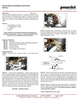
Form No. 0453-433 Arctic Cat® ATV Installation Instructions - Accessory Kit Recoil Starter Kits (p/n 1436-002 & 1436-007) NOTE: Read these installation instructions thoroughly and carefully before beginning the installation process. It is recommended that this kit be installed by an authorized Arctic Cat dealer. Application: 2007 650 H1 FIS and 650 H1 TBX 2007 650 H1 TRV 4. Using a vise grip or a channel lock pliers, remove the hardened spacer located behind the nut. Discard the spacer. See Fig. 2. Fig. 2 Kit includes: p/n QTY DESCRIPTION 0820-036 1 Starter Cup 0820-001 1 Recoil Starter Assembly 0826-038 4 Machine Screw (6 mm) 0830-108 1 O-Ring (Starter Cup) 2406-301 1 Side Panel (Left Side) * 2406-325 1 Side Panel (Left Side) ** 0453-433 1 Instructions * Included in Kit (p/n 1436-002) ** Included in Kit (p/ 1436-007 1. Remove the seat and left-side panel. 2. Remove the ten torx-head screws, lock nuts, and plastic rivet securing the foot peg and footrest. Remove the two self-tapping torx-head screws securing the inner splash panel to the footrest; then remove the footrest and set aside. Retain all hardware. See Fig. 1. 3. Remove the four torx-head screws securing the outer magneto cover; then remove the 14 mm nut. See Fig .1 Fig. 1 ATV-135 NOTE: If the spacer does not come off easily, lightly tap on the spacer to help loosen the spacer for easier removal taking care not to damage the seal. If the spacer still can’t be removed, it may be necessary to remove the outer engine cover. See an appropriate Arctic Cat ATV Service Manual for instructions. 5. Install O-Ring (p/n 0830-108) into the starter cup Oring groove which is located near the inside edge of the starter cup. 6. Apply a liberal amount of ATV High Performance Grease (p/n 0436-501) to the O-ring and the seal area on the starter cup. Carefully install the starter cup onto the end of the shaft taking care that the splines on the starter cup and the splines on the shaft are aligned. See Fig. 3. CAUTION: It is very important that the splines on the starter cup and on the shaft are aligned before tightening the nut securing the starter cup. Improper alignment will cause damage to the splines. ATV-134 Fig. 3 Fig.4 ATV-136 ATV-137 7. Reinstall the 14 mm nut and tighten to 3.9 kg-m (28 ft-lb). Install Recoil Cover Assembly (p/n 0826-038) and secure with four Machine Screws (p/n 0826038). Tighten to 1.1 kg-m (8 ft-lb). See Fig. 4. 8. Reinstall the footrest and footpeg using existing hardware. Install new left-side Side Panel (p/n 2406301) or (p/n 2406-325) and the seat. Printed in the U.S.A. ®™Trademarks of Arctic Cat Inc., Thief River Falls, MN 56701 (2) 0107