1
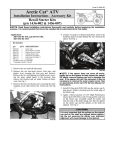
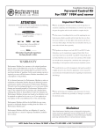
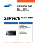
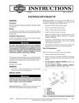
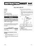
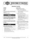
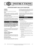
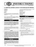
-J03792
REV. 2005-05-18
PASSENGER FOOTPEG MOUNTING KIT
GENERAL
is00521
Kit Number
50210-06
Models
This kit fits all 2006 and later Dyna model motorcycles with
original equipment solo seat and no footpegs. It is required
when installing a 2-up seat on these models.
1
This kit is also a direct replacement for the standard equipment
passenger footpeg (footrest) mounting brackets on 2006 and
later Dyna models with original equipment 2-up seats.
Additional Parts Required
Proper installation of this kit requires the installation of a passenger footpeg on each mounting bracket. See a Harley-Davidson dealer. Refer to the appropriate Parts Catalog for original
equipment footrests, or see the current Harley-Davidson
Genuine Motor Accessories and Parts catalog for a selection
of operator and passenger footpegs.
2
1. Debris deflector
2. Self-tapping screws (3)
Figure 1. Debris Deflector Removal
The rider's safety depends upon the correct installation
of this kit. Use the appropriate service manual procedures.
If the procedure is not within your capabilities or you do
not have the correct tools, have a Harley-Davidson dealer
perform the installation. Improper installation of this kit
could result in death or serious injury. (00333a)
3.
See Figure 2. Remove the spring clip (1) from the left side
of the rear axle. Loosen, but do not remove, the rear axle
nut (2).
4.
Turn the axle adjusters (3) on each side of the rear wheel
counterclockwise about the same amount to move the
rear wheel forward and allow slack in the drive belt.
NOTE
This instruction sheet references Service Manual information.
A Service Manual for your model motorcycle is required for
this installation and is available from a Harley-Davidson Dealer.
Special tools are required for the installation of this kit. We
recommend that this kit be installed by a factory-trained technician at a Harley-Davidson dealer.
is00522
2
Kit Contents
See Figure 5 and Table 1.
INSTALLATION
Left Side
1.
Block the motorcycle under the frame so the rear wheel
is off the ground.
2.
See Figure 1. Remove the three self-tapping screws (2),
and remove the debris deflector (1) from the vehicle.
1
3
1. Spring clip
2. Rear axle nut
3. Rear axle adjuster (2)
Figure 2. Rear Axle Nut and Adjusters
-J03792
Many Harley-Davidson® Parts & Accessories are made of plastics and metals which can be recycled.
Please dispose of materials responsibly.
1 of 3
NOTE
When removing the belt guard, make sure the belt guard does
not contact the fender or the fender paint will be scratched.
5.
See Figure 3. Remove and retain the front (1) and rear
(2, 3) upper belt guard fasteners, and carefully remove
the upper belt guard from the vehicle.
11. Obtain the right-side footpeg support (1) and two selftapping screws (3) from the kit. Install the support to the
mounting location as shown, and torque the screws to 2535 ft-lbs (34-47 Nm).
Footpegs
is00514
is00515
3
2
2
3
1
1
4
1. Spring washer
2. Rounded side of mounting end
3. Footpeg MUST fold upward and to the rear
5
Figure 4. Proper Footpeg Installation
NOTES
See Figure 4. The spring washer (1) goes between the jaws
of the footpeg support bracket along with the mounting end of
the footpeg.
1.
2.
3.
4.
5.
Front button-head screw and washer
Rear button-head screw and washer
Hex flanged lock nut
Hex head cap screw (2)
Belt guard mounting bracket
Footpegs must be installed in the bracket with the rounded
side (2) of the mounting end inboard. When footpegs are
properly installed, footpegs will fold upward (3) at a 45° angle
toward the rear of the motorcycle.
Figure 3. Upper Belt Guard Removal
6.
Remove the two hex head cap screws (4) that attach the
belt guard mounting bracket (5) to the rear fork. The
bracket and screws can be discarded.
Footrests must fold up and toward rear of motorcycle if
struck. Failure to set footrests to fold up and back could
result in death or serious injury. (00366a)
7.
See Figure 5. Obtain the left-side footpeg support (2) and
two self-tapping screws (3) from the kit. Install the support
to the mounting location as shown, and torque the screws
to 25-35 ft-lbs (34-47 Nm).
12. See Figure 5. Install a passenger footpeg (purchased
separately) on each footpeg support as shown, using a
hex head cap screw (4), spring washer (5) and lock nut
(6) from the kit.
8.
Install the upper belt guard with the fasteners removed
earlier. Tighten the screws to 10-15 ft-lbs (13.5-20.3 Nm).
BELT ADJUSTMENT AND VEHICLE
ALIGNMENT
9.
Install the debris deflector with the three screws removed
earlier. Tighten the screws to 40-60 in-lbs (4.5-6.8 Nm).
Refer to REAR BELT DEFLECTION in the Service Manual,
and follow the procedures given to inspect and adjust rear belt
deflection.
Right Side
10. Remove and discard the two plastic hole plugs (B) from
the rear fork (A).
-J03792
See the VEHICLE ALIGNMENT section in the Service Manual
to properly align the vehicle.
2 of 3
SERVICE PARTS
is00513
4
2
3
3
D
1
5
6
5
6
4
C
D
B
A
Figure 5. Service Parts, Passenger Footpeg Mounting Kit
Table 1. Service Parts Table
Item
Description (Quantity)
Part Number
1
Support, passenger footpeg (right side)
49224-06
2
Support, passenger footpeg (left side)
49230-06
3
Screw, button head, self-tapping, 3/8-16 x 1 in. (4)
4059
4
Cap screw, hex head, 3/8-16 x 1-1/2 in. (2)
4721
5
Spring washer (2)
50912-72
6
Hex lock nut, 3/8-16 (2)
7778
Items mentioned in text, but not included in kit:
A
Rear fork
B
Hole plug (2)
C
Belt guard mounting bracket
D
Passenger footpeg (2)
-J03792
3 of 3