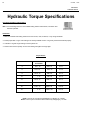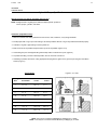
1
51-3880, 11/08 QC Series 210 Series Hydraulic Windrow Sweepers for Skid Loaders Sweepster Serial Number____________________ Manual Number: 51-3880 Release Date: November 3, 2008 Serial Number 0733001 and Up 800-456-7100 www.paladinbrands.com Sweepster 2800 N. Zeeb Rd., Dexter, MI 48130 United States of America 51-3880, 11/08 51-3880, 11/08 Table of Contents Section 1 ... Installation.................................................... 5-13 Section 2 ... Operation and Maintenance...................... 15-23 Section 3 ... Service......................................................... 25-30 Section 4 ... Parts............................................................ 31-43 Section 5 ... Options........................................................ 45-54 Section 6 ... Appendix..................................................... 54-61 51-3880, 11/08 51-3880, 11/08 Installation Manual QC Series Angle Brooms Table of Contents Introduction................................................................ 6 Safety Information.................................................7-13 General Safety Information.....................................7-8 Safety Signs & Labels......................................... 10-11 Product Information Section..................................... 12 Installation/Storage.................................................. 13 51-3880, 11/08 SAFETY SECTION INTRODUCTION Introduction Contacting SWEEPSTER Importance of this Manual If you have any questions about information in this manual or need to order parts, please call, write, fax or e-mail SWEEPSTER. Read this manual before attempting to operate the equipment. This operator’s manual should be regarded as part of the sweeper. Suppliers of both new and secondhand sweepers are advised to keep documentation indicating that this manual was provided with the sweeper. The manual contains information regarding installation, operation and maintenance required for this sweeper and optional equipment. It also includes detailed parts lists. Purpose of Sweeper This sweeper is designed solely for use in construction cleanup, road maintenance, grounds maintenance and similar operations. Use in any other way is considered contrary to the intended use. Compliance with and strict adherence to operation, service and repair conditions, as specified by the manufacturer, are also essential elements of the intended use. SWEEPSTER 2800 North Zeeb Road Dexter, Michigan 48130 Phone: (734) 996-9116 - (800) 456-7100 FAX: (734) 996-9014 e-mail: [email protected] For help with installation, operation or maintenance procedures, contact our Technical Service Department. Direct product questions and parts orders to our Sales Department. When ordering parts or accessories, be prepared to give the following information: •Sweeper model, serial number and date of purchase •Prime mover, make and model •Part number, description and quantity This sweeper should be operated, serviced and repaired only by persons who are familiar with its characteristics and acquainted with relevant safety procedures. Terms Used in Manual Accident prevention regulations, all other generally recognized safety regulations and all road traffic regulations must be observed at all times. Right-hand, left-hand, front and rear are determined from the operator’s perspective (either the operator’s seat or standing behind a walk-behind unit), facing forward in the normal operating position. Any modifications made to this sweeper may relieve the manufacturer of liability for any resulting damage or injury. Prime mover refers to the tractor, truck, loader or tow vehicle that the sweeper is mounted on or towed by. Safety Alert Symbol Optional Equipment This safety alert symbol indicates important safety messages in this manual. When you see this symbol, be alert to the possibility of injury. Carefully read the message that follows and inform other operators. Installation instructions for optional equipment, if applicable, appear in the Service Manual Section. Specifications & Features Due to continuous product improvement, specifications and features may change without notice. Warranty To validate the warranty for this unit, fill out the warranty card or warranty pages located at the back of this manual. Then, send this information to SWEEPSTER. 51-3880, 11/08 Safety Information Read this manual Read all safety information in this manual. All operators must read and understand the entire contents of this manual before sweeping. General safety practices are listed on Safety Information pages and specific safety information is located throughout this manual. Hazard Definitions Four hazard classifications are used in this manual. They are DANGER - Indicates an imminently hazardous situation which, if not avoided, will result in death or serious injury. WARNING - Indicates a potentially hazardous situation which, if not avoided, could result in death or serious injury. CAUTION - Indicates a potentially hazardous situation which, if not avoided, may result in minor or moderate injury. NOTICE - Used for instructions when machine damage may be involved. Operation CAUTION - A sweeper is a demanding machine. Only fully trained operators or trainee operators under the close supervision of a fully trained person should use this machine. Before operating sweeper: •Learn sweeper and prime mover controls in an off-road location. •Be sure that you are in a safe area, away from traffic or other hazards. •Check all hardware holding the sweeper to the prime mover, making sure it is tight. •Replace any damaged or fatigued hardware with properly rated fasteners. See Maintenance Section •Make sure all hydraulic hardware and hydraulic fittings are tight. •Replace any damaged or fatigued fittings or hoses. SAFETY SECTION GENERAL SAFETY INFORMATION •Check prime mover tire pressure before sweeping. •Check tire ratings to be sure they match the prime mover load. Weigh the sweeper end of the prime mover, if necessary, to insure proper tire rating. •Remove from the sweeping area all property that could be damaged by flying debris. •Be sure all persons not operating the sweeper are clear of the sweeper discharge area. • Always wear proper apparel such as a long-sleeved shirt buttoned at the cuffs; safety glasses, goggles or a face shield; ear protection; and a dust mask. While operating sweeper: •When operating sweeper, adhere to all government rules, local laws and other professional guidelines for your sweeping application. WARNING - Never raise the sweeper more than a few feet off the ground. The sweeper can tip back or the prime mover can tip over causing death or serious injury, • Before leaving the operator’s area for any reason, lower the sweeper to the ground. Stop the prime mover engine, set the parking brake and remove the key from the ignition. • Minimize flying debris - use the slowest rotating speed that will do the job. See Operation Section: Operating Tips • Keep hands, feet, hair and loose clothing away from all moving parts. • Leave the brush hood (shield) and all other shields and safety equipment in place when operating the sweeper and prime mover. • Be aware of the extra weight and width a sweeper adds. Reduce travel speed accordingly. See Product Information Section: Operating the Sweeper. • When sweeping on rough terrain, reduce speed to avoid “bouncing” the sweeper. Loss of steering can result. • Never sweep toward people, buildings, vehicles or other objects that can be damaged by flying debris. • Only operate the sweeper while you are in the operating position. The safety restraint must be fastened while you operate the prime mover. Only operate the controls while the engine is running. Protective glasses must be worn while you operate the prime mover and while you operate the sweeper. • While you operate the sweeper slowly in an open area, check for proper operation of all controls and all protective devices. Note any needed repairs during operation of the sweeper. Report any needed repairs. 51-3880, 11/08 SAFETY SECTION GENERAL SAFETY INFORMATION Service & Repair - General CAUTION - Do not modify the sweeper in any way. Personal injury could result. If you have questions, contact your dealer or SWEEPSTER. Repair or adjust the sweeper in a safe area, away from traffic and other hazards. Before adjusting or servicing - lower the sweeper to the ground, set parking brake, shut down the prime mover and remove the key from the ignition. When working on or around the sweeper, safely secure it from falling or shifting. Service & Repair - Hydraulic Safety Stop the prime mover engine and release hydraulic pressure before servicing or adjusting sweeper hydraulic systems. WARNING - Escaping hydraulic fluid can have enough pressure to penetrate the skin, causing serious personal injury. Check lines, tubes and hoses carefully. Do not use your hand to check for leaks. Use a board or cardboard to check for leaks. Tighten all connections to the recommended torque. See Appendix. Do not bend high pressure lines. Do not strike high pressure lines, Do not install bent lines, bent tubes, or kinked hoses. Do not install damaged lines, damaged tubes, or damaged hoses. Repair loose lines, loose tubes, and loose hoses. Repair damaged lines, damaged tubes, and damaged hoses. Leaks can cause fires. See your SWEEPSTER dealer for repair or replacement parts. Replace the parts if any of the following conditions are present: •The end fittings are damaged or leaking. •The outer covering is chafed or cut. •The reinforcing wire layer is exposed. •The outer covering is ballooning locally. •The hose is kinked or crushed. •The hoses have been pulled or stretched. Make sure that all clamps, guards, and shields are installed correctly. 51-3880, 11/08 Notes 10 51-3880, 11/08 SAFETY SECTION SAFETY SIGNS & LABELS Safety Signs and Labels There are several specific safety signs on this sweeper. The exact location of the hazards and the description of the hazards are reviewed in this section. Placement or Replacement of Safety Signs Instructions 1. Clean the area of application with nonflammable solvent, and then wash the same area with soap and water. 2. Allow the surface to fully dry. 3. Remove the backing from the safety sign, exposing the adhesive surface. 4. Apply the safety sign to the position shown in the diagram above and smooth out any bubbles. • Keep all safety signs clean and legible. • Replace all missing, illegible, or damaged safety signs. • Replacement parts, for parts with safety signs attached, must also have safety signs attached. • Safety signs are available, free of charge, from your dealer or from SWEEPSTER. 7 6 5 4 7 2 3 4 Item 2. 3. 4. 5. 6. 7. 50-0634 50-0643 50-0721 50-0722 50-0724 50-0726 Part Qty 1 2 2 1 1 2 Description Label, Serial Number Label, Tie Down Point Label, Warning, Crush Hazard Label, Warning, Misuse Hazard Label, Warning, High Pressure Fluid Hazard Label, Warning, Flying Objects & Entanglement 51-3880, 11/08 11 SAFETY SECTION SAFETY SIGNS AND LABELS Safety Signs and Labels 2. 50-0634 3. 50-0643 4. 6. 50-0721 5. 50-0722 7. 50-0726 50-0724 12 51-3880, 11/08 OPERATION SECTION PRODUCT SPECIFICATIONS Product Information Section QC Brush Head Approximate Weight with SAE J2513 Mounting Specifications and Model Views Maximum Width at 0° Articulation Maximum Length at 0° Articulation Maximum Width at 0° Articulation Maximum Length at 0° Articulation Maximum Length at Full Articulation Maximum Width at Full Articulation Sweeping Width at 0º Articulation Sweeping Width at Full Articulation Maximum Width at Full Articulation Single Motor Dual Motor 793 lbs 829 lbs 5 Ft 852 lbs 890 lbs 6 Ft 915 lbs 953 lbs 7 Ft 982 lbs 1022 lbs 8 Ft 71 inches with SAE J2513 Mounting 70.5 inches 5 Ft 82.5 inches 6 Ft 94.5 inches 7 Ft 106.5 inches 8 Ft 79.5 inches 5 Ft 82.5 inches 6 Ft 85.5 inches 7 Ft 88.5 inches 8 Ft 72 inches 5 Ft 82 inches 6 Ft 93 inches 7 Ft 103 inches 8 Ft 60 inches 5 Ft 72 inches 6 Ft 84 inches 7 Ft 96 inches 8 Ft 54 inches 5 Ft 64 inches 6 Ft 75 inches 7 Ft 85 inches 8 Ft Maximum Length at Full Articulation 51-3880, 11/08 13 INSTALLATION SECTION INSTALLING/REMOVING SWEEPER & STORAGE Sweeper Installation (Broom to Prime Mover) WARNING - Improper attachment of sweeper could result in injury or death. Do not operate this machine until you have positive indication that the attachment is securely mounted. 1. Position the broom on a level surface. Removing the Sweeper WARNING - Serious injury or death may result from disengaging the sweeper when the sweeper is in an unstable position or carrying a load. Place the sweeper in a stable position before disengaging. NOTICE - Hoses for the sweepers must be removed before the quick attach is disengaged. Pulling the sweeper with the hoses could result in damage to the prime mover or the sweeper. 2. Enter the prime mover. 3. Fasten the safety restraints. 1. Lower the broom to the ground. 4. Start the engine. 5. Disengage the parking brake. 2. Engage the parking brake and shut down the prime mover. Be sure to relieve pressure to the auxiliary hydraulic lines. 6. Align the attachment mechanism with the mounting on the broom, attach to the prime mover. Follow the attaching procedure in the prime mover owners manual. 3. Unfasten safety restraints and exit prime mover. 7. Engage the parking brake and shut down the prime mover. Be sure to relieve pressure to the auxiliary hydraulic lines. 5. Disconnect the broom hydraulic lines from the prime mover. Connect quick couplers together to keep clean. 8. Unfasten safety restraints and exit the prime mover. 9. Lock jack stands in stowed position. (if available) 10. Ensure that the hydraulic quick couplers are clean. Connect hydraulic lines for the broom to the prime mover. Twist the collar of the quick couplers one quarter of a turn in order to secure the hydraulic connections. 11. While the loader arms are lowered, visually inspect the attachment mechanism to ensure that it is securely mounted. 12. Enter prime mover, fasten safety restraints and start the prime mover. 13. Carefully raise the loader and cycle the rollback/dump cylinders to check clearances, that limiting stops make proper contact and verify that all mounting procedures have been successfully completed. Contact SWEEPSTER for instructions if the limiting stops do not contact properly. 4. Lock jack stands in lowered position. (if available) 6. Disengage attachment locking mechanism. (mechanical type) 7. Enter prime mover, fasten safety restraints and start the prime mover. 8. Disengage attachment mechanism. (hydraulic type) 9. Disengage the parking brake, and back away from the broom. Storage NOTICE - Do not store the sweeper with weight on the brush. Weight will deform the bristles, destroying the sweeping effectiveness. To avoid this problem, place the sweeper on blocks or use storage stands. Do not store polypropylene brushes in direct sunlight. The material can deteriorate and crumble before the bristles are worn out. Keep polypropylene brush material away from intense heat or flame. 14 51-3880, 11/08 Notes 51-3880, 11/08 Operation and Maintenance Manual QC Series Angle Brooms Table of Contents Operation..............................................................16-18 Operation .........................................................................16 Leveling Sweeper.........................................................17-18 Maintenance.........................................................19-23 Brush Pattern Adjustment..................................................19 Maintenance Schedule......................................................20 Maintenance Record..........................................................21 Replacing Brush Sections..................................................22 Lubrication Points............................................................. 23 15 16 51-3880, 11/08 OPERATION SECTION SWEEPING/OPERATING TIPS Before Each Use 4. Engage the brush and then lower it to the ground. Perform daily maintenance as indicated in Maintenance Schedule. 5. Increase prime mover engine rpm to sweeping speed. Run the prime mover and sweeper at a slow idle. Check for hydraulic leaks or other problems and make corrections, if necessary, before using the sweeper. See “Hydraulic inspection guideline” . WARNING - Avoid serious injury. Check for large objects that could harm the operator or others if thrown by the sweeper. Remove these items before operating. During Use Directing Debris Carry the sweeper low to the ground so that the operator has good visibility and stability. Avoid any sudden movements. Avoid excessive downward pressure on the brush sections to prevent excessive wear. A two to four inch wide pattern is sufficient for most applications. Ensure that the adjustment bolts are equally adjusted in order to prevent an uneven wear pattern. To adjust brush pattern see “Adjusting Brush Pattern”. Direct debris by angling the brush head in that direction. Observe wind direction. Sweeping with the wind makes sweeping more effective and helps keep debris off the operator. The terms swing and angle are used interchangeably. Manual Angle 1. Remove the quick release pin from the swing plate. 2. Position the brush head at the desired angle, aligning holes in the swing plate and mounting frame. 3. Re-insert the quick release pin. Hydraulic Angle 1. Start the prime mover. 2. Position the brush head at the desired angle by using 6. Travel forward at 5 mph (8 kph) or less. NOTICE - Avoid sweeper damage. Reduce travel speed to avoid hitting immovable objects. Operating Tips NOTICE- Avoid sweeper damage. Do not ram into piles. Use an appropriate attachment for this type of job. Brush, Engine & Travel Speeds Vary brush, engine and travel speeds to match sweeping conditions. Large Areas When sweeping a large area, such as a parking lot, make a path down the middle and sweep to both sides. This reduces the amount of debris that the sweeper must sweep to one side. Snow Fast brush speeds and slow travel speeds are needed to sweep snow effectively. Start at 3/4 throttle and the lowest gear of the prime mover. For wet and/or deep snow, increase to almost full throttle. This helps keep snow from packing up inside the brush hood. In deep snow you may need to make multiple passes to get down to a clean surface. To keep snow from blowing back onto a swept area, always sweep so the wind is at your back. Dirt & Gravel To keep dust at a minimum, use the optional dust suppression kit or plan sweeping for days when it is overcast and humid or after it has rained. Also, sweep so the wind blows at your back. Low brush speeds and moderate travel speeds work best for cleaning debris from hard surfaces. Brush speeds that are too fast tend to raise dust because of the aggressive sweeper action. Sweeping To sweep gravel, use just enough brush speed to “roll” the gravel, not throw it. To sweep: Heavy Debris 1. Manual angle only - Swing the brush head assembly the direction that you want to direct debris. Travel slowly - 2-3 mph. (3-5 kph) 2. Start the prime mover at idle and raise the brush. 3. Hydraulic angle only - Swing the brush head assembly the direction that you want to direct debris. Sweep a path less than the full width of the sweeper. Increase engine speed if debris becomes very heavy. 51-3880, 11/08 17 MAINTENANCE SECTION LEVELING THE SWEEPER Leveling Level the sweeper for even brush wear and effective use. CAUTION - Avoid injury. Before adjusting the sweeper, always turn off the sweeper and the prime mover engine and remove the key. 1. Move the sweeper to a flat, paved surface. 2. Lower the brush head assembly so the brush is 2 inches (51 mm) above the ground. 3. Engage the parking brake and shut down the prime mover. Be sure to relieve pressure to the auxiliary hydraulic lines. 4. Unfasten safety restraints and exit prime mover. figure 1 5. Check if the swing assembly is level by using a bubble level. To make corrections: Adjust tilt cylinders. If the front of the swing assembly is high, extend tilt cylinders. If low, retract cylinders. 6. Position the brush head assembly straight ahead. On each side, measure from the brush frame to the ground (figure 1). If measurements are not equal: Loosen hardware that attaches the swing assembly to the brush head assembly; lower the high side of the brush head until both sides are an equal distance above the ground. Tighten the hardware. (figure 2) figure 2 18 51-3880, 11/08 MAINTENANCE SECTION LEVELING THE SWEEPER High High Low Low Low figure 3 High Low figure 5 Low High High Low High High figure 4 7. Measure to see if the brush head assembly is level when angled. First, angle the brush head to the right. Measure as in step 4. Then, angle the brush head to the left. Measure again. If measurements are equal, the sweeper is level. If not, proceed with this step. Low Low High figure 6 To correct leveling problems shown in: • figure 3, extend tilt cylinders. • figure 4, retract tilt cylinders. • figure 5, loosen hardware that attaches the swing assembly to the brush head assembly; lower the left-hand side of the brush head until both sides are an equal distance above the ground. Tighten the hardware. • figure 6, loosen hardware that attaches the swing assembly to the brush head assembly; lower the righthand side of the brush head until both sides are an equal distance above the ground. Tighten the hardware. 51-3880, 11/08 19 MAINTENANCE SECTION BRUSH PATTERN/SPRING CHAIN/TRANSPORT CHAIN Setting Brush Pattern A properly adjusted brush offers the best sweeper performance. To check the brush pattern: 1. Move the sweeper to a dusty, flat surface. 2. Set the prime mover’s parking brake and leave the engine running. 3. Start the sweeper at a slow speed: lower it so the bristle tips touch the ground. Run the sweeper in a stationary position for 10 seconds. 4. Swept Area Raise the sweeper and back away; switch off the engine and remove the key. The brush pattern left in the dust should be 2-4 inches (51-102 mm) wide, running the length of the brush. (Compare the swept area with figure 7.) 2-4 in. (51-102 mm) 5. Adjust the brush pattern as necessary according to instructions found in adjusting the Spring-Chain Assembly. Figure 7 Adjusting Spring-Chain Assembly The transport chain supports the weight of the brush head assembly during transport between work sites and during adjustment of the spring-chain assemblies. The spring-chain assembly allows the brush head to pivot up and down. To adjust the brush pattern: 1. Lower the sweeper. 2. Tighten the transport chain and lower the sweeper so the transport chain supports weight. 3. Move the spring chain forward in the swing assembly chain holder to lower the brush head or backward in the holder to raise it. Tightening Transport Chain To adjust the transport chain: 1. Extend tilt cylinders. 2. Tighten the transport chain. 3. Retract tilt cylinders. 20 51-3880, 11/08 MAINTENANCE SECTION MAINTENANCE SCHEDULE Maintenance Schedule Procedure Brush head assembly - Level Brush pattern - Check (See Pattern Adj. Section) Cylinders - Retract rods - Grease threaded and ball ends to prevent rust Filter, air, prime mover - Clean Fittings/hoses, hydraulic - Check for leaks/tighten Check for damage Fittings, zerk - Grease. (See lubrication points) Oil, hydraulic - Check Level Hardware - Check for tightness Before Each Use After Each Use 100 Hours 500 Hours See Prime Mover Manual 51-3880, 11/08 21 MAINTENANCE SECTION MAINTENANCE RECORDS Maintenance Record Use this log to record maintenance performed on the sweeper. Date Maintenance Procedure Performed Performed By Comments 22 51-3880, 11/08 MAINTENANCE SECTION REPLACING BRUSH SECTIONS Replacing Brush Sections 1. Remove motor mount screws. Retain hardware for reinstallation. Remove motor mount. 2. Remove bearing mounting plate screws from side. Retain hardware for reinstallation. 3. Remove core from brush head assembly. 4. Remove one half of bearing mount plate from bearing. 5. Remove retaining plate from core assembly. 6. Remove old sections. 7. Install new sections by doing the following: a. Slide the first section onto the core with the drive pins on each side of a tube. Make sure that the drive pins angle up. (figure 1) figure 1 b. Install a second section with drive pins rotated 180° from those on the first section. ( figure 2) c. Continue installing sections, rotating each section 180° until the core is full. 8. Reattach the section retainer and bearing mounting plate with previously removed hardware. 9. Lay core on ground. Lower frame over core. 10. Reattach bearing mounting plate with previously removed hardware. 11. Reattach motor mount with hardware removed in first step. figure 2 51-3880, 11/08 23 MAINTENANCE SECTION LUBRICATION POINTS Lubrication Points The following grease fittings should be greased before each use. See figure for locations. 1. Core bearing (1 fitting - single motor only) 2. Brush Head Pivot (2 fitting) Not Shown: Hydraulic Angle Cylinder (1 fitting) 1 2 24 51-3880, 11/08 Notes 51-3880, 11/08 25 Service Manual QC Series Angle Brooms Table of Contents Troubleshooting .................................................26-30 Brush Head........................................................................26 Spring-Chain......................................................................27 Lift & Swing........................................................................27 Hydraulic System...............................................................28 Hydraulic Hose Routing.....................................................29 Wiring Harness..................................................................30 26 51-3880, 11/08 SERVICE SECTION TROUBLESHOOTING Brush Head Problem Possible Cause Possible Solution Brush rotates in wrong direction Hoses installed incorrectly Switch hoses at brush head tubes Brush slows or stops when sweeping Brush pattern too wide Adjust brush pattern to 2-4 inches (51-101mm) wide: see Maintenance: Adjusting Brush Pattern Travel speed too fast Travel no more than 5 mph (8 kph) while sweeping (2-3 mph recommended) Trying to sweep too much material at once Make several passes with sweeper Relief pressure set too low Set relief pressure to 2000 psi (138.0 bars) Filter plugging Change or clean hydraulic oil filter Brush head assembly “bounces” during sweeping Travel speed too fast and/or brush speed too slow Find correct combination of ground and brush speeds: do not travel at more than 5 mph (8 kph) Brush wears into cone shape Sweeper is not level Level sweeper before each use: see Maintenance: Leveling Tires on prime mover at different Check tire sizes and rating: make pressures or are different sizes corrections as necessary Brush wears very quickly Brush pattern too wide Adjust brush pattern to 2-4 inches (51-101mm) wide: see Maintenance: Setting Brush Pattern 51-3880, 11/08 27 SERVICE SECTION TROUBLESHOOTING Spring-Chain Assemblies Problem Springs on spring-chain assemblies stretching Possible Cause Possible Solution Transport chain too loose when traveling between job sites Adjust according to Adjustment: Transport Chain Travel speeds too fast when sweeping Do not travel at speeds over 5 mph (8 kph). Hydraulic Cylinders - Lift & Swing Problem Hydraulic cylinder neither extends nor retracts Hydraulic cylinder only extends or only retracts Hydraulic cylinder extends or retracts too quickly Possible Cause Possible Solution Manual valve - Control rods not connected or are binding Check control rod linkage; make sure all parts are connected and are not binding; fix if necessary Electric valve - No power from controls because wires are broken or disconnected Reconnect wires if disconnected; replace wires if broken Electric valve - No power from controls because switch is broken Replace switch Both types of valves - Hydraulic oil level too low Fill tank to 2-3 inches (51-76mm) from top of tank with ISO VG-46 oil Both types of valves - Hoses or fittings loose or disconnected Tighten hoses and fittings Both types of valves - Restriction in hoses Remove bends in hoses, remove obstructions inside hoses Electric valve - Set screw in flow divider on manifold out of adjustment Loosen jam nut and then turn set screw in until it stops; turn set screw out 1 1/2 turns; tighten jam nut Electric valve - Dirt or debris in spools Contact Sweepster Technical Service Manual valve - Flow too high because restrictor fitting missing from cylinder Reinstall restrictor fitting on barrel end of cylinder Manual valve - Flow too high even though restrictor fitting is installed Contact Sweepster for smaller orifice fitting 28 51-3880, 11/08 SERVICE SECTION TROUBLESHOOTING Hydraulic System Problem Possible Cause Hydraulic system overheats Hydraulic motor seals leak Possible Solution Hydraulic oil level too low Add hydraulic oil to tank until it comes to 2 inches (51mm) from top Restriction in hoses Remove bends in hoses; remove obstructions inside hoses / Replace Hose Host pump flow rate exceeds maximum rate of broom Contact host manufacturer for proper flow control method Back pressure exceeds 1000 psi Contact Sweepster Motor is failing High number of hours on motor; Contact dealer to rebuild or replace Hydraulic Schematic A B P T P Pressure T Tank 51-3880, 11/08 29 SERVICE SECTION MOTOR PORTS Hydraulic Hose Routings TANK PRESSURE TANK PRESSURE PRESSURE TANK TANK PRESSURE TANK PRESSURE Manual Angle: Connect pressure line to female quick disconnect. Connect return line to male quick disconnect. Hydraulic Angle: Connect pressure line to female quick disconnect . Connect return line from brush motor(s) to “P” port on manifold. Connect “T” port on manifold to male quick disconnect. Note: Quick Disconnect Set-Up Your broom comes equipped with standard ISO 16028 hydraulic quick disconnects (QD’s). They are factory installed using the broom female QD as the detended pressure line. If your skid steer loader male QD is not the detended pressure line you will need to swap the positions of the broom QD’s. APPLICATION TO TO APPLICATION FROM ARNESS TO PPLICATION APPLICATION TO IDENTIFICATION FROM F E B C D A G H F E C D A PLUG - A, D, E, GG & BH H VIEW "A-A" IDENTIFICATION A A + A A 1.0 D C B 1.0 A TO APPLICATION F G H D C B A H G F E A B C D C B Qty Description TO APPLICATION Item Part E B C D A F H G 1. 07-3152 1 Circuit Breaker 2. 07-0868 1 Switch 3. 07-1824 1 Rubber Boot CONTROL OUT A A 1.0 BATTERY NEGATIVE- BATTERY + POSITIVE VIEW "A-A" PLUG - A, D, E, G & H FROM LAF444 WIRE HARNESS D IDENTIFICATION E B C A F H G D FROM TO APPLICATION LAF441 WIRE HARNESS A A 1.0 BATTERY NEGATIVE- BATTERY + POSITIVE VIEW "A-A" PLUG - A, D, E, G & H BATTERY + POSITIVE A F A E E B C D A F H G PLUG - A, D, E, G & H C B A A 1.0 BATTERY NEGATIVE- BATTERY + POSITIVE VIEW "A-A" CONTROL OUT A,D,E,G,H PLUG D A F H E G B A A A A,D,E,G,H PLUG B G H A,D,E,G,H PLUG IDENTIFICATION CONTROL OUT A 1.0 BATTERY NEGATIVE- APPLICATION C A,D,E,G,H PLUG H D A A F 2 A F E A E G TO B B E G CONTROL OUT IDENTIFICATION FROM C B A A,D,E,G,H PLUG A,D,E,G,H PLUG H TO APPLICATION BATTERY NEGATIVE 1.0 BATTERY + BATTERY POSITIVE NEGATIVE- TO POSITIVE APPLICATION FROM B D A CONTROL FOUT C H G CONTROL OUT PLUG - A, D, E, G & H CONTROL OUT BATTERY NEGATIVE- BATTERY + POSITIVE VIEW "A-A" FROM LAF441 WIRE HARNESS IDENTIFICATION APPLICATION TO D A CATION FROM F H E G A TO APPLICATION TO Wiring Harness LAF441 WIRE HARNESS LAF441 WIRE HARNESS OM IRE HARNESS 1 WIRE HARNESS APPLICATION SERVICE SECTION TROUBLESHOOTING E PLUG - A, D, E, G & H WIRE HARNESS PLUG - A, D, E, G & H F444 WIRE HARNESS VIEW "A-A" LAF444 WIRE HARNESS VIEW "A-A" LAF444 WIRE HARNESS BATTERY TION E HARNESS 51-3880, 11/08 30 1 3 B B B A B A B 51-3880, 11/08 31 Parts Manual QC Series Angle Brooms Table of Contents Parts Lists......................................................................32-43 Brush Head Frames...........................................................32 Core Assemblies................................................................33 Shaft Assembly..................................................................34 Motor Bucket Assembly.....................................................35 Hydraulics-Dual Motor..................................................36-38 Hydraulics-Single Motor................................................39-40 Brush Head Stand.............................................................41 Brush Frame Labels..........................................................42 Quick Attach.......................................................................43 21059MH-XXXX 5 FT 21059MM-XXXX 5 FT 21060MH-XXXX 5 FT 21060MM-XXXX 5 FT 21061MH-XXXX 5 FT 21061MM-XXXX 5 FT QC, 32”, Single 18 ci, Hydraulic Angle Broom QC, 32”, Single 18 ci, Manual Angle Broom QC, 32”, Single 24 ci, Hydraulic Angle Broom QC, 32”, Single 24 ci, Manual Angle Broom QC, 32”, Dual, 18 ci, Hydraulic Angle Broom QC, 32”, Dual, 18 ci, Manual Angle Broom 21071MH-XXXX 6 FT 21071MM-XXXX 6 FT 21072MH-XXXX 6 FT 21072MM-XXXX 6 FT 21073MH-XXXX 6 FT 21073MM-XXXX 6 FT QC, 32”, Single 18 ci, Hydraulic Angle Broom QC, 32”, Single 18 ci, Manual Angle Broom QC, 32”, Single 24 ci, Hydraulic Angle Broom QC, 32”, Single 24 ci, Manual Angle Broom QC, 32”, Dual 18 ci, Hydraulic Angle Broom QC, 32”, Dual 18 ci, Manual Angle Broom 21083MH-XXXX 7 FT 21083MM-XXXX 7 FT 21084MH-XXXX 7 FT 21084MM-XXXX 7 FT 21085MH-XXXX 7 FT 21085MM-XXXX 7 FT QC, 32”, Single 18 ci, Hydraulic Angle Broom QC, 32”, Single 18 ci, Manual Angle Broom QC, 32”, Single 24 ci, Hydraulic Angle Broom QC, 32”, Single 24 ci, Manual Angle Broom QC, 32”, Dual 18 ci, Hydraulic Angle Broom QC, 32”, Dual 18 ci, Manual Angle Broom 21096MH-XXXX 8 FT 21096MM-XXXX 8 FT 21097MH-XXXX 8 FT 21097MM-XXXX 8 FT QC, 32”, Single QC, 32”, Single QC, 32”, Dual QC, 32”, Dual 24 ci, Hydraulic Angle Broom 24 ci, Manual Angle Broom 18 ci, Hydraulic Angle Broom 18 ci, Manual Angle Broom 32 51-3880, 11/08 PARTS SECTION BRUSH HEAD FRAME Brush Head Frames Item Part 1. 2. 3. 4. 5. 6. 7. 8. 9. 10. 11. 12. 13. Qty Description 07-0249 1 07-2952 18 07-3311 1 07-3617 27 07-3842 4 07-4927 6 07-6056 8 13-10004 2 13-12617 1 13-16417 1 13-13278 1 13-13279 1 13-12857 1 13-13280 1 13-13594 1 13-13047 1 13-13048 1 13-16416 1 13-13281 1 13-13282 1 13-13049 1 13-13283 1 13-13595 1 Chain, 1/4 x 22 Screw, HFH, CL10.9, M6-1 x 20 Link, Quick, 5/16 Nut, Insert, M6 x 1 Ring, Snap Washer, Fender, CL8.8, M6 Nut, Flange, M10-1.5 Pin, Pivot, Left Arm, QA Plate, Mounting, Brush Head, Pivot Weld, Brush Frame, 4 Ft Weld, Brush Frame, 5 Ft Weld, Brush Frame, 6 Ft Weld, Brush Frame, 7 Ft Weld, Brush Frame, 8 Ft Weld, Brush Frame, 9 Ft Sheet, Hood, Side, Left Sheet, Hood, Side, Right Sheet, Hood, 4 Ft Sheet, Hood, 5 Ft Sheet, Hood, 6 Ft Sheet, Hood, 7 Ft Sheet, Hood, 8 Ft Sheet, Hood, 9 Ft 51-3880, 11/08 33 PARTS SECTION CORE ASSEMBLIES Core Assemblies 5 1 3 2 4 Item Part 1. 2. 3. 4. 5. Qty Description 01-1201 1 01-1085 1 01-0930 1 01-0931 1 01-0933 1 01-1148 1 01-1200 1 01-0272C1 01-0020C1 01-0079C1 01-0080C1 01-0530C 1 07-2952 4 07-3617 4 13-13166 1 13-16418 1 13-13284 1 13-13285 1 13-12899 1 13-13286 1 13-13596 1 Section, Set, 32, 10, Mixed, Convoluted ( 4 Ft ) Section, Set, 32, 10, Mixed, Convoluted ( 5 Ft ) Section, Set, 32, 10, Mixed, Convoluted ( 6 Ft ) Section, Set, 32, 10, Mixed, Convoluted ( 7 Ft ) Section, Set, 32, 10, Mixed, Convoluted ( 8 Ft ) Section, Set, 32, 10, Mixed, Convoluted ( 9 Ft ) Section, Set, 32, Poly, Convoluted ( 4 Ft ) Section, Set, 32, Poly, Convoluted ( 5 Ft ) Section, Set, 32, Poly, Convoluted ( 6 Ft ) Section, Set, 32, Poly, Convoluted ( 7 Ft ) Section, Set, 32, Poly, Convoluted ( 8 Ft ) Section, Set, 32, Poly, Convoluted ( 9 Ft ) Screw, HFH, CL10.9, M6-11 x 20 Nut, Insert, M6 x 1 Plate, Ring, Core, End, QC Weld, Core, 4 Ft, Hex Drive Weld, Core, 5 Ft, Hex Drive Weld, Core, 6 Ft, Hex Drive Weld, Core, 7 Ft, Hex Drive Weld, Core, 8 Ft, Hex Drive Weld, Core, 9 Ft, Hex Drive 34 51-3880, 11/08 PARTS SECTION SHAFT ASSEMBLY Shaft Assembly 3 10 4 5 11 4 2 5 1 8 3 Item Part 1. 2. 3. 4. 5. 6. 7. 8. 9. 10. 11. Qty Description 07-2495 4 07-3738 1 07-3745 8 07-3747 14 07-3748 10 07-3777 1 07-4514 4 08-0067 1 13-11903 1 13-12941 2 13-12974 1 Screw, HHC, CL8.8, M10-1.5 x 35mm Washer, Lock, Split, Medium, M8 Washer, Flat, CL8.8, M10 Washer, Lock, Split, Medium, M10 Screw, HHC, CL10.9, M10-1.5 x 25mm Screw, HHC, CL10.9, M8-1.25 x 20mm Nut, Hex, CL10, M10-1.5 Bearing, 1 1/4, 4 Bolt Washer, .34 x 1.8 x 10Ga Plate, Shaft, Brush Frame, Mounting Weld, Shaft, Hex Drive 4 7 9 6 51-3880, 11/08 35 PARTS SECTION MOTOR BUCKET ASSEMBLIES Motor Bucket Assemblies Item Part Qty Description 1. 03-4682 1 Motor, Hydraulic, White, 17.9 Cu In, with Check Valve, Right (Dual Motor) 03-4634 1 Motor, Hydraulic, White, 17.9 Cu In, with Check Valve, Left (Single or Dual Motor) 03-4425 1 Motor, Hydraulic, White, 24.9 Cu In, with Check Valve, Left (Single Motor) 2. 07-3745 4 Washer, Flat, CL8.8, M10 3. 07-3747 10 Washer, Lock, Split, Medium, M10 4. 07-3748 4 Screw, HHC, CL10.9, M10-1.5 x 25mm 5. 07-3749 6 Screw, HHC, CL10.9, M10-1.5 x 30mm 6. 07-4610 2 Nut, Hex, Lock, CL10.9, M12-1.75 7. 07-6178 2 Screw, Socket Head, M12-1.75 x 35mm 8. 13-12946 1 Weld, Motor Bucket 9. 13-15206 1 Hub, Hex, 2 1/2 x 1 1/4, Tapered Bore x 3.75 10. 13-16225 1 Plate, Receiver, Hex, 2.50 Replacement Parts for 03-4682, 03-4634, and 03-4425 Motors : 03-3081 Seal Kit 07-4657 Key 07-4568 Shaft Nut 03-5543 Shaft Motor 36 51-3880, 11/08 PARTS SECTION HYDRAULIC ASSEMBLIES Hydraulic Assemblies - Dual Motor 7 6 3 2 9 5 8 Item Part Qty 1. 03-1939 2. 03-5160 3. 03-5161 03-5162 03-5163 03-5164 4. 03-5165 03-5166 03-5167 03-5168 5. 07-3740 6. 07-4604 7. 07-4942 8. 07-5287 9. 13-15094 10. RHW8614 11. RHW8616 4 2 2 2 2 2 2 2 2 2 1 4 4 3 1 3 3 Description Fitting, 10MB-10MF Tee, 12MF-12MF-12MF, Bulkhead Hose, .50 x 68, 10FF-12FF45, 3.5K (5 ft) Hose, .50 x 75, 10FF-12FF45, 3.5K (6 ft) Hose, .50 x 80, 10FF-12FF45, 3.5K (7 ft) Hose, .50 x 86, 10FF-12FF45, 3.5K (8 ft) Hose, .50 x 32, 10FF-12FF, 3.5K (5 ft) Hose, .50 x 38, 10FF-12FF, 3.5K (6 ft) Hose, .50 x 44, 10FF-12FF, 3.5K (7 ft) Hose, .50 x 50, 10FF-12FF, 3.5K (8 ft) Screw, HHC, CL10.9, M8-1.25 x 30mm Nut, Hex, Lock, CL10.9, M8-1.25 Washer, Fender, 1 1/2 x 5/16 Screw, HHC, CL10.9, M8-1.25 x 65mm Bracket, Mounting, Bulkhead Tees Cover Plate Hose Cradle 10 11 1 4 51-3880, 11/08 37 PARTS SECTION HYDRAULIC ASSEMBLIES Hydraulic Assemblies - Dual Motor Manual Angle 2 1 7 3 8 5 6 9 4 Item Part Qty Description 1. 2. 3. 4. 5. 6. 7. 8. 9. Hose, .63 x 140, 12FF-12MB, 2.75K, HS Screw, HHC, Gr8, 5/16-18 x 2 1/2 Screw, HHC, CL10.9, M8-1.25 x 30mm Nut, Hex, Lock, CL10.9, M8-1.25 Washer, Fender, 1 1/2 x 5/16 Weld, Plate Cover, Plate Hose, Cradle Hose, Spring 03-5169 07-1784 07-3740 07-4604 07-4942 RHW8613 RHW8614 RHW8616 RHW8618 2 1 1 1 2 1 1 1 1 5 38 51-3880, 11/08 PARTS SECTION HYDRAULIC ASSEMBLIES Hydraulic Assemblies - Dual Motor Hydraulic Angle 11 20 rn tu Re 9 21 12 6 re su s re 7 P 16 19 14 22 4 8d 8c 8 18 13 10 8a 5 2 Item Part 1. 2. 3. 4. 5. 6. 7. 8. 8a 8b 8c 8d 03-2291 03-2352 03-2396 03-4700 03-4887 03-5169 03-5173 03-5215 03-5280 07-7150 07-7151 07-7152 07-7153 07-7134 Qty Description 4 2 1 1 1 1 1 1 1 1 1 1 2 2 Fitting, 6MF-6MB, 6F5OLO-S Hose, .38 x 32, 6FF-6FF90, 4.75K Elbow, 90, 10MF-12MB Elbow, 45, 10MF-12MB Cylinder, 2.50 x 1.38 x 7.50, 3.5K Hose, .63 x 140, 12FF-12MB, 2.75K, HS Hose, .63 x 60, 10FF-12FF, 3.625K Manifold, Swing, 12 Volt Manifold, Swing, 24 Volt Valve, Cartridge, Pressure Comp Valve, Cartridge, Relief Valve, Cartridge, Directional Coil, 12 Volt Coil, 24 Volt Replacement Part for 03-4887 Cylinder : 03-4888 Seal Kit 03-5035 Cylinder Rod 3 1 Item Part 9. 10. 11. 12. 13. 14. 15. 16. 17. 18. 19. 20. 21. 22. 17 8b 8 16 Qty Description 03-5385 07-0206 07-1784 07-3740 07-4604 07-4622 07-4942 07-7131 13-11248 LAF9441 RHW8613 RHW8614 RHW8616 RHW8618 1 2 1 1 1 2 2 2 2 1 1 1 1 1 Hose, .63 x 80, 10FF-10MB, 3K, HS Pin, Cotter, Gr2, 3/16 x 2 Screw, HHC, Gr8, 5/16-18 x 2 1/2 Screw, HHC, CL10.9, M8-1.25 x 30mm Nut, Hex, Lock, CL10.9, M8-1.25 Nut, Hex, Lock, CL10.9, M10-1.5 Washer, Fender, 1 1/2 x 5/16 Screw, HHC, CL10.9, M10-1.5 x 160mm Bushing, 1 x .406 x 1 Wire, Assembly, 9 ft Weld, Plate Cover, Plate Hose, Cradle Hose, Spring 51-3880, 11/08 39 PARTS SECTION HYDRAULIC ASSEMBLIES Hydraulic Assembly - Single Motor Manual Angle 5 11 2 1 13 4 6 6 10 8 3 7 12 Item Part 8 7 11 9 Qty Description 1. 03-1939 2. 03-4804 3. 03-5153 4. 03-5154 5. 07-1784 6. 07-3740 7. 07-4604 8. 07-4942 9. 07-5287 10. RHW8613 11. RHW8614 12. RHW8616 13. RHW8618 2 2 2 2 1 3 5 8 2 1 3 3 1 Fitting, 10MB-10MF Fitting, 10MF-10MF, UN Hose, .50 x 80, 10FF-12MB, 3.5K, HS Hose, .50 x 112, 10FF- 10FF, 3.5K Screw, HHC, 5/16-18 x 2 1/2 Screw, HHC, CL10.9, M8-1.25 x 30mm Nut, Hex, Lock, CL10.9, M8-1.25 Washer, Fender, 1 1/2 x 5/16 Screw, HHC, CL10.9, M8-1.25 x 65mm Weld, Plate Cover, Plate Hose, Cradle Hose, Spring 40 51-3880, 11/08 PARTS SECTION HYDRAULIC ASSEMBLIES Hydraulic Assembly - Single Motor Hydraulic Angle n tur Re Pr e ur s es 9c 9d 9a Item 1. 2. 3. 4. 5. 6. 7. 8. 9. 9a 9b 9c 9d 10. 11. 12. Part 03-1939 03-2291 03-2352 03-2396 03-4700 03-4887 03-5153 03-5154 03-5215 03-5280 07-7150 07-7151 07-7152 07-7153 07-7134 03-5383 07-0206 07-1784 Qty Description Item 2 4 2 1 1 1 1 1 1 1 1 1 1 2 2 1 2 1 13. 07-3740 3 Screw, HHC, CL10.9, M8-1.25 x 30mm 14. 07-4604 5 Nut, Hex, Lock, CL10.9, M8-1.25 15. 07-4622 2 Nut, Hex, Lock, CL10.9, M10-1.5 16. 07-4942 8 Washer, Fender, 1 1/2 x 5/16 17. 07-5287 2 Screw, HHC, CL10.9, M8-1.25 x 65mm 18. 07-7131 2 Screw, HHC, CL10.9, M10-1.5 x 160mm 19. 13-11248 2 Bushing, 1 x .406 x 1 20. LAF9441 1 Wire, Assembly, 9ft 21. RHW8613 1 Weld, Plate 22. RHW8614 3 Cover, Plate 23. RHW9616 3 Hose, Cradle 24. RHW9618 1 Hose, Spring Replacement Part for 03-4887 Cylinder : 03-4888 Seal Kit 03-5035 Cylinder Rod Fitting, 10MB-10MF Fitting, 6MF-6MB, 6F5OLO-S Hose, .38 x 32, 6FF-6FF90, 4.75K Elbow, 90, 10MF-12MB Elbow, 45, 10MF-12MB Cylinder, 2.50 x 1.38 x 7.50, 3.5K Ball Hose, .50 x 80, 10FF-12MB, 3.5K, HS Hose, .50 x 112, 10FF-10FF, 3.5K Manifold, Swing, 12 Volt Manifold, Swing, 24 Volt Valve, Cartridge, Pressure, Comp Valve, Cartridge, Relief Valve, Cartridge, Directional Coil, 12 Volt Coil, 24 Volt Hose, .50 x 195, 10FF-12MB, 3K, HS Pin, Cotter, Gr2, 3/16 x 2 Screw, HHC, Gr8, 5/16-18 x 2 1/2 Part 9b Qty Description 51-3880, 11/08 41 PARTS SECTION BRUSH HEAD STANDS Brush Head Stands Item Part 1. 2. 3. 4. Qty Description 07-0260 07-0699 07-4748 13-13226 2 2 2 2 Pin, Clevis, Gr2, 3/8 x 2 3/4 Pin, Cotter, Gr2, 1/8 x 1 1/4 Pin, Lock, 3/8 x 2, Grip, Square, 2.50AL Weld, Stand, Brush Head 42 51-3880, 11/08 PARTS SECTION BRUSH HEAD LABELS Brush Head Labels 7 6 5 1 7 4 2 3 4 Item Part 1. 2. 3. 4. 5. 6. 7. 50-0252 50-0634 50-0643 50-0721 50-0722 50-0724 50-0726 Qty Description 1 1 2 2 1 1 2 Label, Logo, Large, White Label, Serial Number Label, Tie Down Point Label, Warning, Crush Hazard Label, Warning, Misuse Hazard Label, Warning, High Pressure Fluid Hazard Label, Warning, Flying Objects & Entanglement 51-3880, 11/08 43 PARTS SECTION QUICK ATTACH Quick Attach Item Part 1. 07-0119 2. 07-1294 3. 07-1558 4. 07-1872 5. 07-2855 6. 07-3120 7. 07-5294 8. 07-6451 9. 07-6903 10. 11-9080 11. Qty Description 3 Bolt, Carriage, Gr5, 5/8-11 x 1 3/4 4 Nut, Hex, Gr8, 5/8-11 1 Chain, 1/4, 18 Links 4 Washer, Lock, Split, Medium, 5/8 1 Screw, HHC, Gr8, 5/8-11 x 2 1/2 3 Washer, Flat, Gr8, 5/8 1Link, Quick, 5/16, Wide Jaw 1 Spring, Tension, 325#/in 1 Pin, Quick Release, 1 x 3 1 Weld, Swing, Plate 1 Weld, Frame, Mounting (Contact Sweepster with seial number and model number of unit for correct part) 12. 13-4657 1 Bushing, 1 x 5/8 x .562 13. 50-0635 1 Label, Plate, Part Number/Date 44 51-3880, 11/08 Notes 51-3880, 11/08 45 Options Section QC Series Angle Brooms Table of Contents Options.................................................................46-53 Hood Kits............................................................46-47 Hydraulic Angle........................................................ 48 Dust Suppression Systems.................................49-50 Sight Indicator Kits................................................... 51 Manual to Hydraulic Conversion Kits..................52-53 46 51-3880, 11/08 OPTION SECTION HOOD KITS 180° Hood Kits with Drape Factory Installed 28-9787 5 Ft 28-9788 6 Ft 28-9789 7 Ft 28-9790 8 Ft 28-9797 9 Ft RETAINER STRAP COMBINATIONS 13-15648-2 5 FT 13-15648-3 6 FT 10 7 FT 2 8 FT 9 3 9 FT 1 6 4 1 1 2 5 2 1 11 *See chart for correct 3 4 8 combination. 7 12 6 Item 1. 2. 3. 4. 5. 6. Part Qty Description 07-3522 17 07-3617 8 07-3739 12 07-3739 13 07-3739 14 07-3739 15 07-3739 16 07-4942 9 07-7115 12 07-7115 13 07-7115 14 07-7115 15 07-7115 16 13-15648-2 4 13-15648-2 3 13-15648-2 2 13-15648-2 5 13-15648-2 4 Screw, HFH, CL10.9, M6-1 x 20 Nut, Insert, Hex, M6 x 1 Screw, HHC, CL10.9, M8-1.25 x 25mm (5ft) Screw, HHC, CL10.9, M8-1.25 x 25mm (6ft) Screw, HHC, CL10.9, M8-1.25 x 25mm (7ft) Screw, HHC, CL10.9, M8-1.25 x 25mm (8ft) Screw, HHC, CL10.9, M8-1.25 x 25mm (9ft) Washer, Fender, 5/16 x 1 Nut, Insert, M8-1.25 (5ft) Nut, Insert, M8-1.25 (6ft) Nut, Insert, M8-1.25 (7ft) Nut, Insert, M8-1.25 (8ft) Nut, Insert, M8-1.25 (9ft) Plate, Retainer, Flap, 2 Ft (5ft) Plate, Retainer, Flap, 2 Ft (6ft) Plate, Retainer, Flap, 2 Ft (7ft) Plate, Retainer, Flap, 2 Ft (8ft) Plate, Retainer, Flap, 2 Ft (9ft) 6 Item 7. 8. 9. 10. 11. 12. Part 13-15648-3 13-15648-3 13-15648-3 13-15648-3 13-15648-3 13-16045 13-16046 13-16047-5 13-16047-6 13-16047-7 13-16047-8 13-16047-9 13-16199-5 13-16199-6 13-16199-7 13-16199-8 13-16199-9 13-16200 Qty Description 0 1 2 0 1 1 1 1 1 1 1 1 1 1 1 1 1 4 Plate, Retainer, Flap, 3 Ft (5ft) Plate, Retainer, Flap, 3 Ft (6ft) Plate, Retainer, Flap, 3 Ft (7ft) Plate, Retainer, Flap, 3 Ft (8ft) Plate, Retainer, Flap, 3 Ft (9ft) Sheet, Hood, Extension, Side, Left Sheet, Hood, Extension, Side, Right Sheet, Hood, Extension, 5 Ft Sheet, Hood, Extension, 6 Ft Sheet, Hood, Extension, 7 Ft Sheet, Hood, Extension, 8 Ft Sheet, Hood, Extension, 9 FT Flap, Deflector, 180° Hood 5 Ft Flap, Deflector, 180° Hood 6 Ft Flap, Deflector, 180° Hood 7 Ft Flap, Deflector, 180° Hood 8 Ft Flap, Deflector, 180° Hood 9 Ft Plate, Spring, 180°, Hood, Flap 51-3880, 11/08 47 OPTION SECTION HOOD KITS Field Installed 28-9722 5 Ft 28-9723 6 Ft 28-9724 7 Ft 28-9725 8 Ft 28-9748 9 Ft 180° Hood Kits Factory Installed 28-9783 5 Ft 28-9784 6 Ft 28-9785 7 Ft 28-9786 8 Ft 28-9796 9 Ft 2 5 3 1 6 4 5 1 2 6 3 Item Part Qty Description 1. 2. 3. 4. 5. 6. 3 15 6 1 1 1 1 1 1 1 Washer, Fender, 5/16 x 1 1/2 Screw, HFH, CL10.9, M6-1 x 20 Nut, Insert, Hex, M6 x 1 Sheet, Hood, Extension, Side, Left Sheet, Hood, Extension, Side, Right Sheet, Hood, Extension 5 Ft Sheet, 4 Hood, Extension 6 Ft Sheet, Hood, Extension 7 Ft Sheet, Hood, Extension 8 Ft Sheet, Hood, Extension 9 Ft 07-4942 07-3522 07-3617 13-16045 13-16046 13-16047-5 13-16047-6 13-16047-7 1 13-16047-8 13-16047-9 48 51-3880, 11/08 OPTION SECTION HYDRAULIC ANGLE Hydraulic Angle - Field Installed 11-4297 & 11-4298 3 6 5 1 Item Part 1. 2. 3. 4. 5. 6. 03-2092 03-2155 03-2158 03-2159 03-2345 03-4887 07-0206 2 Qty Description 1 2 2 2 1 1 2 Elbow, 90, 6MF-6MB, 6C50L0-S Hose, .25 x 72, 6FF-6FF, 3.25K (11-4298) Hose, .25 x 144, 6FF-6FF, 3.25K (11-4297) Fitting, 6MF-4MP, 6FL0-S Fitting, Orifice, .078, Elbow, 90°, HP, 9/16MOR, 3/8MFS Cylinder, 2.50 x 1.38 x 7.50, 3.5K Ball-Cross Tube Pin, Cotter, 3/16 x 2 Replacement Part for 03-4887 Cylinder : 03-4888 Seal Kit 03-5035 Cylinder Rod 4 5 21 17 51-3880, 11/08 12 15 49 9 19 2 11 1 OPTIONS SECTION SPRINKLER SYSTEM 3 20 Dust Suppression System 18 4 14 8 7 Field Installed 28-9919 12 Volt 28-10116 24 Volt 16 10 Direct Nozzle Mount 16 11 Factory Installed 28-10114 12 Volt 28-10115 24 Volt 13 NOTE 1: MOUNT SPRINKLER KIT IN THIS POSITION WHEN USING 180 DEGREE HOOD OR DIRT DEFLECTOR OPTION. 5 23 21 17 Replacement Parts for 03-1326 and 03-2558 : 07-6565 Fan Shroud 07-6566 Grommet Set (Qty 4) 07-6567 Motor Base Plate 24 22 6 12 19 15 9 21 19 Replacement Parts for LAF8316 : 07-7492 Switch 07-3152 Circuit Breaker 07-1824 Rubber Boot 2 11 1 3 20 22 18 4 14 8 7 16 10 20 16 11 18 13 17 Item Part Qty Description 1. 03-0457 1 Barb, 6, 6MP, Nylon 2. 03-1226 1 Barb, 10, 8MP 3. 03-1326 1 Pump, Flojet, Water, 2.1 gpm, 12 volt 03-2558 1 Pump, Flojet, Water, 2.9 gpm, 24 volt 4. 03-3537 2 O-Ring, #8, Face Seal 5. 07-0140 4 Washer, Lock, Gr2, #10 6. 07-0141 4 Nut, Hex, Gr2, 10-24 7. 07-0413 2 Nozzle, Cap, Nylon, NOTE 1: MOUNT SPRINKLER KIT IN THIS POSITION WHEN USING 180 DEGREE Tip, Brass 8. 07-0414HOOD 2 Nozzle, OR DIRT DEFLECTOR OPTION. 9. 07-0532 1 Strainer, Hypro, Water 10. 07-0547 1 Clamp, Spring, 7/8 Hose 11. 07-0549 6 Clamp, Spring, 5/8 Hose 12. 07-1430 8 Washer, Flat, #10 13. 07-3869 1 Fitting, Barb, Tee, Nylon, 3/8 14. 07-4804 1 Grommet, Rubber, 1-1/4 x 7/8 x 1/16 15. 07-4831 4 Screw, BHC, 10-24UNC, 2B x 3/4 Item Part Qty Description 16. 17. 18. 19. 20. 21. 22. 23. 2 1.25ft 1.5ft 1.75ft 2ft 2.5ft 1.25ft 1.5ft 1.75ft 2ft 2.5ft 20ft 1 1 1 1 Nozzle, Elbow, without Clamp Hose, Clear, Vinyl, 3/8, 5 ft Hose, Clear, Vinyl, 3/8, 6 ft Hose, Clear, Vinyl, 3/8, 7 ft Hose, Clear, Vinyl, 3/8, 8 ft Hose, Clear, Vinyl, 3/8, 9 ft Hose, Clear, Vinyl, 3/8, 5 ft Hose, Clear, Vinyl, 3/8, 6 ft Hose, Clear, Vinyl, 3/8, 7 ft Hose, Clear, Vinyl, 3/8, 8 ft Hose, Clear, Vinyl, 3/8, 9 ft Hose, Clear, Vinyl, 3/8 Valve, Shut-Off, 1/2, Nylon Fitting, Nipple, 1/2, Nylon Fitting, Nipple, 1/2 x 3/8, Nylon Wire, Harness, with Box 07-4862 07-5127 07-5127 07-5127 07-5127 07-5127 07-5127 07-5127 07-5127 07-5127 07-5127 07-5127 07-6862 07-6863 07-6864 LAF8316 50 51-3880, 11/08 OPTIONS SECTION SPRINKLER SYSTEM Dust Suppression System Spray Bar Nozzle Mount 12 Volt 24 Volt 11-4190 (5 Ft [1.3m]) 11-4379 (8/9 Ft [2.0m]) 11-4045 (6 Ft [1.5m]) 11-4171 (7 Ft [1.8m]) 11-4062 (8 Ft [2.0m]) 11-4262 (9 Ft [2.7m]) Replacement Parts for 03-1326 and 03-2558 : 07-6565 Fan Shroud 07-6566 Grommet Set (Qty 4) 07-6567 Motor Base Plate Item Part 1. 2. 3. 4. 5. 6. 7. 8. 9. 10. 11. 12. 13. 14. 15. 16. 17. Qty 03-0076 1 03-0457 1 03-0819 2 03-1326 1 03-2558 1 03-1709 2 07-0343 1 07-0411 3 07-0411 5 07-0412 2 07-0413 5 07-0413 7 07-0414 4 07-0414 6 07-0417 1 07-0532 1 07-0547 2 07-0549 10 07-0549 14 07-0867 4 07-0917 20ft 07-0929 1 Description Nipple, 6MP-6MP, BP, Close Barb, 6, 6MP, Nylon Fitting, 6FP-8MP Pump, Flojet, Water, 2.1 gpm, 12 volt Pump, Flojet, Water, 2.9 gpm, 24 volt Barb, 10, 6MP, Nylon Switch, Toggle, 2 Position Nozzle, Tee, with Clamp (5/6/7) Nozzle, Tee, with Clamp (8) Nozzle, Elbow, with Clamp Nozzle, Cap, Nylon, (5/6/7) Nozzle, Cap, Nylon, (8) Nozzle, Tip, Brass (5/6/7) Nozzle, Tip, Brass (8) Fitting, Barb, Brass, 3/8 Strainer, Hypro, Water Clamp, Spring, 7/8 Hose Clamp, Spring, 5/8 Hose (5/6/7) Clamp, Spring, 5/8 Hose (8) Terminal, Butt Wire, Bulk, Cord, 16 Gauge Terminal, Ring, 3/8, 16-14 Item Part Qty 18. 07-1716 4 19. 07-1718 4 20. 07-3279 4 21. 07-3638 4 22. 07-3654 4 23. 07-4032 4 24. 07-4038 4 25. 07-4039 4 26. 07-4673 2 28. 09-0028 7ft 09-0028 10ft 29. 09-0056 23.75ft 09-0056 25ft 09-0056 26.25ft 09-0056 27.5ft 09-0056 28.75ft 32. 13-2164 1 11-6684 1 13-2812 1 33. 13-10076 2 Description Bolt, Carriage, 3/8-16 x 1 Washer, Lock, Split, 3/8 Washer, Flat, 3/8 Screw, Cap, 1/4-20 x 1 1/4 Nut, Hex, 3/8-16 Washer, Flat, 1/4 Washer, Lock, Split, 1/4 Nut, Hex, 1/4-20 U-Bolt, Standard, 1/4-20 x 1 Hose, Heater, 5/8(5/6/7) Hose, Heater, 5/8 (8/9) Hose, Heater, 3/8 (5) Hose, Heater, 3/8 (6) Hose, Heater, 3/8 (7) Hose, Heater, 3/8 (8) Hose, Heater, 3/8 (9) Tube, RD, 7/8 x 16 Gauge x 60 (5) Tube, RD, 7/8 x 16 Gauge x 72 (6/7) Tube, RD, 7/8 x 16 Gauge x 92.37 (8/9) Plate, Mounting, Sprinkler Bar 51-3880, 11/08 51 OPTIONS SECTION SIGHT INDICATOR KITS Sight Indicators Kit: 28-9965 2 Item Part 1. 2. 3. 4. 5. Qty 07-3279 2 07-4036 2 07-6597 4 13-14857 2 13-9567 2 Description Washer, Flat, Gr8, 3/8 Nut, Hex, Nylock, 3/8-16 Screw, HFH, CL10.9, M6-1 x 30 Weld, Sight Indicator Ball, 2 1/8, Red, with Hole 1 5 4 3 Kit: 11-5897 52 51-3880, 11/08 OPTIONS SECTION CONVERSION KIT Manual to Hydraulic Single Motor Kit: 28-10133 Return from Brush Head 3 8 10 4 6 11 Return to Skid Steer 7 5 1 9 2 Item Part 1. 2. 3. 4. 5. 6. 7. 8. 9. 10. 11. Qty Description 03-2291 4 03-2352 2 03-2396 1 03-4700 1 03-4887 1 03-5215 1 07-0206 2 07-4622 2 07-7131 2 13-11248 2 LAF9441 1 Fitting, 6MF-6MB, 6F50L0-S Hose, .38 x 32, 6FF-6FF90, 4.75K Elbow, 90, 10MF-12MP Elbow, 45, 10MF-12MB Cylinder, 2.50 x 1.38 x7.50, 3.5K Ball-Cross Tube Manifold, Swing, with Relief, 12 Volt Pin, Cotter, Gr2, 3/16 x 2 Nut, Hex, Lock, CL10.9, M10-1.5 Screw, HHC, CL10.9, M10-1.5 x 160mm Bushing, 1 x .406 x 1 Wire, Assembly, 9 Ft Replacement Parts for 03-4887 : 03-4888 Seal Kit 03-5035 Cylinder Rod Replacement Parts for 03-5215 : 07-7150 Valve, Cartridge, Pressure, Comp 07-7151 Valve, Cartridge, Relief 07-7152 Valve, Cartridge, Directional 07-7153 Coil, 12 Volt 51-3880, 11/08 53 OPTIONS SECTION CONVERSION KIT Manual to Hydraulic Dual Motor 8 rn tu Re id Sk r ee St hH ea d 6 to Kit: 28-10134 Br us 10 Re tur nf ro m 4 13 9 5 2 Item 1. 2. 3. 4. 5. 6. 7. 8. 9 10. 11. 12. 13. Part 03-2291 4 03-2352 2 03-2396 1 03-4700 1 03-4887 1 03-5173 1 03-5215 1 03-5385 1 07-0206 2 07-4622 2 07-7131 2 13-11248 2 LAF9441 1 3 QtyDescription Fitting, 6MF-6MB, 6F50L0-S Hose, .38 x 32, 6FF-6FF90, 4.75K Elbow, 90, 10MF-12MB Elbow, 45, 10MF-12MB Cylinder, 2.50 x 1.38 x 7.50, 3.5K Ball-Cross Tube Hose, .63 x 60, 10FF-12FF, 3.625K Manifold, Swing, with Relief, 12 Volt Hose, .63 x 80, 10FF-10MB, 3K, HS Pin, Cotter, Gr2, 3/16 x 2 Nut, Hex, Lock, CL10.9, M10-1.5 Screw, HHC, CL10.9, M10-1.5 x 160mm Bushing, 1 x .406 x 1 Wire, Assembly, 9 Ft Replacement Parts for 03-4887 : 03-4888 Seal Kit 03-5035 Cylinder Rod Replacement Parts for 03-5215 : 07-7150 Valve, Cartridge, Pressure, Comp 07-7151 Valve, Cartridge, Relief 07-7152 Valve, Cartridge, Directional 07-7153 Coil, 12 Volt 1 12 7 11 54 51-3880, 11/08 Appendix QC Series Angle Brooms Table of Contents Bolt Torque Specifications........................................ 55 Hydraulic Fittings Torque Specifications.............56-57 Glossary..............................................................58-59 Warranty Information...........................................60-61 51-3880, 11/08 55 APPENDIX TORQUE SPECS. NOTE - Nylock nuts are utilized when greater resistance to vibrating loose is required, and greater operating temperatures are not a factor. In addition, like lock nuts, nylock nuts have a safety feature that if the bolt does vibrate loose, the nut will remain on the screw. Install nylock nuts to the standard torque shown above. 56 51-3880, 11/08 APPENDIX TORQUE SPECS Hydraulic Torque Specifications Face Seal: Assembly, Tube to Fitting Note - Face seal fittings have the most reliable sealing method and therefore, should be used whenever possible. Installation 1. Make sure threads and sealing surfaces are free of burrs, nicks, scratches, or any foreign materials. 2. Install proper SAE o-ring to end of fitting if not already installed. Ensure o-ring is fully seated and retained properly. 3. Lubricate o-ring with a light coating of clean hydraulic oil. 4. Position tube and nut squarely on face seal of fitting and tighten nut finger tight. Torque Values: SAE Dash Size -4 -6 Tube Side Thread Size In-lbs Ft-lbs 9/16 - 18 220 ± 10 18 ± 1 320 ± 25 27 ± 2 11/16 - 16 -8 13/16 - 16 480 ± 25 40 ± 2 -10 1- 14 750 ± 35 63 ± 3 -12 1 3/16 - 12 1080 ± 45 90 ± 4 -16 1 7/16 - 12 1440 ± 90 120 ± 8 -20 1 11/6 - 12 1680 ± 90 140 ± 8 -24 2 - 12 1980 ± 100 165 ± 8 NOTE - ft-lb may be converted to NewMeters by multiplying by 1.35582. NOTE - in-lbs may be converted to Newton Meters by multiplying by 0.11298. 51-3880, 11/08 57 APPENDIX TORQUE SPECS. Hydraulic Torque Specifications Straight Thread O-ring Fitting: Assembly, Fitting to Port NOTE - Straight thread o-ring fittings are utilized to adapt hydraulic systems to motors, pumps, cylinders, and valves. Installation (Adjustable Fitting) 1. Make sure threads and sealing surfaces are free of burrs, nicks, scratches, or any foreign materials. 2. Install proper SAE o-ring on port end of fitting if not already installed. Ensure o-ring is fully seated and retained properly. 3. Lubricate o-ring with a light coating of clean hydraulic oil. 4. Back off nut as far as possible and push washer up as far as possible. (Figure 4 & 5) 5. Screw fitting into port. Hand tighten fitting until backup washer contacts face of port. (Figure 6) 6. To position the fitting, unscrew to desired position, but not more than one full turn. 7. Hold fitting in position with wrench. Using appropriate torquing device, tighten nut to given torque rating from the table in section. (Figure 7) Torque Values Figures 4, 5, 6 and 7 Fitting Size SAE Port Thread Size -4 7/16 - 20 190 ± 10 16 ± 1 -6 9/16 - 18 420 ± 15 35 ± 1 -8 3/4 - 14 720 ± 25 60 ± 2 -10 7/8 - 14 1260 ± 50 105 ± 5 -12 1 1/16 - 12 1680 ± 75 140 ± 6 -16 1 5/16 - 12 2520 ± 100 210 ± 8 -20 1 5/8 - 12 3100 ± 150 260 ± 12 -24 1 7/8 - 12 3800 ± 150 315 ± 12 In-Lbs Ft-Lbs NOTE - ft-lb may be converted to NewMeters by multiplying by 1.35582. NOTE - in-lbs may be converted to Newton Meters by multiplying by 0.11298. 58 51-3880, 11/08 APPENDIX GLOSSARY angle or angle assembly - portion of the sweeper that allows the brush head assembly to angle. manual angle kit - means of swinging the brush head assembly mechanically. BP - black pipe. mid pump unit - sweeper in which the pump is mounted on the mid PTO. brush head assembly - assembly that includes the core, hood, and brush frame. brush pattern - area of dirt removed from sweeping surface; with a properly adjusted sweeper; the pattern is the same width for the entire length. castellated - having battlements like a castle. caution - indicates a potentially hazardous situation which, if not avoided, may result in minor or moderate injury. core - weldment that holds brush sections. danger - indicates an imminently hazardous situation which, if not avoided, will result in death or serious injury. F - female. mounting assembly - portion of the sweeper that attaches to the prime mover; designed specifically for each prime mover. NPT - national pipe thread. note - indicates supplementary information. OR - o-ring. psi - pounds per square inch. PTO - power take off; shaft on the prime mover used to drive attachments. plate swing - swing assembly that includes a half-moon plate. FS - face seal. power pack - auxiliary hydraulic package used when prime mover hydraulics do not have enough flow available. front - side that is in front when facing the normal forward direction of travel of the machine. prime mover - refers to the tractor, truck, loader or other vehicle to which a sweeper is attached. gpm - gallons per minute. qty - quantity. HP - high pressure. quick change core - core designed in a way that allows brush sections to be changed without removing hoses from motors. hood - brush shield. hydraulic angle kit - means of swinging an assembly hydraulically. important - used for instructions when machine damage may be involved. in. - inches. kph - kilometers per hour. lb - pounds. left-hand - side that is on the left when facing the normal forward direction of travel of the machine. lift cylinder - means of raising the brush head assembly hydraulically. lps - liters per second. M - male. mm - millimeters. mph - miles per hour. rpm - revolutions per minute. rear - side that is in rear when facing the normal forward direction of travel of the machine. rear pump unit - sweeper in which the pump is mounted on a rear PTO. retainer - removable plate or set of plates that keeps sections on the core. right-handed - side that is on the right when facing the normal forward direction of travel of the machine. section - single brush wafer. section set - replacement brush wafers. sprinkler system - system that sprays water ahead of the sweeper used to reduce dust. sprinkler tank - assembly that includes the water reservoir and mounting used in a sprinkler system. stands - devices designed to keep the components off the ground when the sweeper is dismounted. 51-3880, 11/08 59 APPENDIX GLOSSARY swing or swing assembly - portion of the sweeper that allows the brush head assembly to angle. swing cylinder - means of angling the brush head assembly hydraulically. tank assembly, hydraulic - assembly that includes the hydraulic reservoir, filter and fittings; may also incorporate valves. warning - indicates a potentially hazardous situation which, if not avoided, could result in death or serious injury. weld - weldment. windrow - pile of debris. zerk - grease fitting. 60 51-3880, 11/08 APPENDIX WARRANTY INFORMATION Warranty Registration Form & Delivery Inspection Report IMPORTANT! Warranty Void if card is not returned within 10 days. All Applicable sections must be filled in. This section to be filled out and signed by Dealer at time of delivery. Customer’s Name Address City Phone State Zip Dealer’s Name Address City State Zip CHECK ONE: Loader / Tractor Model Delivery Date Brand & Model # Serial # Agricultural Use Construction Use Landscape Use O ther Dealer Inspection (check items applicable) All Decals Installed (see operator's manual) Review Operating & Safety Instructions Hydraulic Fittings Tight & Free of Leaks Guards & Covers in Place & Secure Fastners Tight Does Product Function Properly I have thoroughly instructed the buyer on the above described equipment. This review included: The Operator’s Manual content, equipment care, adjustments, safe operation and applicable warranty policy. Dealer Rep. Signature: Date: This section to be completed and signed by the Owner QUALITY ASSURANCE RATING 1=Excellent 2=Good 3=Average 4=unsatisfactory Question Quality of Product: Appearance Construction Quality of Service Value (Priced Fairly) Does it perform as claimed Paladin Light Construction Local Dealer 5=poor The above described equipment and Operator’s Manual have been received by me and I have been thoroughly instructed as to care, adjustments, safe operation and applicable warranty policy. Owner’s Signature: Date: NOTE! Make one copy each for the dealer’s and owner’s records. Fax or mail to the appropriate Paladin Light Construction Division. Bradco McMillen The Major PO Box 266 Delhi IA 52223 Fax 563.922.2700 Warranty Form 0706-1 FFC 100 East Lee Rd Lee IL 60530 Fax 815.824.2620 www.paladinbrands.com Sweepster Harley 2800 North Zeeb Rd Dexter MI 48130 Fax 734.996.9014 51-3880, 11/08 61 APPENDIX WARRANTY INFORMATION SWEEPSTER ATTACHMENTS LLC Limited 12 Month Warranty Thank you for purchasing a Sweepster Attachments, LLC. product. Warranty protection is valid only when this Warranty Registration is completed and signed by the customer and dealer, and mailed to Sweepster Attachments,LLC. I hearby acknowledge that I have received a copy of the owners Limited Warranty and I accept the terms therein. For a period of 12 months from the date of delivery of product to the original user, Sweepster Attachments, LLC. warrants each product to be free from manufacturing defects, subject to the limitations contained in this policy. This warranty does not apply to defect caused, in whole or in part, by unreasonable use while in the possession of the user, including, but not limited to: failure to properly set up product; failure to provide reasonable and necessary maintenance; normal wear; routine tune ups or adjustments; improper handling or accidents; operation at speed or load conditions contrary to published specification; improper or insufficient lubrication; improper storage. This warranty is also not a guarantee that performance of each product will meet the expectations of the purchaser. Sweepster Attachments, LLC. shall not be liable for consequential damages of any kind, including, but not limited to: consequential labor costs or transportation charges in connection with the replacement or repair of defective parts; lost time or expense which may have accrued because of said defects. In no event shall Sweepster Attachments, LLC.’s total liability hereunder exceed the product purchase price. Sweepster Attachments, LLC. makes no warranty with respect to trade accessories or any component or accessory of the product which was not manufactured by Sweepster Attachments, LLC. including any purchased components of any kind. These are subject to the warranties of their respective manufacturers. The warranty will be considered void if the product or any part of the product is modified or repaired in any way not expressly authorized by Sweepster Attachments, LLC. or if closed components are disassembled prior to return. Closed components include, but are not limited to: gearboxes, hydraulic pumps, motors, cylinders, and actuators. Our obligation under the warranty is expressly limited, at our option, to the replacement or repair at Sweepster Attachments, LLC or at a service facility designated by us, or such part or parts as inspection shall disclose to have been defective. We are not responsible for unauthorized repairs or replacements. Any implied or statutory warranties, including any warranty of merchantability or fitness for a particular purpose, are expressly limited to the duration of this written warranty. We make no other express or implied warranty, nor is anyone authorized to make any on our behalf. This warranty cannot be extended, broadened, or changed except in writing by an authorized officer of Sweepster Attachments, LLC.