1
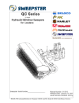
51-4005, 11/12 1 WLA Series 213 Model Hydraulic Windrow Sweepers for Loaders Sweepster Serial Number____________________ Manual Number: 51-4005 Release Date: November 2012 Serial Number 0733001 and Up 800-456-7100 www.paladinlcg.com Sweepster 2800 N. Zeeb Rd., Dexter, MI 48130 United States of America Copyright © 2 51-4005, 11/12 51-4005, 11/12 3 Table of Contents Section 1 ... Installation.................................................... 5-13 Section 2 ... Operation and Maintenance...................... 15-22 Section 3 ... Service......................................................... 23-33 Section 4 ... Parts............................................................ 35-46 Section 5 ... Options........................................................ 47-55 Section 6 ... Appendix..................................................... 57-61 4 51-4005, 11/12 51-4005, 11/12 5 Installation Manual Table of Contents Introduction................................................................ 6 Safety Information.................................................7-13 General Safety Information.....................................7-8 Safety Signs & Labels......................................... 10-11 Product Information Section..................................... 12 Installation/Storage.................................................. 13 6 51-4005, 11/12 SAFETY SECTION INTRODUCTION Introduction Contacting SWEEPSTER Importance of this Manual If you have any questions about information in this manual or need to order parts, please call, write, fax or e-mail SWEEPSTER. Read this manual before attempting to operate the equipment. This operator’s manual should be regarded as part of the sweeper. Suppliers of both new and secondhand sweepers are advised to keep documentation indicating that this manual was provided with the sweeper. The manual contains information regarding installation, operation and maintenance required for this sweeper and optional equipment. It also includes detailed parts lists. Purpose of Sweeper This sweeper is designed solely for use in construction cleanup, road maintenance, grounds maintenance and similar operations. Use in any other way is considered contrary to the intended use. Compliance with and strict adherence to operation, service and repair conditions, as specified by the manufacturer, are also essential elements of the intended use. This sweeper should be operated, serviced and repaired only by persons who are familiar with its characteristics and acquainted with relevant safety procedures. Accident prevention regulations, all other generally recognized safety regulations and all road traffic regulations must be observed at all times. Any modifications made to this sweeper may relieve the manufacturer of liability for any resulting damage or injury. SWEEPSTER 2800 North Zeeb Road Dexter, Michigan 48130 Phone: (734) 996-9116 - (800) 456-7100 FAX: (734) 996-9014 e-mail: [email protected] For help with installation, operation or maintenance procedures, contact our Technical Service Department. Direct product questions and parts orders to our Sales Department. When ordering parts or accessories, be prepared to give the following information: •Sweeper model, serial number and date of purchase •Prime mover, make and model •Part number, description and quantity Terms Used in Manual Right-hand, left-hand, front and rear are determined from the operator’s perspective (either the operator’s seat or standing behind a walk-behind unit), facing forward in the normal operating position. Prime mover refers to the tractor, truck, loader or tow vehicle that the sweeper is mounted on or towed by. Safety Alert Symbol Optional Equipment This safety alert symbol indicates important safety messages in this manual. When you see this symbol, be alert to the possibility of injury. Carefully read the message that follows and inform other operators. Installation instructions for optional equipment, if applicable, appear in the Service Manual Section. Specifications & Features Due to continuous product improvement, specifications and features may change without notice. Warranty To validate the warranty for this unit, fill out the warranty card or warranty pages located at the back of this manual. Then, send this information to SWEEPSTER. 51-4005, 11/12 7 SAFETY SECTION GENERAL SAFETY INFORMATION Safety Information Read this manual Read all safety information in this manual. All operators must read and understand the entire contents of this manual before sweeping. General safety practices are listed on Safety Information pages and specific safety information is located throughout this manual. Hazard Definitions Four hazard classifications are used in this manual. They are DANGER - Indicates an imminently hazardous situation which, if not avoided, will result in death or serious injury. WARNING -Indicates a potentially hazardous situation which, if not avoided, could result in death or serious injury. •Check prime mover tire pressure before sweeping. •Check tire ratings to be sure they match the prime mover load. Weigh the sweeper end of the prime mover, if necessary, to insure proper tire rating. • Remove from the sweeping area all property that could be damaged by flying debris. • Be sure all persons not operating the sweeper are clear of the sweeper discharge area. • Always wear proper apparel such as a long-sleeved shirt buttoned at the cuffs; safety glasses, goggles or a face shield; ear protection; and a dust mask. While operating sweeper: • When operating sweeper, adhere to all government rules, local laws and other professional guidelines for your sweeping application. WARNING Never raise the sweeper more than a few feet off the ground. The sweeper can tip back or the prime mover can tip over causing death or serious injury, CAUTION -Indicates a potentially hazardous situation which, if not avoided, may result in minor or moderate injury. • Before leaving the operator’s area for any reason, lower the sweeper to the ground. Stop the prime mover engine, set the parking brake and remove the key from the ignition. NOTICE - Used for instructions when machine damage may be involved. • Minimize flying debris - use the slowest rotating speed that will do the job. See Operation Section: Operating Tips Operation • Keep hands, feet, hair and loose clothing away from all moving parts. CAUTION - A sweeper is a demanding machine. Only fully trained operators or trainee operators under the close supervision of a fully trained person should use this machine. Before operating sweeper: • Leave the brush hood (shield) and all other shields and safety equipment in place when operating the sweeper and prime mover. • Be aware of the extra weight and width a sweeper adds. Reduce travel speed accordingly. See Product Information Section: Operating the Sweeper. •Learn sweeper and prime mover controls in an off-road location. • When sweeping on rough terrain, reduce speed to avoid “bouncing” the sweeper. Loss of steering can result. •Be sure that you are in a safe area, away from traffic or other hazards. • Never sweep toward people, buildings, vehicles or other objects that can be damaged by flying debris. •Check all hardware holding the sweeper to the prime mover, making sure it is tight. •Replace any damaged or fatigued hardware with properly rated fasteners. See Maintenance Section •Make sure all hydraulic hardware and hydraulic fittings are tight. •Only operate the sweeper while you are in the operating position. The safety restraint must be fastened while you operate the prime mover. Only operate the controls while the engine is running. Protective glasses must be worn while you operate the prime mover and while you operate the sweeper. •Replace any damaged or fatigued fittings or hoses. • While you operate the sweeper slowly in an open area, check for proper operation of all controls and all protective devices. Note any needed repairs during operation of the sweeper. Report any needed repairs. 8 51-4005, 11/12 SAFETY SECTION GENERAL SAFETY INFORMATION Service & Repair - General CAUTION - Do not modify the sweeper in any way. Personal injury could result. If you have questions, contact your dealer or SWEEPSTER. WARNING! Repair or adjust the sweeper in a safe area, away from traffic and other hazards. Before adjusting or servicing - lower the sweeper to the ground, set parking brake, shut down the prime mover and remove the key from the ignition. When working on or around the sweeper, safely secure it from falling or shifting. WARNING! Service & Repair - Hydraulic Safety Stop the prime mover engine and release hydraulic pressure before servicing or adjusting sweeper hydraulic systems. WARNING - Escaping hydraulic fluid can have enough pressure to penetrate the skin, causing serious personal injury. Check lines, tubes and hoses carefully. Do not use your hand to check for leaks. Use a board or cardboard to check for leaks. Tighten all connections to the recommended torque. See Appendix. Do not bend high pressure lines. Do not strike high pressure lines, Do not install bent lines, bent tubes, or kinked hoses. Do not install damaged lines, damaged tubes, or damaged hoses. Repair loose lines, loose tubes, and loose hoses. Repair damaged lines, damaged tubes, and damaged hoses. Leaks can cause fires. See your SWEEPSTER dealer for repair or replacement parts. Replace the parts if any of the following conditions are present: •The end fittings are damaged or leaking. •The outer covering is chafed or cut. •The reinforcing wire layer is exposed. •The outer covering is ballooning locally. •The hose is kinked or crushed. •The hoses have been pulled or stretched. Make sure that all clamps, guards, and shields are installed correctly. EXPOSURE TO RESPIRABLE CRYSTALLINE SILICA DUST ALONG WITH OTHER HAZARDOUS DUSTS MAY CAUSE SERIOUS OR FATAL RESPIRATORY DISEASE. It is recommended to use dust suppression, dust collection and if necessary personal protective equipment during the operation of any attachment that may cause high levels of dust. REMOVE PAINT BEFORE WELDING OR HEATING. Hazardous fumes/dust can be generated when paint is heated by welding, soldering or using a torch. Do all work outside or in a well ventilated area and dispose of paint and solvent properly. Remove paint before welding or heating. When sanding or grinding paint, avoid breathing the dust. Wear an approved respirator. If you use solvent or paint stripper, remove stripper with soap and water before welding. Remove solvent or paint stripper containers and other flammable material from area. Allow fumes to disperse at least 15 minutes before welding or heating. 51-4005, 11/12 9 Notes 10 51-4005, 11/12 SAFETY SECTION SAFETY SIGNS & LABELS Safety Signs and Labels There are several specific safety signs on this sweeper. The exact location of the hazards and the description of the hazards are reviewed in this section. Placement or Replacement of Safety Signs Instructions 1. Clean the area of application with nonflammable solvent, and then wash the same area with soap and water. 2. Allow the surface to fully dry. 3. Remove the backing from the safety sign, exposing the adhesive surface. 4. Apply the safety sign to the position shown in the diagram above and smooth out any bubbles. • • • Keep all safety signs clean and legible. Replace all missing, illegible, or damaged safety signs. Replacement parts, for parts with safety signs attached, must also have safety signs attached. • Safety signs are available, free of charge, from your dealer or from SWEEPSTER. Serial Number Tag ItemPart 4. 8. 9. 10. 11. 12. 13. 41043 50-0643 50-0721 50-0722 50-0724 50-0726 50-0775 QtyDescription 1 2 2 1 1 2 2 Decal, Warning, Hazardous Dust Label, Tie Down Point Label, Warning, Crush Hazard Label, Warning, Misuse Hazard Label, Warning, High Pressure Fluid Hazard Label, Warning, Flying Objects & Entanglement Label, Warning, Crush Hazard Vertical 51-4005, 11/12 11 SAFETY SECTION SAFETY SIGNS AND LABELS Safety Signs and Labels 8. 4. 50-0643 41043 Serial Number Tag 10. 9. 50-0721 11. 50-0724 50-0722 12. 50-0726 13. 50-0775 12 51-4005, 11/12 OPERATION SECTION PRODUCT SPECIFICATIONS Product Information Section Specifications and Model Views Maximum Width at 0° Articulation Maximum Length at 0° Articulation Maximum Width at Full Articulation Maximum Length at Full Articulation Range of Hydraulic Oil Flow and Pressure Dual Motor 11.9 CI 12-30 gpm 4500 max psi Dual Motor 11.9/23.9 CI 18-45 gpm 4000 max psi Dual Motor 23.9 CI 24-60 gpm 4000 max psi Maximum Allowable Back Pressure 750psi @ 250rpm Over 750psi - case drain required 51-4005, 11/12 13 INSTALLATION SECTION INSTALLING/REMOVING SWEEPER & STORAGE Sweeper Installation (Broom to Prime Mover) Removing the Sweeper WARNING - Serious injury or death may result from disengaging the sweeper when the sweeper is in an unstable position or carrying a load. Place the sweeper in a stable position before disengaging. WARNING - Improper attachment of sweeper could result in injury or death. Do not operate this machine until you have positive indication that the attachment is securely mounted. 1. Position the broom on a level surface. 2. Enter the prime mover. 3. Fasten the safety restraints. 4. Start the engine. 5. Disengage the parking brake. 6. Align the attachment mechanism with the mounting on the broom, attach to the prime mover. Follow the attaching procedure in the prime mover owners manual. 7. Engage the parking brake and shut down the prime mover. Be sure to relieve pressure to the auxiliary hydraulic lines. 8. Unfasten safety restraints and exit the prime mover. 9. Lock jack stands in stowed position. (if available) 10. Ensure that the hydraulic quick couplers are clean. Connect hydraulic lines for the broom to the prime mover. Twist the collar of the quick couplers one quarter of a turn in order to secure the hydraulic connections. 11. While the loader arms are lowered, visually inspect the attachment mechanism to ensure that it is securely mounted. 12. Enter prime mover, fasten safety restraints and start the prime mover. 13. Carefully raise the loader and cycle the rollback/dump cylinders to check clearances, that limiting stops make proper contact and verify that all mounting procedures have been successfully completed. Contact SWEEPSTER for instructions if the limiting stops do not contact properly. NOTICE - Hoses for the sweepers must be removed before the quick attach is disengaged. Pulling the sweeper with the hoses could result in damage to the prime mover or the sweeper. 1. Lower the broom to the ground. 2. Engage the parking brake and shut down the prime mover. Be sure to relieve pressure to the auxiliary hydraulic lines. 3. Unfasten safety restraints and exit prime mover. 4.Lock jack stands in lowered position. (if available) 5. Disconnect the broom hydraulic lines from the prime mover. Connect quick couplers together to keep clean. 6. Disengage attachment locking mechanism. (mechanical type) 7. Enter prime mover, fasten safety restraints and start the prime mover. 8. Disengage attachment mechanism. (hydraulic type) 9. Disengage the parking brake, and back away from the broom. Storage NOTICE - Do not store the sweeper with weight on the brush. Weight will deform the bristles, destroying the sweeping effectiveness. To avoid this problem, place the sweeper on blocks or use storage stands. Do not store polypropylene brushes in direct sunlight. The material can deteriorate and crumble before the bristles are worn out. Keep polypropylene brush material away from intense heat or flame. 14 51-4005, 11/12 Notes 51-4005, 11/12 15 Operation and Maintenance Manual Table of Contents Operation..............................................................16-17 Operation .........................................................................16 Leveling Sweeper..............................................................17 Maintenance.........................................................18-22 Brush Pattern Adjustment..................................................18 Maintenance Schedule......................................................19 Maintenance Record..........................................................20 Replacing Brush Sections..................................................21 Lubrication Points............................................................. 22 16 51-4005, 11/12 OPERATION SECTION SWEEPING/OPERATING TIPS Before Each Use Perform daily maintenance as indicated in Maintenance Schedule. Run the prime mover and sweeper at a slow idle. Check for hydraulic leaks or other problems and make corrections, if necessary, before using the sweeper. See “Hydraulic inspection guideline” . WARNING - Avoid serious injury. Check for large objects that could harm the operator or others if thrown by the sweeper. Remove these items before operating. During Use Directing Debris Carry the sweeper low to the ground so that the operator has good visibility and stability. Avoid any sudden movements. Avoid excessive downward pressure on the brush sections to prevent excessive wear. A two to four inch wide pattern is sufficient for most applications. Ensure that the adjustment bolts are equally adjusted in order to prevent an uneven wear pattern. To adjust brush pattern see “Adjusting Brush Pattern”. Direct debris by angling the brush head in that direction. Observe wind direction. Sweeping with the wind makes sweeping more effective and helps keep debris off the operator. The terms swing and angle are used interchangeably. Manual Angle 1. Remove the lock pin from links. 2. Position the brush head at the desired angle, aligning holes in the inner and outer link. 3. Insert and close the lock pin. Hydraulic Angle 1. Start the prime mover. 2. Position the brush head at the desired angle by using the valve control for the swing function. 4. Engage the brush and then lower it to the ground. 5. Increase prime mover engine rpm to sweeping speed. 6. Travel forward at 5 mph (8 kph) or less. NOTICE - Avoid sweeper damage. Reduce travel speed to avoid hitting immovable objects. Operating Tips NOTICE - Avoid sweeper damage. Do not ram into piles. Use an appropriate attachment for this type of job. Brush, Engine & Travel Speeds Vary brush, engine and travel speeds to match sweeping conditions. Large Areas When sweeping a large area, such as a parking lot, make a path down the middle and sweep to both sides. This reduces the amount of debris that the sweeper must sweep to one side. Snow Fast brush speeds and slow travel speeds are needed to sweep snow effectively. Start at 3/4 throttle and the lowest gear of the prime mover. For wet and/or deep snow, increase to almost full throttle. This helps keep snow from packing up inside the brush hood. In deep snow you may need to make multiple passes to get down to a clean surface. To keep snow from blowing back onto a swept area, always sweep so the wind is at your back. Dirt & Gravel To keep dust at a minimum, use the optional dust suppression kit or plan sweeping for days when it is overcast and humid or after it has rained. Also, sweep so the wind blows at your back. Low brush speeds and moderate travel speeds work best for cleaning debris from hard surfaces. Brush speeds that are too fast tend to raise dust because of the aggressive sweeper action. Sweeping To sweep gravel, use just enough brush speed to “roll” the gravel, not throw it. To sweep: Heavy Debris 1. Manual angle only - Swing the brush head assembly the direction that you want to direct debris. Travel slowly - 2-3 mph. (3-5 kph) 2. Start the prime mover at idle and raise the brush. 3. Hydraulic angle only - Swing the brush head assembly the direction that you want to direct debris. Sweep a path less than the full width of the sweeper. Increase engine speed if debris becomes very heavy. 51-4005, 11/12 17 OPERATION SECTION LEVELING THE SWEEPER Aligning Mounting The mounting incorporates a four-bar linkage system that allows the sweeper to move up and down independently of the loader arms. This feature is very important because it permits the sweeper to follow the contours of the ground, offering a good sweep. NOTICE - Adjust the four-bar linkage before each operation to avoid sweeper damage. Sweeping with a properly adjusted mounting offers efficient performance, while using the mounting out of adjustment can cause severe damage to the sweeper and can result in a poor sweep. If the U-channels on the loader arms are positioned too low, the sweeper must support the loader arms, an amount of weight far greater than the sweeper is designed to carry. If the U-channels on the loader arms are too high, the sweeper cannot sweep into the low areas. figure 1 To adjust the mounting: 1. Drive the loader and sweeper to a flat surface. 2. Lower the sweeper so the casters sit on the ground. 3. Adjust the loader arms so the tops of the U-channels on the sweeper and the tops of the U-channels on the loader arms are even (figure 1). 4. Adjust the brush height according to Setting Brush Pattern. Leveling Level the sweeper for even brush wear and effective use. CAUTION - Avoid injury. Before adjusting the sweeper, always turn off the sweeper and the prime mover engine and remove the key. figure 2 1. Move the sweeper to a flat, paved surface. 2. Lower the brush head assembly to the ground. 3. Position the brush head assembly straight ahead. 4. Engage the parking brake and shut down the prime mover. Be sure to relieve pressure to the auxiliary hydraulic lines. 5. Unfasten safety restraints and exit prime mover. 6. On each side, measure from the brush frame to the ground (figure 2). If measurements are not equal: Loosen hardware that attaches the swing assembly to the brush head assembly; lower the high side of the brush head until both sides are an equal distance above the ground. Tighten the hardware. (figure 3) figure 3 18 51-4005, 11/12 MAINTENANCE SECTION BRUSH PATTERN/SPRING CHAIN/TRANSPORT CHAIN Setting Brush Pattern A properly adjusted brush offers the best sweeper performance. To check the brush pattern: 1. Move the sweeper to a dusty, flat surface. 2. Engage the parking brake and shut down the prime mover. Be sure to relieve pressure to the auxiliary hydraulic lines. 3. Ratchet the brush head down until the bristles touch the ground. 4. Start the sweeper at a slow speed. Run the sweeper in a stationary position for 10 seconds. 5. Raise the sweeper and back away; switch off the engine and remove the key. The brush pattern left in the dust should be 2-4 inches (51-102 mm) wide, running the length of the brush. (Compare the swept area with figure 7.) 6. Adjust the brush pattern as necessary using the adjusting ratchet. Swept Area 2-4 in. (51-102 mm) Figure 7 51-4005, 11/12 19 MAINTENANCE SECTION MAINTENANCE SCHEDULE Maintenance Schedule Procedure Brush head assembly - Level Brush pattern - Check (See Pattern Adj. Section) Cylinders - Retract rods - Grease threaded and ball ends to prevent rust Filter, air, prime mover - Clean Fittings/hoses, hydraulic - Check for leaks/tighten Check for damage Fittings, zerk - Grease. (See lubrication points) Oil, hydraulic - Check Level Hardware - Check for tightness Before Each Use After Each Use 100 Hours 500 Hours See Prime Mover 20 51-4005, 11/12 MAINTENANCE SECTION MAINTENANCE RECORDS Maintenance Record Use this log to record maintenance performed on the sweeper. Date Maintenance Procedure Performed Performed By Comments 51-4005, 11/12 21 MAINTENANCE SECTION REPLACING BRUSH SECTIONS 1. Remove lynch pins and bushings. Retain hardware for reinstallation. Remove motor. 2. Remove core from brush head assembly. 3. Remove lynch pins, bushings and motor from the other side of brush head. 4. Remove idler bearing shaft mounting plate, retaining hardware. 5. Remove second core from brush head assembly. 6. Remove old sections. figure 1 7. Install new sections by doing the following: a. Slide the first section onto the core with the drive pins on each side of a tube. Make sure that the drive pins angle up. (figure 1) b. Install a second section with drive pins rotated 180° from those on the first section. (figure 2) c. Continue installing sections, rotating each section 180° until the core is full. figure 2 8. Re-attach the section retainer with previously removed hardware. 9. Lay cores on ground. Lower frame over cores. 10.Re-attach idler bearing mounting plate with previously removed hardware. 11.Re-attach motors with lynch pins and bushings. Worn Section Standard Section OD, Ring ID New 24 26 32 36 36 46 6.38 8.00 10.00 10.00 10.63 19.38 Reference Information Section OD, Worn Exposed Bristle, Worn Bristle Length Exposed Bristle, New 17 18 22 24 25 34 3.8 4.0 5.0 6.0 6.0 6.0 8.50 9.00 11.00 13.00 12.69 13.31 7.5 8.0 10.0 12.0 11.4 12.1 22 51-4005, 11/12 MAINTENANCE SECTION LUBRICATION POINTS Lubrication Points The following grease fittings should be greased before each use. See figure for locations. 1. Parallel Link Pins (8 fittings) 2. Caster Assembly (2 fittings) 3. Hydraulic Angle Cylinder (1 fitting) Not Shown: Center Mounted (1 fitting) 3 1 1 2 51-4005, 11/12 23 Service Manual Table of Contents Troubleshooting .................................................23-33 Brush Head........................................................................24 Lift & Swing........................................................................25 Hydraulic System..........................................................26-29 Wiring Harness........................................................... 30--33 24 51-4005, 11/12 SERVICE SECTION TROUBLESHOOTING Brush Head Problem Possible Cause Possible Solution Brush rotates wrong direction Hoses installed incorrectly Switch hoses at brush head tubes Brush slows or stops when sweeping Brush pattern too wide Adjust brush pattern to 2-4 inches (51-101mm) wide: see Maintenance: Adjusting Brush Pattern Travel speed too fast Travel no more than 5 mph (8 kph) while sweeping (2-3 mph recommended) Trying to sweep too much material at once Make several passes with sweeper Relief pressure set too low Set relief pressure to 2000 psi (138.0 bars) Filter plugging Change or clean filter Brush wears into cone shape Tires on prime mover at different pressures or are different sizes Check tire sizes and ratings: make corrections as necessary Brush wears very quickly Brush pattern too wide Adjust brush pattern to 2-4 inches (51-101mm) wide: see Maintenance: Setting Brush Pattern 51-4005, 11/12 25 SERVICE SECTION TROUBLESHOOTING Hydraulic Cylinders - Lift & Swing Problem Hydraulic cylinder neither extends nor retracts Hydraulic cylinder only extends or only retracts Possible Cause Possible Solution No power from controls because wires are broken or disconnected Reconnect wires if disconnected; replace wires if broken No power from controls because switch is broken Replace switch Hoses or fittings loose or disconnected Tighten hoses or fittings Restriction in hoses Remove bends in hoses, remove obstructions inside hoses Dirt or debris in spools Contact Sweepster Technical Service 26 51-4005, 11/12 SERVICE SECTION TROUBLESHOOTING Hydraulic System Problem Hydraulic system overheats Hydraulic motor seals leak Possible Cause Possible Solution Restriction in hoses Remove bends in hoses; remove obstructions inside hoses Host pump flow rate exceeds maximum rate of broom Contact host manufacturer for proper flow control method Back pressure exceeds 1000psi Contact Sweepster Motor is failing High number of hours on motor; Contact dealer to rebuild or replace Motor Port Identification PRESSURE RETURN RETURN PRESSURE RETURN PRESSURE 51-4005, 11/12 27 SERVICE SECTION TROUBLESHOOTING 03-5215 12 Volt Manifold A Hydraulic Schematic B P T P T 28 51-4005, 11/12 SERVICE SECTION TROUBLESHOOTING 03-5835 12 Volt Manifold Hydraulic Schematic B A 3 .082 2 P 1 10 T P HYDRAULIC SCHEMATIC 213 SERIES T 51-4005, 11/12 29 SERVICE SECTION TROUBLESHOOTING 03-5836 24 Volt Manifold Hydraulic Schematic B A 3 .082 2 2 P 1 0 10 T T T P HYDRAULIC SCHEMATIC 213 SERIES T M TO APPLICATION SERVICE SECTION TROUBLESHOOTING TO H G F E A B C D E B C D A F H G TO VIEW "A-A" APPLICATION LAF9444 WIRE PLUGHARNESS - A, D, E, G & H IDENTIFICATION FROM PLUG - A, D, E, G & H B C D FROM BATTERY + POSITIVE BATTERY NEGATIVE- 1.0 A A APPLICATION TO BATTERY + POSITIVE TO A A A B C D FROM E B C D A F Description Circuit Breaker Switch Rubber Boot A 1.0 BATTERY NEGATIVE- BATTERY + POSITIVE VIEW "A-A" PLUG - A, D, E, G & H H G Part Qty 07-3152 1 07-0868 1 07-1824 1 TO APPLICATION LAF9444 WIRE HARNESS IDENTIFICATION F E H G Item 1. 2. 3. A A 1.0 BATTERY NEGATIVE- BATTERY + POSITIVE VIEW "A-A" PLUG - A, D, E, G & H CONTROL OUT C B TO APPLICATION CONTROL OUT LAF9441 WIRE HARNESSA FROM D A A,D,E,G,H PLUG F H E G E B C D A F H G PLUG - A, D, E, G & H C B A A 1.0 BATTERY NEGATIVE- BATTERY + POSITIVE VIEW "A-A" CONTROL OUT A,D,E,G,H PLUG D A F H E G 2 B A A,D,E,G,H PLUG A B A B APPLICATION B H 1.0 1.0 BATTERY NEGATIVE- APPLICATION CONTROL OUT G D C IDENTIFICATION LAF9444 WIRE HARNESS VIEW "A-A" IDENTIFICATION F E A CONTROL OUT H G PLUG - A, D, E, G & H FROM LAF9441 VIEW "A-A" WIRE HARNESS IDENTIFICATION BATTERY + POSITIVE F BATTERY A,D,E,G,H PLUG NEGATIVE- E A A,D,E,G,H PLUG LAF9441 WIRE HARNESS IDENTIFICATION B APPLICATION TO A ROM A APPLICATION TO Wiring Harness 41 WIRE HARNESS FROM 441 WIRE HARNESS SS ROM APPLICATION 4 WIRE HARNESS WIRE HARNESS 51-4005, 11/12 30 1 3 2 1A WIRE NO. 1A 1B 2 1A 0.38 PACKARD PIN B BATTERY (-) BLACK 12 - PACKARD PIN A 0.38 SIZE ULTRA SONIC SPLICE TO RED 12 APPLICATION ULTRA SONIC SPLICE FROM BATTERY (+) RED GUAGE 12 IDENTIFICATION WIRE 1B NO X X X YES - EXTRA WIDE PROTECTION - - - SIZE 1 WIRE TO BE TYPE GXL RING TERMINAL (WAYTEK # 32205) ULTRA SONIC SPLICE RING TERMINAL (WAYTEK # 32205) TYPE TERMINAL END (LEFT) (BEYOND HARNESS) PACKARD 12129493 & SEAL PACKARD 12129493 & SEAL ULTRA SONIC SPLICE TYPE TERMINAL END (LEFT) (BEYOND HARNESS) - - - YES X X X NO EXTRA WIDE PROTECTION WIRE NO. 1A 1B 2 B A 2 1B 51-4005, 11/12 31 SERVICE SECTION TROUBLESHOOTING Wiring Harness 51-4005, 11/12 32 SERVICE SECTION TROUBLESHOOTING 1 2 3 4 WIRE NO. 16 16 16 16 GUAGE 1 2 WIRE F E A B C D A B 1 SIZE - 3 4 TERMINAL END (LEFT) (BEYOND HARNESS) EXTRA WIDE PROTECTION NO YES X X X X SIZE 0.25 0.25 0.25 EXTRA WIDE PROTECTION YES NO X X X X - END (RIGHT) (BEYOND HARNESS) TERMINAL TYPE PACKARD 12048074 & SEAL SPADE TERMINAL (FEMALE) SPADE TERMINAL (FEMALE) SPADE TERMINAL (FEMALE) FLANGE W/ SLOT FOR VELCRO MOUNTING STRAP BRAID OVER WIRES TYPE PACKARD 12048159 & SEAL PACKARD 12048159 & SEAL PACKARD 12048074 & SEAL PACKARD 12048074 & SEAL 2 VIEW B-B B A C WIRE TO BE TYPE GXL TO PACKARD PIN A (2-PIN) SWITCH 1-A SWITCH 1-B SWITCH 1-C APPLICATION 3 4 FROM IDENTIFICATION PACKARD PIN F (8-PIN) PACKARD PIN B (2-PIN) PACKARD PIN B (8-PIN) PACKARD PIN C (8-PIN) BLACK RED RED YELLOW 1 H PLUG - A,D,E,G, & H VIEW A-A G POWER IN CONTROL OUT Wiring Harness 1 2 3 4 WIRE NO. B B 1 SWITCH MOTION 2 DO NOT USE A NUT ON THE OUTSIDE OF CONTROL BOX BETWEEN THE SWITCH BOOT AND BOX. VIEW A-A RED YELLOW 16 16 3 PACKARD 12045773 & SEAL - DEUTSCH 2 PIN A PACKARD PIN C A 1 WIRE TO BE TYPE GXL 1A PACKARD 12045773 & SEAL - DEUTSCH 1 PIN A PACKARD PIN B BRAID OVER WIRES ULTRA SONIC SPLICE - DEUTSCH 2 PIN B ULTRA SONIC SPLICE A ULTRA SONIC SPLICE - PACKARD 12045773 & SEAL DEUTSCH 1 PIN B - TYPE TERMINAL ULTRA SONIC SPLICE ULTRA SONIC SPLICE SIZE 1B - - - X X X X X - NO 1C EXTRA WIDE PROTECTION YES - - - - - SIZE DEUTSCH 0462-201-16141 & SEAL DEUTSCH 0462-201-16141 & SEAL DEUTSCH 0462-201-16141 & SEAL DEUTSCH 0462-201-16141 & SEAL ULTRA SONIC SPLICE TYPE TERMINAL - - - - - X X X X X NO EXTRA WIDE PROTECTION YES A PLUG A,D,E,G, & H D E BLACK 16 2 BLACK 16 PACKARD PIN F TO APPLICATION END (RIGHT) (BEYOND HARNESS) B 1A B C F A H BLACK GAUGE 16 FROM END (LEFT) (BEYOND HARNESS) A G WIRE NO. 1A 1B 1C 2 3 IDENTIFICATION WIRE WIRE NO. 1A 1B 1C 2 3 1C 3 1B 2 51-4005, 11/12 33 SERVICE SECTION TROUBLESHOOTING Wiring Harness B 34 51-4005, 11/12 Notes 51-4005, 11/12 35 Parts Manual Table of Contents Parts Lists......................................................................35-45 Brush Head Frames...........................................................36 Core Assemblies................................................................37 Motor Assembly.................................................................38 Hydraulic Assembly...........................................................39 Manual Assembly...............................................................40 Swing Mountings..........................................................41-44 Brush Head Labels............................................................45 Brush Head Stand.............................................................46 36 51-4005, 11/12 PARTS SECTION BRUSH HEAD FRAME Brush Head Frame 2 12 19 3 11 3 18 4 16 9 7 1 17 14 15 10 4 13 22 7 2 8 5 6 NOTE: 1. ASSEMBLE ITEM 20 WITH CROSS HOLES HORIZONTAL. 20 21 Item Part QtyDescription Item Part Qty 1. 2. 3. 4. 5. 6. 7. 8. 9. 10. 11. 1 30 50 8 8 8 8 8 1 1 1 12. 13. 14. 15. 16. 17. 18. 20. 21. 22. 2 Sheet, Hood, 5 Ft 2 Sheet, Hood, 6 Ft 1 Weld, Brush Frame, 10 Ft 1 Weld, Brush Frame, 12 Ft 2 Pin, 1 1/4 x 3.25, with Holes 1 Weld, Plate, Middle 2 Plate, Mounting, Middle 1 Plate, Mounting, Brush Head, Pivot 1 Sheet, Hood Filler 8 Pin, with Shoulder 12 Pin, Lynch, 1/4 4 Nut, Rivet, 5/16-18, .150-.312 Grip 07-2032 07-2952 07-3617 07-3760 07-4227 07-4228 07-4610 07-6026 13-11195 13-14077 13-14078 Clevis, Double Link, Gr80, 9/32 Screw, HFH, CL10.9, M6-1 x 20 Nut, Insert, Hex, M6 x 1 Screw, HHC, CL10.9, M12-1.75 x 40mm Washer, Lock, Split, M14 Washer, Flat, CL8.8, M14 Nut, Hex, Lock, CL10.9, M12-1.75 Screw, HHC, CL10.9, M14-2 x 50 mm Chain, 3/8, 26 Links Sheet, Hood, Side, Left Sheet, Hood, Side, Right 13-14817 13-14079 13-14550-10 13-14550-12 13-14787 13-14812 13-14814 13-14815 13-14816 13-16403 RHW8068 RHW8642 Description 51-4005, 11/12 37 PARTS SECTION CORE ASSEMBLIES Core Assemblies 2 9 14 10 13 3 DETAIL B 4 6 A 12 4 5 1 8 7 5 4 11 DETAIL A B 01-1211-10 Set, Section, 36, Mixed, 10 ft 01-1211-12 Set, Section, 36, Mixed, 12 ft 01-1212-10 Set, Section, 36, Poly, 10 ft 01-1212-12 Set, Section, 36, Poly, 12 ft Item Part 1. 2. 3. 4. 5. 6. 7. 8. 9. 10. 11. 12. 13. 14. Qty Description 07-3279 4 07-3617 8 07-3731 8 07-3747 28 07-3749 16 07-3752 12 07-6056 4 07-6866 1 13-12738 2 13-13166 2 13-14805 1 13-14808 1 13-15866-5 2 13-15866-6 2 13-16225 2 Washer, Flat, Gr8, 3/8 Nut, Insert, Hex, M6 x 1 Screw, HHC, CL10.9, M6-1 x 30mm Washer, Lock, Split, Medium, M10 Screw, HHC, CL10.9, M10-1.5 x 30mm Screw, HHC, CL10.9, M10-1.5 x 45mm Nut, Flange, M10-1.5 Bearing, 1 1/2 Square, 4 Bolt Plate, Hex, Hub, 5.25 Plate, Ring, Core, End Weld, Square Shaft, 1 1/2, Core Weld, Hub, Square, 1 1/2, with Doublers Weld, Core, 10, 5 Ft Weld, Core, 10, 6 Ft Plate, Reciever, Hex, 2.5 38 51-4005, 11/12 PARTS SECTION MOTOR ASSEMBLY Motor Assembly Hydraulic Motor Requirements Model 21319 and 21343 Require 2 03-4430 Model 21321 and 21344 Require 1 03-4430 (Right) and 1 03-5192 (Left) Model 21321 and 21345 Require 2 03-5192 ItemPart 1. 2. 3. 4. 5. 6. 7. 8. QtyDescription 03-2035 2 Fitting, 12MF-16MB See Above Chart 07-4227 4 Washer, Lock, Split, M14 07-7008 4 Screw, HHC, CL10.9, M14-2.0 x 55mm 07-7009 4 Nut, Hex, CL8.8, M14-2.0 13-15145 1 Plate, Mounting, Motor, Eaton 13-15149 4 Tube, Round, 1 1/2 x 1.06 x 4.25 13-15208 1 Hub, Hex, Drive Replacement Parts for 03-4430 : 03-5043 Front, Seal Kit 03-5659 Rear, Seal Kit 03-5660 Complete, Seal Kit Replacement Parts for 03-5192 : 03-5663 Front, Seal Kit 03-5664 Rear, Seal Kit Must Order Both for Complete 51-4005, 11/12 39 PARTS SECTION HYDRAULIC ASSEMBLY Hydraulic Assembly RETURN TOP PORT ON MOTOR 15 PRESSURE BTM PORT ON MOTOR 14 7 15 12 4 5 14 3 DETAIL A 2 13 1 8 30 25 CASE DRAIN 38 27 A 34 36 19 DIRECTION OF FLOW 14 15 18 30 35 17 28 20 40 39 10 23 32 29 2 3 31 24 33 32 1. 2. 3. 4. 5. 7. 8. 9. 10. 11. 12. 13. 14. 15. 16. 17. 18. 19. 20. 23. 24. 03-1945 03-2092 03-2291 03-3344 03-3779 03-4183 03-5160 03-5207 03-5212 03-5218 03-5235 03-5246 03-5236 03-5237 03-4119 03-5238 03-5248 03-5239 03-5241 03-5242 03-5243 03-5244 03-5494 03-4887 03-5724 PRESSURE BTM PORT ON MOTOR 37 26 27 11 9 15 16 Replacement Parts for 03-5724: 45617 Seal Kit 104605 Cylinder Rod Item Part RETURN TOP PORT ON MOTOR 14 Qty Description 1 Fitting, Adapter, HP, 1 1/16MOR, 3/4MFS 2 Fitting, Elbow, HP, 90°, 9/16MOR, 3/8MFS 2 Fitting, Adapter, HP, 3/8MFS, 9/16MOR 1 Fitting, Adapter, HP, 7/16MOR, 1/4MFS 1 Fitting, Adapter, HP, 1 1/16MOR, /4FFS 1 Fitting, Cross, 3/4MFS, All Ends 1 Tee, 12MF-12MF-12MF 4 Hose, Cradle 1 Fitting, Reducer, 12FFS, 4MFS 4 Cover, Plate 1 Hose, 1/4 x 84, TC, 4FFS, 4FFS45, 10ft 1 Hose, 1/4 x 96, TC, 4FFS, 4FFS45, 12ft 1 Hose, 3/8 x 42, TC, 6FFS, 6FFS90 2 Hose, 3/4 x 90, TC, 12FFS, 12FFS, 10ft 2 Hose, 3/4 x 102 TC, 12FFS, 12FFS, 12ft 2 Hose, 3/4 x 82, TC, 12FFS, 12FFS45, 10ft 2 Hose, 3/4 x 94, TC, 12FFS, 12FFS45, 12ft 1 Hose, 3/8 x 32, TC, 6FFS, 6FFS45 2 Hose, 1 x 120, TC, 16FFS, 12FFS90 1 Hose, Cradle 1 Cover, Plate 1 Weld, Plate 1 Fitting, 12FF, 12FF 1 Cylinder, 2.5 x 7.5 (09/23/09 & Before) 1 Cylinder, 2.5 x 1.38 x 7.5, 3.5K (9/24/09 & After) 25. 03-5215 1Manifold, Swing, 12 Volt (1018999 & Down) 03-5835 1 Manifold, Swing, 12 Volt (1019200 & Up) 03-5280 1 Manifold, Swing, 24 Volt (1018999 & Down) 03-5836 1 Manifold, Swing, 24 Volt (1019200 & Up) Replacement Parts for 03-4887: 03-4888 Seal Kit 03-5035 Cylinder Rod Item Part Qty Description 07-7150 1 07-7151 1 07-7152 1 07-7153 2 07-7769 2 07-7134 2 07-7770 2 26. 07-0206 2 27. 07-3651 5 28. 07-3740 1 29. 07-3745 8 30. 07-3751 4 31. 07-4604 1 32. 07-4622 6 33. 07-7028 2 34. LAF9441 1 07-7737 1 35. LAF9444 1 36. 37. 38. 39. 40. 41. 07-7734 07-7733 105840 13-15085 13-15519 LAF4707 RHW8618 1 1 1 1 1 1 1 Valve, Cartridge, Press. Comp. Valve, Cartridge, Relief Valve, Cartridge, Directional Coil, 12 Volt (1018999 & Down) Coil, 12 Volt (1019200 & Up) Replacement Nut - 07-7771 Coil, 24 Volt (1018999 & Down) Coil, 24 Volt (1019200 & Up) Replacement Nut - 07-7771 Pin, Cotter, Gr2, 3/16 x 2 Screw, HHC, Gr8, 5/16-18 x 3 Screw, HHC, CL10.9, M8-1.25 x 30mm Washer, Flat, CL8.8, M10 Screw, HHC, CL10.9, M10-1.5 x 40mm Nut, Hex, Lock, M8-1.25, CL10.9 Nut, Hex, Lock, ST, CL10.9, M10-1.5 Screw, HHC, CL10.9, M10-1.5 x 130mm Wire Assembly, 9 Ft (1018999 & Down) Wire Harness, 9 Ft (1019200 & Up) Wire, Harness, with Box (1018999 & Down) Wire Harness, with Box (1019200 & Up) Wire, Harness, Power Lead, 126 inches Washer, Fender Plate, Mounting Plate, Mounting, Bulkhead Valve, Check, In-Line, 12MF, 12MF Hose Spring 40 51-4005, 11/12 PARTS SECTION MANUAL ASSEMBLY Manual Assembly RETURN TOP PORT ON MOTOR PRESSURE BOTTOM PORT ON MOTOR 5 11 2 21 1 6 RETURN TOP PORT ON MOTOR 7 RETURN PRESSURE BOTTOM PORT ON MOTOR 17 PRESSURE 16 14 9 19 8 10 15 20 24 18 23 22 13 12 ItemPart 1. 2. 3. 4. 5. 7. 8. 9. 10. 12. 13. 14. 15. 16. 17. 18. 19. 20. 21. 22. 23. 24. 03-5238 03-4119 03-5160 03-5207 03-5218 03-5237 03-5248 03-5241 03-5242 03-5243 03-5244 07-0206 07-2105 07-3651 07-3740 07-3745 07-3751 07-4604 07-4622 105840 13-15519 13-2452 13-2453 RHW8618 QtyDescription 2 2 2 4 4 2 2 2 1 1 1 2 1 5 1 2 2 1 2 2 1 1 1 1 Hose, .75 x 82, 12FF-12FF45, 3K, TC (10 Ft) Hose, .75 x 102, 12FF-12FF, 3K, TC (12 Ft) Tee, 12MF-12MF-12MF, Bulkhead, R Hose, Cradle, for 1.12 OD Cover, Plate, for 1.12 OD Hose, .75 x 90, 12FF-12FF, 3K,TC (10 Ft) Hose, .75 x 94, 12FF-12FF45, 3K, TC (12 Ft) Hose, 1 x 120, 12FF90-16FF, 3K, TC Hose, Cradle, for 1.40 OD Cover, Plate, for 1.40 OD Weld, Plate, for 1.40 OD Pin, Cotter, Gr2, 3/16 x 2 Pin, Lock, 3/8 Square Bail Screw, HHC, Gr5, 5/16-18 x 3 Screw, HHC, CL10.9, M8-1.25 x 30mm Washer, Flat, CL8.8, M10 Screw, HHC, CL10.9, M10-1.5 x 40mm Nut, Hex, Lock, CL10.9, M8-1.25 Nut, Hex, Lock, CL10.9, M10-1.5 Washer, Fender Plate, Mounting, Bulkhead Weld, Link, Inner Weld, Link, Outer Hose, Spring 14 4 3 51-4005, 11/12 41 PARTS SECTION SWING MOUNTING Bolt-On Swing Mounting 4 30 29 14 29 2 27 9 32 15 17 12 10 16 19 31 22 8 26 3 23 6 24 28 1 16 17 7 25 21 18 11 20 Item 1. 2. 3. 4. 5. 6. 7. 8. 9. 10. 11. 12. 13. 14. 15. 16. Part 07-0119 07-0206 07-0223 07-0786 07-1294 07-1762 07-1763 07-1764 07-1817 07-1841 07-1872 07-2104 07-2360 07-2484 07-3064 07-3065 Qty Description 3 2 8 2 3 8 4 8 6 8 3 1 4 1 8 9 Bolt, Carriage, Gr5, 5/8-11 x 1 3/4 Pin, Cotter, Gr2, 3/16 x 2 Fitting, Zerk, 1/8NPT Pin, Cotter, Gr2, 3/16 x 1 1/2 Nut, Hex, Gr8, 5/8-11 Washer, Lock, Split, Medium, 1/2 Washer, Flat, Gr8, 1/2 Nut, Hex, Gr8, 1/2-13 Tie, Plastic, 15 inch Washer, Flat, Gr2, 1 1/8 Washer, Lock, Split, Medium, 5/8 Toplink, Ratchet, 8 Stroke Screw, HHC, Gr8, 1/2-13 x 4 Toplink, CAT 0, 10 3/4C x 16 3/8E Screw, HHC, Gr8, 3/4-10 x 2 Washer, Lock, Split, Medium, 3/4 5 13 Item 17. 18. 19. 20. 21. 22. 23. 24. 25. 26. 27. 28. 29. 30. 31. 32. Part Qty Description 07-3066 9 Nut, Hex, Gr8, 3/4-10 07-3120 3 Washer, Flat, Gr8, 5/8 07-3544 1 Screw, HHC, Tap, Gr5, 3/4-10 x 3 07-3256 2Assembly, Caster, 6 Ply, Taper Bearing 07-3941 2Assembly, Caster, Solid Taper Bearing 07-5075 4 Screw, HHC, Gr8, 1/2-13 x 2 07-5355 8 Pin, Cotter, 5/16 x 2 12-0292 8 Pin, Hitch, 1.122 x 4 12-4152 4 Weld, Link, Hitch, 6.25 13-2218 1 Weld, Plate, Swing 13-2230 1 Bushing, 1 3/4 x 25/32 x 1 1/16 13-2484 1 Pin, 1 x 4, with Holes 13-3134 1 Weld, Frame, Swing 13-3413 2 Weld, Pin, Mounting, 5/8 x 3 1/2 13-4386 1 Weld, Bracket, Lift 13-4387 1 Tube, Lift 50-0635 1 Label, Part Number, Date 42 51-4005, 11/12 PARTS SECTION SWING MOUNTING Weld-On Swing Mounting 4 28 28 14 2 26 29 10 9 12 21 8 18 6 25 3 22 23 15 27 16 1 8 6 7 24 17 11 5 20 13 19 Item 1. 2. 3. 4. 5. 6. 7. 8. 9. 10. 11. 12. 13. 14. 15. Part 07-0119 07-0206 07-0223 07-0786 07-1294 07-1762 07-1763 07-1764 07-1817 07-1841 07-1872 07-2104 07-2360 07-2484 07-3065 Qty Description Item 3 2 8 2 3 8 4 8 6 8 3 1 4 1 1 16. 17. 18. 19. 20. 21. 22. 23. 24. 25. 26. 27. 28. 29. Bolt, Carriage, Gr5, 5/8-11 x 1 3/4 Pin, Cotter, Gr2, 3/16 x 2 Fitting, Zerk, 1/8NPT Pin, Cotter, Gr2, 3/16 x 1 1/2 Nut, Hex, Gr8, 5/8-11 Washer, Lock, Split, Medium, 1/2 Washer, Flat, Gr8, 1/2 Nut, Hex, Gr8, 1/2-13 Tie, Plastic, 15 inch Washer, Flat, Gr2, 1 1/8 Washer, Lock, Split, Medium, 5/8 Toplink, Ratchet, 8 Stroke Screw, HHC, Gr8, 1/2-13 x 4 Toplink, CAT 0, 10 3/4C x 16 3/8E Washer, Lock, Split, Medium, 3/4 Part Qty Description 07-3066 1 Nut, Hex, Gr8, 3/4-10 07-3120 3 Washer, Flat, Gr8, 5/8 07-3544 1 Screw, HHC, Tap, Gr5, 3/4-10 x 3 07-3256 2Assembly, Caster, 6 Ply, Taper Bearing 07-3941 2Assembly, Caster, Solid, Taper Bearing 07-5075 4 Screw, HHC, Gr8, 1/2-13 x 2 07-5355 8 Pin, Cotter, 5/16 x 2 12-0292 8 Pin, Hitch, 1.122 x 4 12-4152 4 Weld, Link, Hitch, 6.25 13-2218 1 Weld, Plate, Swing 13-2230 1 Bushing, 1 3/4 x 25/32 x 1 1/16 13-2484 1 Pin, 1 x 4, with Holes 13-3134 1 Weld, Frame, Swing 13-3413 2 Weld, Pin, Mounting, 5/8 x 3 1/2 50-0635 1 Label, Part Number, Date 51-4005, 11/12 43 PARTS SECTION SWING MOUNTING Swing Mounting 3 Point Category II Serial # 0943100 and Lower ItemPart 1. 2. 3. 4. 5. 6. 7. 8. 9. 10. 11. 12. 07-0119 07-0206 07-0244 07-0688 07-1294 07-1762 07-1763 07-1764 07-1872 07-2104 07-2360 07-3065 QtyDescription 3 2 2 2 3 8 4 8 3 1 4 1 Bolt, Carriage, Gr5, 5/8-11 x 1 3/4 Pin, Cotter, Gr2, 3/16 x 2 Pin, Linch, 1/4 Pin, Hitch, CAT II, 7/8 Thread Nut, Hex, Gr8, 5/8-11 Washer, Lock, Split, Medium, 1/2 Washer, Flat, Gr8, 1/2 Nut, Hex, Gr8, 1/2-13 Washer, Lock, Split, Medium, 5/8 Toplink, Ratchet, 1 inch Pins Screw, HHC, Gr8, 1/2-13 x 4 Washer, Lock, Split, Medium, 3/4 ItemPart 13. 14. 15. 16. 17. 18. 19. 20. 21. 22. 23. 07-3066 07-3120 07-3544 07-3941 07-5075 13-11997 13-2218 13-2230 13-2484 13-7265 50-0635 QtyDescription 1 3 1 2 4 1 1 1 1 1 1 Nut, Hex, Gr8, 3/4-10 Washer, Flat, Gr8, 5/8 Screw, HHC, Gr8, 3/4-10 x 3 Caster, Assembly, Swivel Screw, HHC, Gr8, 1/2-13 x 2 Pin, .875 x 6.5 Weld, Plate, Swing Bushing, 1 3/4 x 25/32 x 1 1/16 Pin, 1 x 4, with Holes Weld, Frame Label, Part Number, Date 44 51-4005, 11/12 PARTS SECTION SWING MOUNTING Swing Mounting 3 Point Category II Serial # 0943101 and Higher 8 2 19 17 6 4 5 20 25 13 18 23 9 10 15 11 14 16 24 21 ItemPart 1. 2. 3. 4. 5. 6. 7. 8. 9. 10. 11. 12. 13. 07-0119 07-0206 07-1294 07-1762 07-1763 07-1764 07-1872 07-2104 07-2360 07-3065 07-3066 07-3120 07-3544 22 26 QtyDescription 3 2 3 8 4 8 3 1 4 1 1 3 1 Bolt, Carriage, Gr5, 5/8-11 x 1 3/4 Pin, Cotter, Gr2, 3/16 x 2 Nut, Hex, Gr8, 5/8-11 Washer, Lock, Split, Medium, 1/2 Washer, Flat, Gr8, 1/2 Nut, Hex, Gr8, 1/2-13 Washer, Lock, Split, Medium, 5/8 Toplink, Ratchet, 1 inch Pins Screw, HHC, Gr8, 1/2-13 x 4 Washer, Lock, Split, Medium, 3/4 Nut, Hex, Gr8, 3/4-10 Washer, Flat, Gr8, 5/8 Screw, HHC, Gr8, 3/4-10 x 3 ItemPart 14. 15. 16. 17. 18. 19. 20. 21. 22. 23. 24. 25. 26. 07-3941 07-5075 13-17196 13-2218 13-2230 13-2484 50-0635 LAF9429 LAF9430 LAF9433 P121200 P126250 RHW8130 QtyDescription 2 4 1 1 1 1 1 2 2 1 1 1 4 Caster, Assembly, Swivel Screw, HHC, Gr8, 1/2-13 x 2 Weld, Frame, 3 Point Weld, Plate, Swing Bushing, 1 3/4 x 25/32 x 1 1/16 Pin, 1 x 4, with Holes Label, Part Number, Date Tube, Round, 1.13 x .885 x 5.56 Rod, 1 x 3.62, with Chamfers Bushing, Toplink, Category 2-3 Pin, Hitch Bushing, Category l-ll Rue Ring, Cotter, .88, Heavy 51-4005, 11/12 45 PARTS SECTION BRUSH HEAD LABELS Brush Head Labels 4 12 11 10 6 11 7 12 5 8 13 ItemPart 4. 5. 6. 7. 8. 9. 10. 11. 12. 13. 41043 50-0185 50-0252 50-0634 50-0643 50-0721 50-0722 50-0724 50-0726 50-0775 9 QtyDescription 1 2 1 1 2 2 1 1 2 2 Decal, Warning, Hazardous Dust Label, Logo, Medium, White Label, Logo, Large, White Label, Serial Number, Sweepster Label, Tie Down Point Label, Warning, Crush Hazard Label, Warning, Misuse Hazard Label, Warning, High Pressure Fluid Hazard Label, Warning, Flying Objects & Entanglement Label, Warning, Crush Hazard 46 51-4005, 11/12 PARTS SECTION BRUSH HEAD STAND Brush Head Stand 1 2 4 ItemPart 1. 2. 3. 4. 07-0260 07-0699 07-4748 13-13898 QtyDescription 2 2 2 2 Pin, Clevis, Gr2, 3/8 x 2 3/4 Pin, Cotter, Gr2, 1/8 x 1 1/4 Pin, Lock, 3/8 x 2 Weld, Stand 3 51-4005, 11/12 47 Options Section Table of Contents Options.................................................................47-55 Hood Kits............................................................48-49 Dust Suppression..................................................... 50 Water Tank..........................................................51-52 Sight Indicator Kits................................................... 53 Case Drain Kit.......................................................... 54 Hydraulic Angle........................................................ 55 48 51-4005, 11/12 OPTION SECTION HOOD KITS 180° Hood with Drape 28-9927-10 10 Ft 28-9927-12 12 Ft 1 13 10 16 4 2 3 5 17 7 18 8 1 6 3 1 2 11 12 ItemPart QtyDescription 1. 2. 3. 4. 5. 6. 7. 8. 10. 11. 12. 13. 16. 17. 18. 36 20 20 10 10 10 2 2 2 2 2 2 1 1 1 1 1 1 07-2952 07-3617 07-3736 07-3737 07-3738 07-3739 07-3761 07-4610 13-12834 13-12298 13-14575 13-14536 13-14545 13-14546 13-14577 13-14578 13-15325 13-15326 Screw, HFH, CL10.9, M6-1 x 20 Nut, Insert, Hex, M6 x 1 Washer, Flat, CL8.8, M8 Nut, Hex, CL10, M8-1.25 Washer, Lock, Split, Medium, M8 Screw, HHC, CL10.9, M8-1.25 x 25mm Screw, HHC, CL10.9, M12-1.75 x 45mm Nut, Hex, Lock, CL10.9, M12-1.75 Plate, Retainer, 5 ft, Dirt Deflector (10 Ft) Plate, Retainer, 6 ft, Dirt Deflector (12 Ft) Sheet, Hood, 5 ft 180° (10 Ft) Sheet, Hood, 6 ft 180° (12 Ft) Sheet, Side, Left, Hood Sheet, Side, Right, Hood Flap, Hood, 180° (10 Ft) Flap, Hood, 180° (12 Ft) Sheet, 180° Hood Filler Weld, Support 51-4005, 11/12 49 OPTION SECTION HOOD KITS 180° Hood 28-9932-10 10 Ft 28-9932-12 12 Ft 4 3 10 9 6 5 2 1 1 7 2 ItemPart QtyDescription 1. 2. 3. 4. 5. 6. 7. 9. 10. 36 20 2 2 2 2 1 1 1 1 07-2952 07-3617 07-3761 07-4610 13-14575 13-14536 13-14545 13-14546 13-15325 13-15326 1 Screw, HFH, CL10.9, M6-1 x 20 Nut, Insert, Hex, M6 x 1 Screw, HHC, CL10.9, M12-1.75 x 45mm Nut, Hex, Lock, CL10.9, M12-1.75 Sheet, Hood, 5 ft, 180° (10 Ft) Sheet, Hood, 6 ft, 180° (12 Ft) Sheet, Side, Left Sheet Side, Right Sheet, 180° Hood Filler Weld, Support, Hood 50 51-4005, 11/12 15 OPTIONS SECTION DUST SUPPRESSION 16 12 6 5 DETAIL C 9 Dust Suppression 1 3 19 16 DETAIL B Kit: 28-9928 7 17 10 4 22 17 DETAIL A 12 6 5 20 11 8 15 2 21 23 DETAIL C 18 9 C 19 1 A 2 3 21 25 20 14 10 11 B 24 22 13 26 23 18 15 C 16 12 6 5 DETAIL C 9 19 16 DETAIL B B 7 17 11 8 4 NOTE 1: MOUNT1SPRINKLER 14 3 KIT IN THIS POSITION WHEN 21 USING 180 DEGREE HOOD AND DEFLECTOR OPTIONS. 13 2 20 10 Replacement Parts for 03-1326 : 07-6565 Fan Shroud 07-6566 Grommet Set (Qty 4) 07-6567 Motor Base Plate 22 17 DETAIL A 23 18 Replacement Parts for LAF8316 : 07-7492 Switch 07-3152 Circuit Breaker 07-1824 Rubber Boot C A Item Part Qty 1. 2. 3. 4. 5. 6. 7. 8. 9. 10. 11. 12. 13. 14. 15. 1 1 1 1 4 4 4 4 4 1 1 10 8 1 1 4 03-0457 03-1226 03-1326 03-2558 03-3537 07-0140 07-0141 07-0413 07-0414 07-0532 07-0547 07-0549 07-1430 07-3869 07-4804 07-4831 Description Barb, 6, 6MP Barb, 10, 8MP Pump, Flojet, Water, 2.1gpm, 12 volt Pump, Flojet, Water, 2.1gpm, 24 volt O-Ring, #8, Face Seal Washer, Lock, Gr2, #10 Nut, Hex, Gr2, 10-24 Nozzle, Cap, Nylon Nozzle, Tip, Brass Strainer, Hypro, Water Clamp, Spring, 7/8, Hose Clamp, Spring, 5/8, Hose Washer, Flat, #10 Fitting, Barb, Tee, Nylon, 3/8 Grommet, Rubber, 1-1/4 x 7/8 x 1/16 Screw, BHC, 10-24UNC, 2B x 3/4 Item Part Qty Description 07-4861 2 14Nozzle, Tee, without Clamp 07-4862 2 Nozzle, Elbow, without Clamp 07-5127 25ft Hose, Clear, Vinyl, 3/8 (To make # 24, 25, 26) 13 1 Valve, Shut-off, 1/2 19. 07-6862 20. 07-6863 1 Fitting, Nipple, 1/2 21. 07-6864 1 Fitting, Nipple, 1/2 x 3/8 22. LAF8316 1 Wire Harness, with Box 23. LAF8320 1 Wire Harness, 11 Ft 24. 07-5127 33 in. Hose, Clear, Vinyl, 3/8, 10 Ft 07-5127 39 in. Hose, Clear, Vinyl, 3/8, 12 Ft 25. 07-5127 31 in. Hose, Clear, Vinyl, 3/8, 10 Ft 07-5127 37 in. Hose, Clear, Vinyl, 3/8, 12 Ft 26. 07-5127 32 in. Hose, Clear, Vinyl, 3/8, 10 Ft 07-5127 38 in. Hose, Clear, Vinyl, 3/8, 12 Ft 16. 17. B 18. 51-4005, 11/12 51 OPTIONS SECTION WATER TANK 85 Gallon Water Tank Kit: 28-4318 12 11 2 15 1 10 5 14 8 7 6 13 9 3 4 A 13 DETAIL A 18 17 16 Item Part Qty 1. 2. 3. 4. 5. 6. 7. 8. 9. 10. 11. 12. 1 1 1 1 1 6 6 1 4 4 1 2 03-0714 03-1068-9 07-1716 07-1734 03-3279 03-3433 07-4031 07-4036 07-4037 07-4262 07-4682 09-0202 Description Barb, 10, 8MP90 Fitting, 8FP-12MP Bolt, Carriage, Gr5, 3/8-16 x 1 Clamp, Rubber Coat, 1 inch Washer, Flat, Gr8, 3/8 Screw, HHC, Gr8, 5/8-11 x 1 1/2 Nut, Hex, Nylock, Gr8, 5/8-11 Nut, Hex, Nylock, Gr8, 3/8-16 Nut, Hex, Nylock, Gr8, 1/2-13 Bolt, Lag, 5/16 x 1 1/2 Tank, Water, Poly, 85 gallons Strap, Nylon, 37 inches Item Part Qty 13. 14. 15. 16. 17. 18. 1 2 4 1 1 1 13-10074 13-10075 13-10081 13-10485 13-15523 13-15524 Description Weld, Mounting, Water Tank Rubber, Neoprene, Tank, Pad Weld, Bolt, Tee, 3 1/2 Handle, Ratchet Weld, Mounting, Tank, Left Weld, Mounting, Tank, Right Replacement Parts for 07-4682 : 07-6088 Cap 07-7168 Drain Assembly 52 51-4005, 11/12 OPTIONS SECTION WATER TANK 85 Gallon Water Tank 3 Point Kit: 28-10217 11 13 10 12 16 2 3 8 1 5 4 15 17 6 9 7 14 Item Part Qty 1. 2. 3. 4. 5. 6. 7. 8. 1 1 1 4 16 8 4 1 07-1716 07-1734 07-3279 07-3638 07-3671 07-4032 07-4033 07-4036 Description Bolt, Carriage, Gr5, 3/8-16 x 1 Clamp, Rubber, Vinyl, Coat, Hose, 1 Washer, Flat, Gr8, 3/8 Screw, HHC, Gr8, 1/4-20 x 1 1/4 Screw, HHC, Gr8, 1/2-13 x 1 3/4 Washer, Flat, Gr8, 1/4 Nut, Hex, Nylock, Gr8, 1/4-20 Nut, Hex, Nylock, Gr8, 3/8-16 Item Part Qty 9. 10. 11. 12. 13. 14. 15. 16. 17. 20 1 2 2 4 1 2 1 1 07-4037 07-4682 09-0202 13-10075 13-10081 13-10485 13-16545 13-16548 13-16549 Replacement Parts for 07-4682 : 07-6088 Cap 07-7168 Drain Assembly Description Nut, Hex, Nylock, Gr8, 1/2-13 Tank, Water, Poly, 85 Gallon, 32 Inch Strap, Water, Tank, 34 Inch Rubber, Neoprene, Tank Pad Weld, Bolt, Tee, 3 1/2 Handle, Ratchet Plate, Tank, Mounting, Water, 3 Point Weld, Mounting, Tank, Water Plate, Mounting, Water Pump 51-4005, 11/12 53 OPTIONS SECTION SIGHT INDICATOR KITS Sight Indicators Kit: 28-9965 2 1 Item Part QtyDescription 5 1. 2. 3. 4. 5. 07-3279 07-5839 07-6597 13-14857 13-9567 2 2 4 2 2 Washer, Flat, Gr8, 3/8 Nut, Hex, Nylock, 3/8-24 Screw, HFH, CL10.9, M6-1 x 30 Weld, Sight Indicator Ball, 2 1/8, Red, with Hole 4 3 Kit: 11-5897 54 51-4005, 11/12 OPTIONS SECTION CASE DRAIN Case Drain Assembly 12 34 53 45 REUSED FROM LEFT SIDE OF STANDARD HYDRAULIC ANGLE PACKAGE. Item Part 1. 2. 3. 4. 5. 03-3135 03-3344 03-5245 03-5247 03-5249 QtyDescription 1 1 1 1 1 Tee, 12MB-12MF-12MF Fitting, 4MB-4MF Hose, .25 x 104, 4FF-4FF45, 3K, AR Hose, .25 x 120, 4FF-4FF90, 3K, AR Tee, 4MF-4MF-4MF, BHD, R 21 51-4005, 11/12 55 OPTIONS SECTION HYDRAULIC ANGLE HYDRAULIC ANGLE ASSEMBLY 3 5 1 2 4 Item Part QtyDescription 1. 03-20922 Elbow, 90º, 6MB-6MF 2. 03-21552 Hose, .25 x 72, 6FF-6FF, 3.25K 3.03-2159 2 Fitting, 6MF-4MP 4. 03-57241 Cylinder, 2.5 x 1.25, 3.5K (09/24/09 and Up) 03-48871 Cylinder, 2.5 x 1.38 x 7.5, 3.5K (09/23/09 and Down) 6. 07-02062 Pin, Cotter, Gr2, 3/16 x 2 Replacement Parts for 03-5724 : 45617 Seal Kit Replacement Parts for 03-4887 : 03-4888 Seal Kit 03-5035 Rod HYDRAULIC ANGLE CYLINDER 2 1 Item Part 1. 2. QtyDescription 03-57241 Cylinder, 2.5 x 1.25, 3.5K (09/24/09 and Up) 03-48871 Cylinder, 2.5 x 1.38 x 7.5, 3.5K (09/23/09 and Down) 07-02062 Pin, Cotter, Gr2, 3/16 x 2 56 51-4005, 11/12 Notes 51-4005, 11/12 57 Appendix Table of Contents Bolt Torque Specifications........................................ 58 Hydraulic Fittings Torque Specifications.............59-60 Warranty Information................................................ 61 58 51-4005, 11/12 APPENDIX TORQUE SPECS. Foot-pounds may be converted to Newton Meters by multiplying by 1.35582 Foot-pounds may be converted to Inch-pounds by multiplying by 12. If the nut and screw are not the same grade, the lower grade will always be used. NOTE - Nylock nuts are utilized when greater resistance to vibrating loose is required, and greater operating temperatures are not a factor. In addition, like lock nuts, nylock nuts have a safety feature that if the bolt does vibrate loose, the nut will remain on the screw. Install nylock nuts to the standard torque shown above. 51-4005, 11/12 59 APPENDIX TORQUE SPECS Hydraulic Torque Specifications Face Seal: Assembly, Tube to Fitting Note - Face seal fittings have the most reliable sealing method and therefore, should be used whenever possible. Installation 1. Make sure threads and sealing surfaces are free of burrs, nicks, scratches, or any foreign materials. 2. Install proper SAE o-ring to end of fitting if not already installed. Ensure o-ring is fully seated and retained properly. 3. Lubricate o-ring with a light coating of clean hydraulic oil. 4. Position tube and nut squarely on face seal of fitting and tighten nut finger tight. 5. Using appropriate torquing device, tighten to given torque rating from the table below. Torque Values: SAE Dash Size -4 Tube Side Thread Size 9/16 - 18 In-lbs Ft-lbs 220 ± 10 18 ± 1 -6 11/16 - 16 320 ± 25 27 ± 2 -8 13/16 - 16 480 ± 25 40 ± 2 -10 1- 14 750 ± 35 63 ± 3 -12 1 3/16 - 12 1080 ± 45 90 ± 4 -16 1 7/16 - 12 1440 ± 90 120 ± 8 -20 1 11/6 - 12 1680 ± 90 140 ± 8 -24 2 - 12 1980 ± 100 165 ± 8 NOTE - ft-lb may be converted to Newton Meters by multiplying by 1.35582. NOTE - in-lbs may be converted to Newton Meters by multiplying by 0.11298. 60 51-4005, 11/12 APPENDIX TORQUE SPECS. Hydraulic Torque Specifications Straight Thread O-ring Fitting: Assembly, Fitting to Port NOTE - Straight thread o-ring fittings are utilized to adapt hydraulic systems to motors, pumps, cylinders, and valves. Installation (Adjustable Fitting) 1. Make sure threads and sealing surfaces are free of burrs, nicks, scratches, or any foreign materials. 2. Install proper SAE o-ring on port end of fitting if not already installed. Ensure o-ring is fully seated and retained properly. 3. Lubricate o-ring with a light coating of clean hydraulic oil. 4. Back off nut as far as possible and push washer up as far as possible. (Figure 4 & 5) 5. Screw fitting into port. Hand tighten fitting until backup washer contacts face of port. (Figure 6) 6. To position the fitting, unscrew to desired position, but not more than one full turn. 7. Hold fitting in position with wrench. Using appropriate torquing device, tighten nut to given torque rating from the table in section. (Figure 7) Torque Values Figures 4, 5, 6 and 7 Fitting Size SAE Port Thread Size -4 7/16 - 20 190 ± 10 16 ± 1 -6 9/16 - 18 420 ± 15 35 ± 1 -8 3/4 - 14 720 ± 25 60 ± 2 -10 7/8 - 14 1260 ± 50 105 ± 5 -12 1 1/16 - 12 1680 ± 75 140 ± 6 -16 1 5/16 - 12 2520 ± 100 210 ± 8 -20 1 5/8 - 12 3100 ± 150 260 ± 12 -24 1 7/8 - 12 3800 ± 150 315 ± 12 In-Lbs Ft-Lbs NOTE - ft-lb may be converted to NewMeters by multiplying by 1.35582. NOTE - in-lbs may be converted to Newton Meters by multiplying by 0.11298. 51-4005, 11/12 61 APPENDIX WARRANTY INFORMATION Limited Warranty Except for the Excluded Products as described below, all new products are warranted to be free from defects in material and/or workmanship during the Warranty Period, in accordance with and subject to the terms and conditions of this Limited Warranty. 1. Excluded Products. The following products are excluded from this Limited Warranty: (a) Any cable, part that engages with the ground (i.e. sprockets), digging chain, bearing, teeth, tamping and/or demolition head, blade cutting edge, pilot bit, auger teeth and broom brush that either constitutes or is part of a product. (b) Any product, merchandise or component that, in the opinion of Paladin Light Construction1, has been (i) misused; (ii) modified in any unauthorized manner; (iii) altered; (iv) damaged; (v) involved in an accident; or (vi) repaired using parts not obtained through Paladin Light Construction. 2. Warranty Period. The Limited Warranty is provided only to those defects that occur during the Warranty Period, which is the period that begins on the first to occur of: (i) the date of initial purchase by an end-user, (ii) the date the product is first leased or rented, or (iii) the date that is six (6) months after the date of shipment by Paladin Light Construction as evidenced by the invoiced shipment date (the “Commencement Date”) and ends on the date that is twelve (12) months after the Commencement Date. 3. Terms and Conditions of Limited Warranty. The following terms and conditions apply to the Limited Warranty hereby provided: (a) the product. Option to Repair or Replace. Paladin Light Construction shall have the option to repair or replace (b) Timely Repair and Notice. In order to obtain the Limited Warranty, (i) the product must be repaired within thirty (30) days from the date of failure, and (ii) a claim under the warranty must be submitted to Paladin Light Construction in writing within thirty (30) days from the date of repair. (c) Return of Defective Part or Product. If requested by Paladin Light Construction, the alleged defective part or product shall be shipped to Paladin Light Construction at its manufacturing facility or other location specified by Paladin Light Construction, with freight PRE-PAID by the claimant, to allow Paladin Light Construction to inspect the part or product. Claims that fail to comply with any of the above terms and conditions shall be denied. LIMITATIONS AND EXCLUSIONS. THIS LIMITED WARRANTY IS IN LIEU OF ALL OTHER WARRANTIES, EXPRESS OR IMPLIED, INCLUDING WITHOUT LIMITATION THE WARRANTIES OF MERCHANTABILITY, FITNESS FOR A PARTICULAR PURPOSE AND ANY WARRANTY BASED ON A COURSE OF DEALING OR USAGE OF TRADE. IN NO EVENT SHALL PALADIN LIGHT CONSTRUCTION BE LIABLE FOR CONSEQUENTIAL OR SPECIAL DAMAGES. IN NO EVENT SHALL PALADIN LIGHT CONSTRUCTION BE LIABLE FOR ANY LOSS OR CLAIM IN AN AMOUNT IN EXCESS OF THE PURCHASE PRICE, OR, AT THE OPTION OF PALADIN LIGHT CONSTRUCTION, THE REPAIR OR REPLACEMENT, OF THE PARTICULAR PRODUCT ON WHICH ANY CLAIM OF LOSS OR DAMAGE IS BASED. THIS LIMITATION OF LIABILITY APPLIES IRRESPECTIVE OF WHETHER THE CLAIM IS BASED ON BREACH OF CONTRACT, BREACH OF WARRANTY, NEGLIGENCE OR OTHER CAUSE AND WHETHER THE ALLEGED DEFECT IS DISCOVERABLE OR LATENT. Attachment Technologies Inc., a subsidiary of Paladin Brands Holding, Inc. (PBHI) is referred to herein as Paladin Light Construction. February 10, 2010 1