1
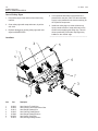
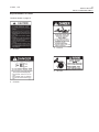
51-3845, 7/04
1
M26 SERIES
Mechanical Windrow Sweeper
For Simplicity Legacy
SWEEPSTER, Inc.
2800 N. Zeeb Road • Dexter, MI 48130
(734) 996-9116 • FAX (734) 996-9014
1-800-456-7100
2
51-3845, 7/04
51-3845, 7/04
3
Table of Contents
Section 1 ... Operation and Maintenance
Section 2 ... Service
Section 3 ... Parts
Section 4 ... Appendix
4
51-3845, 7/04
51-3845, 7/04
5
Operation and
Maintenance
M26 Series
Table of Contents
Introduction .............................................................. 7
Safety .................................................................... 6-12
General Safety Information ..................................... 8-9
Safety Signs and Labels .................................... 10-12
Operation ............................................................ 13-20
Installation ......................................................... 13-15
Operating Tips ................................................... 16-19
Removing Sweeper and Hitch ................................. 20
Maintenance ....................................................... 21-25
Daily Maintenance ............................................. 21-22
Brush Replacement ........................................... 22-24
Adjusting Drive Chain Idler ...................................... 25
Adjusting Brush Pattern ........................................... 25
6
SAFETY SECTION
Introduction
51-3845, 7/04
INTRODUCTION
Serial & Part Numbers
On your unit you will find a serial number plate and/or part number plate(s). The numbers on these plates are very
important if you wish to order parts or accessories. For your convenience, record numbers in the appropriate space
below.
51-3845, 7/04
7
Introduction
Importance of this Manual
This operator’s manual should be regarded as part of
the sweeper. Suppliers of both new and secondhand
sweepers are advised to keep documentation indicating that this manual was provided with the sweeper.
The manual contains information regarding installation,
operation and maintenance required for this sweeper
model and optional equipment. It also includes
detailed parts lists.
__________________________________________
Purpose of Sweeper
This sweeper is designed solely for use in construction
cleanup, road maintenance, grounds maintenance,
snow removal and similar operations. Use in any other
way is considered contrary to the intended use.
Compliance with and strict adherence to operation,
service and repair conditions, as specified by the
manufacturer, are also essential elements of the
intended use.
This sweeper should be operated, serviced and
repaired only by persons who are familiar with its
characteristics and acquainted with relevant safety
procedures.
Accident prevention regulations, all other generally
recognized safety regulations and all road traffic
regulations must be observed at all times.
SAFETY SECTION
INTRODUCTION
SWEEPSTER, Inc.
2800 North Zeeb Road
Dexter, Michigan 48130
Phone: (734) 996-9116 • (800) 456-7100
FAX: (734) 996-9014
e-mail: [email protected]
For help with installation, operation or maintenance
procedures, contact our Technical Service Department.
Direct product questions and parts orders to our Sales
Department.
When ordering parts or accessories, be prepared to
give the following information:
• Sweeper model, serial number and date of
purchase
• Prime mover make and model
• Part number, description and quantity
__________________________________________
Terms Used in Manual
Right-hand, left-hand, front and rear are determined
from the operator’s perspective (either the operator’s
seat or standing behind a walk-behind unit), facing
forward in the normal operating position.
Prime mover refers to the tractor, truck, loader or tow
vehicle that a sweeper is mounted on or towed by.
__________________________________________
Optional Equipment
Any modifications made to this sweeper may relieve
the manufacturer of liability for any resulting damage
or injury.
__________________________________________
Installation instructions for optional equipment, if
applicable, appear with parts lists in the back of the
manual.
__________________________________________
Safety Alert Symbol
Specifications & Features
This safety alert symbol indicates important
safety messages in this manual. When you see
this symbol, be alert to the possibility of injury.
Carefully read the message that follows and inform
other operators.
__________________________________________
Contacting SWEEPSTER
If you have any questions about information in this
manual or need to order parts, please call, write, FAX
or e-mail SWEEPSTER.
Due to continuous product improvement, specifications and features may change without notice.
__________________________________________
Warranty
To validate the warranty for this unit, fill out the warranty card or warranty pages located at the back of
this manual. Then, send this information to
SWEEPSTER.
__________________________________________
8
SAFETY SECTION
GENERAL INFORMATION
Safety Information
51-3845, 7/04
Read this Manual
• Check prime mover tire pressure before
sweeping.
Read all safety information in this manual. All operators
must read and understand the entire contents of this
manual before sweeping. General safety practices are
listed on Safety Information pages and specific safety
information is located throughout this manual.
__________________________________________
• Check tire ratings to be sure they match the
prime mover load. Weigh the sweeper end of the
prime mover, if necessary, to insure proper tire
rating.
Hazard Definitions
• Remove from the sweeping area all property that
could be damaged by debris flying from the
sweeper.
Four hazard classifications are used in this manual.
They are
CAUTION – Indicates a potentially hazardous
situation which, if not avoided, may
result in minor or moderate injury.
WARNING – Indicates a potentially hazardous
situation which, if not avoided,
could result in death or serious
injury.
DANGER – Indicates an imminently hazardous
situation which, if not avoided, will
result in death or serious injury.
IMPORTANT – Used for instructions when machine
damage may be involved.
__________________________________________
Operation
CAUTION – A sweeper is a demanding machine.
Only fully trained operators or trainee
operators under the close supervision
of a fully trained person should use
this machine.
Before sweeping:
• Learn sweeper and prime mover controls in an
off-road location.
• Be sure all persons not operating the sweeper
are clear of the sweeper discharge area.
• Always wear proper apparel such as a longsleeve shirt buttoned at the cuffs; safety glasses,
goggles or a face shield; ear protection; and a
dust mask.
When sweeping, adhere to all government rules, local
laws and other professional guidelines for your
sweeping application.
WARNING – Never raise the sweeper more than a
few feet off the ground. The sweeper
can tip back or the prime mover can
tip over causing death or serious
injury.
Before leaving the operator’s area for any reason –
lower the sweeper to the ground, stop the prime
mover engine, set the brakes and remove the key from
the ignition.
Minimize flying debris – use the slowest brush speed
that will do the job.
Keep hands, feet, hair and loose clothing away from
all moving parts.
• Be sure that you are in a safe area, away from
traffic or other hazards.
Leave the brush hood (shield) and all other shields and
safety equipment in place when operating the sweeper
and prime mover.
• Check all hardware holding the sweeper to the
prime mover, making sure it is tight.
Be aware of the extra weight and width a sweeper
adds. Reduce travel speed accordingly.
• Make sure all hydraulic fittings and hardware are
tight.
When sweeping on rough terrain, reduce speed to
avoid “bouncing” the sweeper. Loss of steering can
result.
• Replace any damaged or fatigued hardware with
properly rated fasteners.
Never sweep toward people, buildings, vehicles or
other objects that can be damaged by flying debris.
51-3845, 7/04
__________________________________________
Service & Repair
CAUTION – Do not modify the sweeper in any
way. Personal injury could result. If
you have questions, contact your
dealer or SWEEPSTER.
Repair or adjust the sweeper in a safe area, away from
road traffic and other hazards.
Before adjusting or servicing the sweeper – lower the
sweeper to the ground, stop the prime mover engine,
set the brakes and remove the key from the ignition.
When working on or around the sweeper, lower it to
the ground or secure it with transport chains or
cylinder-stop locks.
Stop the prime mover engine and cycle control levers
to release hydraulic pressure before servicing or
adjusting sweeper hydraulic systems.
WARNING – Escaping hydraulic fluid can have
enough pressure to penetrate the
skin, causing serious personal injury.
__________________________________________
9
SAFETY SECTION
GENERAL INFORMATION
51-3845, 7/04
10
SAFETY SECTION
SAFETY SIGNS AND LABELS
Care of Safety Signs
1. Keep safety signs clean and free from obstructing
material.
2. Clean safety signs with soap and water; dry with a
soft cloth.
3. Replace damaged or missing safety signs with new
signs from SWEEPSTER.
Locations
Item
1.
2.
3.
4.
5.
6.
7.
Part
50-0103
50-0104
50-0115
50-0145
50-0394
50-0076-1
50-0213
Description
Label, Caution, To Avoid Injury
Label, Danger, Lock-Collar, Unlock-Collar
Label, Danger, Rotating Drive
Label, Warning, Rotating Broom
Label, Danger, Rotating Drive Line
Label, Caution, Pinch Point
Label, Warning, Rotating Driveline
4. If a component with safety sign(s) affixed is replaced with a new part, make sure the new safety
sign(s) is (are) attached in the same location(s) as
the replaced components.
5. Install new safety signs on clean surfaces only.
Spray a weak solution of soap and water on the
surface before applying the safety sign. This will
allow repositioning of the label. Squeegee any
bubbles to the outside edge.
__________________________________________
51-3845, 7/04
Safety Signs & Labels
Representations of Labels
Locations shown on page 10.
1. 50-0103
3. 50-0115
4. 50-0145
2. 50-0104
11
SAFETY SECTION
SAFETY SIGNS AND LABELS
12
SAFETY SECTION
SAFETY SIGNS AND LABELS
51-3845, 7/04
Safety Signs & Labels
Representations of Labels (Continued)
Locations shown on page 10.
CAUTION
PINCH POINT
!
AVOID INJURY FROM
FRAME PIVOT AND STOPS.
Keep hands and feet away.
50-0076-1
6. 50-0076-1
7. 50-0213
5. 50-0394
51-3845, 7/04
13
Installation
OPERATION SECTION
INSTALLATION
Initial Installation
Follow the instructions for the subframe kit.
Install Front Hitch
1. Lift the hitch assembly (C, figure 1) slide onto the
slots on tractor (E). Lift back of hitch assembly to
frame (D) and install clevis pins (B), clevis pins (F)
and hair pins (A).
D
A
E
C
B
Many approved attachments have color coded
quick couplers to aid in installation. Match the
tractor quick coupler with the like colored
attachment quick coupler.
F
2. Install hydraulic cylinder hoses and fittings.
( figure 2)
Figure 1. Hitch to Tractor Installation
A. Hair Pin
D. Subframe
B. Clevis Pin, 5/8 x 1 13/16 E. Slots on Tractor
C. Assembly
F. Clevis Pin, 5/8 x 2 1/2
D
C
B
H
G
E
J
F
K
A
I
L
Figure 2. Cylinder/Hose Installation
A. Fitting, 1/8NPT x 1/2-20
B. Hose 30” Long
C. Fitting, Elbow, Swivel
D. Quick Disconnet
E. Hose 22” Long
F. Fitting, 1/8NPT x 7/16-20
G. Washer, Green
H. Washer, Yellow
I. Hydraulic Cylinder
J. Pin
K. Hair Pin
L. Hitch
14
51-3845, 7/04
Installation
OPERATION SECTION
INSTALLATION
F
A
E
C
B
D
E
Figure 1
A. Drive Shaft
B. Support Bracket
C. Front Hitch
D. Capscrews, 3/8-16 x 3/4
E. Carriage Bolts and Nuts
F. Set Collars
Install Long Drive Shaft
1. Slide the drive shaft (A, Figure 1) in from the front.
Line up the support bracket (B) with the front hitch
(C). Simultaneously line up the locking collar of the
drive shaft (A, Figure 12) with the gear drive of the
transmission (B).
2. Slide the support bracket (B, Figure 1) in to the
front hitch (C) about 1/2”. Connect the locking
collar (A, Figure 2). Pull back on the locking collar
(A) and slide the drive shaft fully onto the
transmission (B). Release the locking collar and
pull back on the drive shaft until the locking collar
locks onto the shaft.
A
4. Slide the support bracket (B, Figure 1) all the way
into the front hitch (C). The support bracket (B)
should be touching the front hitch. Tighten
capscrews (D).
Note: If the support bracket does not touch the front hitch
(C, Figure 1) loosen the set collars (F) carriage bolts
and nuts (E) holding the bearing holders. Slide the
bracket to the front hitch (C) and tighten the set
collars (F) carriage bolts and nuts (E). Secure the
bracket with the capscrews.
Figure 2
A. Drive Shaft Locking Collar
B. Transmission Shaft
B
51-3845, 7/04
15
OPERATION SECTION
INSTALLATION
Install Brush Head
1. Use tractor lift lever to lower hitch.
2. Position tractor in line with brush head.
3. Drive forward until hitch touches brush head, lift
hitch to engage implement.
4. Stop tractor engine, get off tractor, ensure pins
snap and engage into hitch. (figure 1.)
5. Connect drive line.
6. Connect cylinder to hitch and hydraulic lines to
tractor.
7. Place storage stands in up position.
Brush head not shown
Closed
(In)
Figure 1.
16
OPERATION SECTION
OPERATING TIPS
Before Operation
Operational Check
CAUTION – Contact with the sweeper, moving
joints or material discharged by the
brush can cause serious injury.
Operate this implement from the
operator’s seat only. Make sure
bystanders are well clear of the
sweeper and sweeper discharge area
before angling or engaging the
sweeper.
1. Lubricate all U-joints and driveline components on
the sweeper with high-quality, multi-purpose
grease.
51-3845, 7/04
5. Carefully examine the sweeper clearance under
the tractor undercarriage.
6. If sweeper shields or other parts contact the
undercarriage of the tractor in any way, remove the
sweeper from the tractor and follow the tractor
operator’s manual to adjust the implement lift
height adjustment linkages, limiting the maximum
lift height.
7. Reinstall the sweeper.
8. Start the tractor according to instructions in the
tractor operator’s manual.
2. Start the tractor according to instructions in the
tractor operator’s manual.
9. Engage the tractor PTO with the engine at 1,000
rpm. Note any excessive noise, vibration or other
problems.
3. Slowly raise the sweeper to the fully lifted position
with the implement lift.
10. Disengage the PTO, shut off the engine and
remove the key.
4. Stop the tractor and remove the key.
11. Correct any driveline problems before the unit is
put into service.
__________________________________________
CAUTION – Do not get under the sweeper at
any time while sweeper is in the
raised position.
51-3845, 7/04
Operating Instructions 4 WD hydraulic right
17
OPERATION SECTION
OPERATING TIPS
Operating Sweeper
Use the tractor lift lever to raise and lower the sweeper.
CAUTION – Operate this implement from the
operator’s seat only. Do not allow
other riders on the machine at any
time.
CAUTION – Operate this implement at a speed
that matches working conditions.
Be extremely careful when working
on banks or uneven terrain.
4 WD hydraulic left
4 WD hydraulic right
4 WD hydraulic lift
4 WD hydraulic lower
CAUTION – Operators must wear eye protection
(goggles, etc.) during operation.
For the most efficient operation, sweep with the tips of
the bristles like a broom – not with the sides of the
bristles like a mop. Adjust the brush contact according to instructions in Adjust Brush Contact Area (page
25).
For heavy material, reducing ground speed and
angling the brush fully right or left to gives the best
sweeping results. This allows the sweeper to discharge
material out of brush path area and prevents the “resweeping” of material.
For specific tips, see Snow Removal, Lawn Thatching,
Leaf Raking and General Sweeping• in this manual
section.
Brush stands must be placed in the raised position
before sweeping.
__________________________________________
Sweeper Control
WARNING – Contact with the tractor, sweeper or
debris discharged by sweeper can
cause serious injury. Be sure bystanders are completely clear of the
tractor, sweeper and sweeper
discharge area before operation.
CAUTION – Always wear eye protection when
operating any sweeper.
Use the tractor PTO to start and stop the sweeper
brush.
1. Start the engine and put the throttle lever at 1/3
speed.
2. Engage the PTO.
3. To stop, disengage the PTO.
Control brush speed with the throttle. If the brush stalls
frequently, increase the engine speed slightly. Find the
right brush and travel speeds so you don’t have to
increase the brush speed suddenly to overcome a
stall. Under most conditions, too fast of brush speeds
result in debris coming over the hood onto the
operator.
__________________________________________
Snow Removal
CAUTION – Foreign objects in snow may be
thrown farther than the snow itself.
Use the slowest brush speed that
will perform the job and always
remain aware of the sweeper
discharge direction.
CAUTION – Snow or ice build-up on the sweeper
hood can cause a loss of tractor
steering control. Regularly remove
any snow or ice from the sweeper
hood to prevent the excess weight
from affecting steering.
Vary the brush speed and sweeper angle so the
sweeper throws material out of the sweeper path
whenever possible.
Faster brush speeds perform better on wet, heavy
snow or slush.
This sweeper works best on snow depths of 6 in. (152
mm) or less, but almost any amount of snow can be
moved if ground speed is reduced. If snow carries over
to the rear of the brush, reduce speed and make a
second pass to produce a clean surface.
__________________________________________
18
OPERATION SECTION
OPERATING TIPS
Operating Instructions
51-3845, 7/04
Lawn Thatching
Leaf Raking
NOTE – Your sweeper is provided with a
polypropylene brush. Brushes with 1/2 poly–
1/2 wire or full wire sections may damage
lawns by pulling out the live grass. Brushes
made with wire are not recommended for lawn
thatching.
Carry the sweeper with implement lift slightly raised to
limit contact with the grass.
Carry the sweeper with the implement lift slightly raised
to limit ground contact. Brush bristles should barely
touch the ground while sweeping under load.
Use slower brush speeds and slow-to-medium travel
speeds when raking leaves.
For best results, rake leaves on days when leaf moisture is high.
__________________________________________
General Sweeping
Slower brush speeds and slower ground speeds are
more suitable for lawn thatching. This gives the brush
time to pull out the dead grass and minimizes the
bouncing of the brush head, which can cause lawn
damage due to excessive ground contact.
Minimize dust by reducing brush speeds and by
sweeping on days with high moisture. Try to keep wind
at your side or back. (Refer to figure 1.)
For light material, angle the sweeper 30° left or right.
Minimize dust by sweeping when moisture is high (but
not wet).
__________________________________________
Preferred Wind Directions
When Sweeping
Figure 1
Prevent damage to the sweeper by removing large
foreign objects.
__________________________________________
51-3845, 7/04
Troubleshooting
If Material Piles in Front of Sweeper
• Decrease travel speed
• Increase the engine rpm
• Make more than 1 pass
• Raise the brush to decease the contact area
• Increase the sweeper angle
__________________________________________
If Brush Wears Unevenly
• Check for material wrapped around the brush
• Clean underneath the hood
__________________________________________
If Driveline Wears Quickly
• Decrease travel speeds
• Make more than 1 pass, especially in deep, heavy
materials
• Avoid ramming piles
• Lack of lubrication – lubricate more often
__________________________________________
19
OPERATION SECTION
OPERATING TIPS
20
OPERATION SECTION
REMOVING SWEEPER AND HITCH
51-3845, 7/04
Removal/Storage
Sweeper & Hitch Removal
NOTE – Whenever removed, install clevis pins, hitch
pins, clips and hardware into the sweeper and
hitch for storage.
1. Install stands in storage position and fully lower
the attachment lift.
2. Disconnect the drive shaft by pulling back on the
locking collar and then pulling the shaft off.
3. Disconnect hydraulic hoses. Disconnect hairpins
and remove clevis pins. Slide hitch assembly off
the slots on the tractor.
4. Detach the sweeper from the sweeper hitch by
moving the shot pins into open position.
5. Lower the hitch to the ground and back out.
Brush head not shown
Lock
Open
(Out)
51-3845, 7/04
21
Maintenance
MAINTENANCE SECTION
DAILY MAINTENANCE
CAUTION – Allow only trained personnel to
operate or service this implement.
Know and understand all precautions before assembly, service or
operation. Also read and understand
all safety precautions in the tractor
operator’s manual.
Lubrication
Gearbox
figure 1
Check gearbox lubricant every 25 hours.
1. When oil is cold, remove the top plug (figure 1).
Make sure oil is level with the plug hole.
2. If needed, add gear oil meeting SPI GL5 80w-90
classification. Do not exceed a 50/50 mix with
synthetic oil.
3. Reinstall the plug.
NOTE – You do not have to change gearbox oil.
Drive Shaft
After every 8 operating hours, lubricate 3 grease points
(figure 2) on the drive shaft with multi-purpose grease.
Do not over grease universal joints.
Bearings
All bearings on the sweeper are permanently lubricated
for long life and require no lubrication.
Drive Chain
Lubricate with oil when changing brush sections.
__________________________________________
Tractor Air Filter
Due to dusty conditions, check the tractor air filter
often. Further instructions appear in the tractor
operator’s manual. Be sure to follow the recommendations for “extreme conditions” as the air filter can be
affected by dust and other debris raised by the
sweeper.
__________________________________________
figure 2
22
MAINTENANCE SECTION
DAILY MAINTENANCE/BRUSH REPLACEMENT
51-3845, 7/04
Maintenance
Daily Maintenance Checks
Hardware – Check and tighten all hardware on the
sweeper, including factory-installed hardware.
Brush Contact – Check brush contact. (See Adjusting
Brush Contact Area, page 25.)
__________________________________________
Brush Replacement
Replace sections when worn to 14 in. (356 mm) in
diameter.
NOTE – Replacing brush sections can be
accomplished more easily with the sweeper
mounted on the tractor than with it on the
ground.
Figure 2
Drive End
1. Remove the chain guard (figure 1) from the righthand side of the brush head.
2. Disconnect the drive chain (figure 2) at the master
link. Remove the chain from the large sprocket.
3. Loosen 2 set screws on each lock collar located at
each end of the brush core (figures 3 and 4).
4. Remove the chain guide plate (figure 5).
Figure 3
Bearing End
Figure 4
Figure 1
Figure 5
51-3845, 7/04
23
Maintenance
MAINTENANCE SECTION
BRUSH REPLACEMENT
5. Remove the snap ring from the large sprocket
(figure 6).
6. Remove the lock hub by removing all set screws
and then inserting the screw indicated in figure 7.
7. Remove the sprocket, washer and key from the
brush core.
8. Loosen 2 M8 hex nuts that retain the bearing on
the bearing end of the core (figure 8).
Figure 6
9. Slide the core to the toward the bearing end to
allow additional space on the other side.
10. Remove 3 M8 carriage bolts, lock washers and hex
nuts that retain the drive end bearing and flanges
(figure 9).
11. Pull the brush core from the brush frame (figure 10).
12. Remove 3 screws to take the retainer plate off the
core.
13. Remove old sections.
Continued on next page
Figure 7
Figure 9
Figure 8
Figure 10
24
MAINTENANCE SECTION
51-3845, 7/04
Maintenance
BRUSH REPLACEMENT
14. Install new sections by doing the following.
a. Number the tubes on the core as 1, 2, and 3
(figure 1).
b. Slide the first section onto the core with the
drive pins (figure 2) on both sides of tube 1.
Make sure that the drive pins face up.
NOTE – When using 1/2 poly–1/2 wire sections, place
a poly section first and last on the core to
prevent damage to the hood, driveline and
frame.
figure 1
c. Place the second section on the core with the
drive pins on both sides of tube 2. Be sure the
drive pins face down.
d. Put the third section on with the drive pins
around tube 3. Be sure the drive pins face up.
e. Slide sections on until the core is full, making
sure to alternate the tubes used and the
direction of the drive pins.
15. Put the retainer halves on the brush head and
reinstall the screws.
16. Position the brush head in front of the brush hood.
17. Place the bearing end of the brush core in the
bearing side of the brush head.
18. Place the drive end in the brush frame. The bearing
and flanges go between the brush frame and brush
core.
19. Slide the core toward the bearing end.
20. Install 3 M8 carriage bolts, lock washers and hex
nuts in the drive end bearing and flanges.
21. Tighten all set screws on lock collars.
Figure 2
22. Install the key, washer, sprocket, hub and snap
ring.
23. Tighten the hub onto the sprocket.
24. Clean and lubricate the drive chain. Then, install it.
25. Reinstall the chain guide plate.
26. Reinstall the chain guard. Insert a 1/8 in. (3 mm) or
smaller diameter pin punch through the hole in the
chain guard and into the idler to align the components.
27. Adjust the idler according to Adjusting Drive Chain
Idler (page 25). Adjust the brush by following
directions in Adjusting Brush Contact Area (page
25).
__________________________________________
51-3845, 7/04
25
Maintenance
MAINTENANCE SECTION
ADJUSTING DRIVE CHAIN IDLER/BRUSH PATTERN
Adjusting Drive Chain Idler
1. Clean debris off the idler adjustment screw
(figure 1) located on the drive end of the brush
head.
2. Disconnect the quick release end of the sweeper
drive shaft.
3. Raise the sweeper several inches off the ground.
4. Loosen the jam nut.
Figure 1
5. While rotating the brush manually, turn the idler
screw by hand until it will not tighten any more.
IMPORTANT – Avoid damage to the sweeper drive
mechanism. Tighten the idler by hand
only. Using a wrench or other tool can
result in overtightening the idler which
can damage the drive chain and other
parts.
6. Tighten the lock nut.
__________________________________________
Figure 2
Adjusting Brush Contact Area
Replacing Shear Bolt
NOTE – Keep tires at the correct pressure.
Replace the shear bolt in the end of the drive shaft if it
breaks.
1. Drive to a dirty section on a hard surface.
2. Set the brush on the ground and run it 30 seconds
without moving the tractor.
1. Remove any remaining parts of the broken shear
bolt.
2. Install a new shear bolt.
3. Stop, raise the brush head assembly, back away
and park the tractor.
4. Measure the path cleared. If the sweeper is adjusted correctly, the path will be 2-3 in. (51-76 mm)
wide.
5. Adjust brush contact area with the brush adjustment knob (figure 2). To make the path wider, lower
the brush head assembly by turning the knob to
the left (counterclockwise). To create a narrower
path, raise the brush head assembly by turning the
knob to the right (clockwise).
__________________________________________
3. Check the condition of the snap ring retaining the
drive shaft. Replace if it is broken or damaged.
__________________________________________
Safety Labels
Replace worn or damaged safety labels before the
sweeper is operated. If any safety labels become
damaged when parts are repaired, replace those
labels before operating the sweeper.
Keep all safety labels clean so they are easy to read.
Order replacement safety labels (shown on pages 1112 of this manual). Replacement safety labels are
supplied at no charge.
See page 10 for the location of safety labels on the
sweeper.
__________________________________________
51-3845, 7/04
26
Notes
51-3845, 7/04
27
Parts
M26 Series
Table of Contents
Parts List ............................................................ 28-32
Brush Head ........................................................ 28-29
Hitch ....................................................................... 30
Mounting Hardware ................................................ 31
Sections .................................................................. 32
28
PARTS SECTION
BRUSHHEAD ASSEMBLY
Item
1.
2.
3.
4.
5.
6.
7.
8.
9.
10.
11.
12.
13.
14.
15.
16.
17.
18.
19.
20.
21.
22.
23.
24.
25.
26.
27.
28.
29.
30.
31.
32.
33.
34.
35.
Part
01-5847
51-3845, 7/04
Brush Head
Qty Description
24 Section, 26, 8 P, Convoluted, Black
(4 Ft Broom)
31 Section, 26, 8 P, Convoluted, Black
(5 Ft Broom)
06-0433 1 Sprocket, 50B11 x 1 Bore x 1/4 Key
06-0434 1 Sprocket, 50B36, Tapered Bore
06-0435 1 Hub, Taper, 1.00 Bore, 1/4 Key
06-0436 1 Chain, #50, 78 Pitches
07-0193 1 Pin, Clevis, Gr2, 3/8 x 1 1/8
07-0210 1 Clip, Hairpin, 14Ga x 1.75
07-1075 7 Rivet, Pop, Gr2, 3/16 x 3/4
07-1090 1 Pin, Clevis, Gr2, 1/2 x 5, Grip 4.75
07-1679 10 Plug, Cap, Plastic, for 5/16 Hole
07-1810 1 Nut, Lock, Center, Gr2, 5/16-18
07-2950 10 Bolt, Carriage, Cl8.8, M8 x 1.25 x 20
07-2952 32 Screw, Cl10.9, M6 x 1 x 20
07-2954 10 Nut, Hex, Gr5, M8 x 1.25
07-2956 30 Nut, Insert, M6 x 1 Grip .027-.165
07-3273 8 Washer, Lock, Split, Medium, 5/16
07-3922 2 Nut, Insert, M6 x 1, Grip .165-.251
07-3939 3 Ring, Snap, 1 x .078
07-4089 1 Screw, Tap, 5/16-18 x 2.25
07-4090 2 Washer, 1.5 x 1 x .075
07-4417 1 Chain, Guide
07-4473 1 Shield, Drive shaft
07-4484 1 Screw, Panhead, 8-18 x 1/2
07-4522 2 Clip, Hairpin, .162 x 3.43
07-4523 4 Plug, Cap, Plastic, Black, 1 x .51
07-4656 1 Tag, Plastic, Red, Remove Before Use
07-4987 1 Shield, Drive shaft, with Hole
(4 Ft Broom)
07-4472 1 Shield, Drive shaft, with Hole
(5 Ft Broom)
08-0005 2 Flange, Bearing, 2 Holes
08-0008 4 Bearing, Flange, 3 Hole
08-0148 3 Bearing, 1 RD, with Collar/Set Screw
11-5131 1 Assembly, Mounting, QA
13-10018 1 Weld, Frame, Brush (4 Ft Brush)
13-9593 1 Weld, Frame, Brush (5 Ft Brush)
13-1321 1 Key, 1/4 x 1/4 x 2
13-5723 1 Weld, Adjustment, Brush Head
13-5740 2 Plate, Retainer, Bushing, Swing
Item
36.
37.
38.
39.
40.
41.
42.
43.
44.
45.
46.
47.
48.
49.
50.
51.
52.
53.
54.
55.
56.
57.
58.
59.
60.
63.
64.
65.
66.
Part
Qty Description
13-5741 1
13-5742 1
13-8384 1
13-8390 2
13-8396 1
13-8420 1
13-8472 3
13-8557 2
13-9456 2
13-9457 1
13-9591 1
13-9652 1
13-8391 1
13-9655 1
13-8415 1
13-9659 1
13-5743 1
13-9698 2
13-9817 1
13-9818 2
50-0014-1 1
50-0076-1 2
50-0103 1
50-0104 1
50-0115 1
50-0213 2
50-0391 2
50-0718 1
07-3270 2
07-4033 3
07-4668 3
13-8385 2
Sheet, Hood, Side, Left
Sheet, Hood, Side, Right
Knob, Pattern, Adjustment, 5/8-8
Bushing, Brush Head, Swing
Plate, Retainer, Core
Weld, Idler
Assembly, Plate, Locking
Assembly, Support, Hood
Plate, Keeper
Plate, Spacer, Chain Guide
Weld, Cover, Brush Frame Side
Weld, Core (4 Ft Brush)
Weld, Core (5 Ft Brush)
Shaft, Drive Line (4 Ft Brush)
Shaft, Drive Line (5 Ft Brush)
Sheet, Hood (4 Ft Brush)
Sheet, Hood (5 Ft Brush)
Key, 1/4 x 1/4 x 15/16
Weld, Stand, Holder
Tube, Rd, Stand
Label, Caution, Read Manual
Label, Caution, Pinch Point
Label, Caution, Avoid Personal Injury
Label, Danger, Lock Collar
Label, Danger, Rotating Drive Line
Label, Warning, Rotation, Shaft
Label, Warning, Rotating Broom
Label, Serial Number
Nut, Hex, Nylock, Gr8, 5/16-18
Nut, Hex, Nylock, 1/4-20
Screw, HHC, Gr2, 1/4-20 x 2 1/2
Bolt, Shear
51-3845, 7/04
Brush Head
Brush Head
29
PARTS SECTION
BRUSHHEAD ASSEMBLY
30
51-3845, 7/04
Angling Rod
PARTS SECTION
HITCH ASSEMBLY
22
4
2
21
17
11
20
16
6
10
18
14
8
1
5
3
12
19
13
FINAL INSTALLATION VIEW
OF 11-1533
Item Part
1.
2.
3.
4.
5.
6.
7.
8.
9.
10.
11.
05-1409
05-1291
07-0018
07-0699
07-1718
07-2843
07-3013
07-3015
07-4367
07-3112
07-4033
Qty Description
1
1
8
2
8
2
2
8
2
2
1
Gearbox, Omni, 3:1
Shaft, Drive
Screw, HHC, Gr8, 3/8-16 x 1
Pin, Cotter, Gr2, 1/8 x 1 1/4
Washer, Lock, Split, Medium, 3/8
Pin, Klick, 3/16 x 1, 5/8
Bushing, Caster
Spacer, Caster
Wheel, Caster, 6.25 x 5/8
Fitting, Zerk, 1/4-28, Self Tap
Nut, Hex, Nylock, Gr8, 1/4-20
7
9
Item Part
12.
13.
14.
16.
17.
18.
19.
20.
21.
22.
Qty Description
07-3676
07-4037
08-0131
11-5133
13-13159
13-13164
13-4291
07-2914
13-9541
50-0394
2
2
4
1
1
1
2
1
2
2
Screw, HHC, Gr8, 1/2-13 x 5
Nut, Hex, Nylock, Gr8, 1/2-13
Bearing, Caster
Kit, Mounting, Hardware
Weld, Mounting, QA
Weld, Swing, Frame
Weld, Caster, Fork
Bolt, Shear, Gearbox
Pin, Clevis, .75 x 1.11
Label, Danger, Rotating Drive Line
Not Shown
11-5132
1 Kit, Hydraulic, Swing
51-3845, 7/04
31
PARTS SECTION
MOUNTING HARDWARE
Kit 11-5133 Mounting Hardware
#1709659 (QTY 2)
#1709660 (QTY 2)
#1960587 (QTY 2)
#1924366 (QTY 2)
11-5132 Kit Hydraulic Swing
Part #
1725359
1725049
1918452
1725322
1960033
919171
172320
1725318
1725319
173359
1725520
1726321
1726319
Qty
1
1
1
1
1
1
1
1
1
2
2
2
2
32
PARTS SECTION
SECTIONS
Item
1.
Part
Notes
Qty Description
01-0924 1 Section, Set, 26, 8, Combination, Convoluted
51-3845, 7/04
51-3845, 7/04
33
Appendix
M26 Series
Table of Contents
Hardware and Torque Specifications ......................... 34
Warranty .............................................................. 35-36
34
51-3845, 7/04
Torque Values
APPENDIX
HARDWARE/TORQUE SPECIFICATIONS
Hardware Identification & Torque Specifications
Common Hardware Types
Torque Specification Chart
Hex Head Capscrew
FOR STANDARD MACHINE HARDWARE (Tolerance ± 20%)
Washer
Hardware
Grade
Lockwasher
Carriage Bolt
No
Marks
SAE Grade 2
Hex Nut
Size Of
Hardware
Standard Hardware Sizing
8-32
8-36
10-24
10-32
1/4-20
1/4-28
5/16-18
5/16-24
3/8-16
3/8-24
7/16-14
7/16-20
1/2-13
1/2-20
9/16-12
9/16-18
5/8-11
5/8-18
3/4-10
3/4-16
7/8-9
7/8-14
1-8
1-12
When a washer or nut is identified as 1/2”, this is the
Nominal size, meaning the inside diameter is 1/2 inch; if a
second number is present it represent the threads per inch
When bolt or capscrew is identified as 1/2 - 16 x 2”, this
means the Nominal size, or body diameter is 1/2 inch; the
second number represents the threads per inch (16 in this
example, and the final number is the body length of the
bolt or screw (in this example 2 inches long).
The guides and ruler furnished below are designed to
help you select the appropriate hardware and tools.
0
1/4
Nut, 1/2”
1/2
Inside
Diameter
3/4
1
1/4
1/2
3/4
Screw, 1/2 x 2
2
1/4
Body
Diameter
in/lbs
ft/lbs
19
20
27
31
66
76
11
12
20
23
30
35
50
55
65
75
90
100
160
180
140
155
220
240
Nm.
2.1
2.3
3.1
3.5
7.6
8.6
15.0
16.3
27.2
31.3
40.8
47.6
68.0
74.8
88.4
102.0
122.4
136
217.6
244.8
190.4
210.8
299.2
326.4
SAE Grade 5
in/lbs
ft/lbs
30
31
43
49
8
10
17
19
30
35
50
55
75
90
110
120
150
180
260
300
400
440
580
640
SAE Grade 8
Nm.
in/lbs
ft/lbs
Nm.
3.4
3.5
4.9
5.5
10.9
13.6
23.1
25.8
40.8
47.6
68.0
74.8
102.0
122.4
149.6
163.2
204.0
244.8
353.6
408.0
544.0
598.4
788.8
870.4
41
43
60
68
12
14
25
27
45
50
70
80
110
120
150
170
220
240
386
420
600
660
900
1,000
4.6
4.9
6.8
7.7
16.3
19.0
34.0
34.0
61.2
68.0
95.2
108.8
149.6
163.2
204.0
231.2
299.2
326.4
525.0
571.2
816.0
897.6
1,244.0
1,360.0
NOTES
1. These torque values are to be used for all hardware
excluding: locknuts, self-tapping screws, thread forming
screws, sheet metal screws and socket head setscrews.
2. Recommended seating torque values for locknuts:
a. for prevailing torque locknuts - use 65% of grade 5
torques.
b. for flange whizlock nuts and screws - use 135% of
grade 5 torques.
3. Unless otherwise noted on assembly drawings, all torque
values must meet this specification.
1/2
Body
Length
3/4
3
1/4
1/2
3/4
4
Wrench & Fastener Size Guide
1/4
5/16
3/8
1/4” Bolt or Nut
Wrench—7/16”
5/16” Bolt or Nut
Wrench—1/2”
3/8” Bolt or Nut
Wrench—9/16”
7/16
DIA.
7/16” Bolt or Nut
Wrench (Bolt)—5/8”
Wrench (Nut)—11/16”
1/2
DIA.
1/2” Bolt or Nut
Wrench—3/4”
City
Date Delivered to Customer __________
Date Delivered to Dealer ___________
City
Zip
Phone
Form: SWR Rev 4/97
White-Customer Yellow-Dealer Card-Return to Sweepster postage paid
State
_______________________________________________________
Address
_______________________________________________________
Dealer's Name
_______________________________________________________
Engine Model _____________________
Engine Make ____________________
Phone
Serial Number _____________________
Zip
Model Number ___________________
State
_______________________________________________________
Address
_______________________________________________________
Purchaser's Name
_______________________________________________________
PLEASE PRINT - PRESS HARD MULTIPLE COPIES
Thank you for purchasing a Sweepster product. Warranty protection
on this equipment is valid only when completed and signed by customer
and dealer and mailed to SWEEPSTER. If you have any questions, please
give us a call at 1-800-456-7100 or (734) 996-9116.
_____________________________________________________
_____________________________________________________
7. SUGGESTIONS/COMMENTS? ___________________________
6. PLEASE RATE THE FOLLOWING (check one)
Appearance:
Excellent Good Poor
Delivery Time:
Excellent Good Poor
Sales Service:
Excellent Good Poor
Performance:
Excellent Good Poor
Technical Support:
Excellent Good Poor
5. WHY DID YOU PURCHASE A SWEEPSTER? (check one)
Quality
Price
Reputation
Simplicity
Prior Use
Dealer Referral
Operation
Features
Availability
Other _____________________________________________
4. DID THE UNIT FIT CORRECTLY TO PRIME MOVER?
Yes
No Comments ______________________________
3. DID YOU OR YOUR CUSTOMER RECEIVE AN
OPERATION/PARTS MANUAL?
Yes
No
2. MAKE AND MODEL NUMBER OF PRIME MOVER.
(For attachment sweepers only.) __________________________
1. MATERIAL YOU ARE SWEEPING?
Snow
Dirt
General Debris
Thatch
Other ____________________________________________
SWEEPSTER WARRANTY REGISTRATION
51-3845, 7/04
APPENDIX
WARRANTY INFORMATION
35
36
Warranty Information
one year
12
APPENDIX
WARRANTY INFORMATION
51-3845, 7/04