1
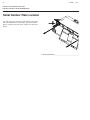
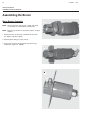
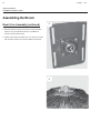
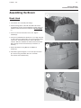
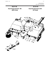
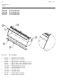
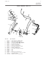
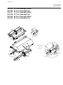
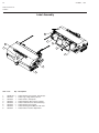
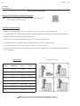
51-3606-1, 7/05
1
BIG
DAWG
Series
Pickup Sweeper
for Skid Steer Loaders
Sweepster Serial Number__________________
800-456-7100
www.paladinbrands.com
Manual Number: 51-3606
Release Date: February 2005
Sweepster 2800 N. Zeeb Rd., Dexter, MI. 48130, United States of America
2
51-3606-1, 7/05
51-3606-1, 7/05
3
Table of Contents
Section 1 ... Operation and Maintenance
Section 2 ... Service Manual
Section 3 ... Parts Manual
Section 4 ... Appendix
4
51-3606-1, 7/05
51-3606-1, 7/05
Operation and
Maintenance Manual
Pick-Up Sweeper
Big Dawg Series
5
6
51-3606-1, 7/05
51-3606-1, 7/05
7
TABLE OF CONTENTS
OPERATION AND MAINTENEANCE
Table of Contents
Introduction ............................................................... 8
.
Safety .....................................................9-13
Safety Information ............................................... 9-10
Safety Signs and Labels .................................... 11-12
Mounting and Dismounting ..................................... 13
Operation .............................................14-16
Operating Tips ........................................................ 14
Sweeper Installation ............................................... 15
Sweeper Removal ................................................... 16
Storage ................................................................... 16
Product Specifications .......................17-18
Specifications and Model Views ............................. 17
Product I.D. Information .......................................... 18
Maintenance ........................................19-24
Lubrication Points ................................................... 19
Brush Pattern Adjustment ....................................... 20
Brush Section Replacement ................................... 21
Chain Attachment ................................................... 22
Chain Adjustment ................................................... 22
Maintenance Schedule ........................................... 23
Hydraulic Inspection Guideline ................................ 23
Maintenance Log .................................................... 24
8
51-3606-1, 7/05
SAFETY SECTION
INTRODUCTION
Introduction
Contacting SWEEPSTER
Importance of this Manual
If you have any questions about information in this manual or
need to order parts, please call, write, fax or e-mail
SWEEPSTER.
Read this manual before attempting to operate
the equipment.
This operator’s manual should be regarded as part of the
sweeper. Suppliers of both new and secondhand sweepers
are advised to keep documentation indicating that this
manual was provided with the sweeper.
The manual contains information regarding installation,
operation and maintenance required for this sweeper and
optional equipment. It also includes detailed parts lists.
SWEEPSTER, LLC.
2800 North Zeeb Road
Dexter, Michigan 48130
Phone: (734) 996-9116 - (800) 456-7100
FAX: (734) 996-9014
e-mail: [email protected]
For help with installation, operation or maintenance
procedures, contact our Technical Service Department. Direct
product questions and parts orders to our Sales Department.
Purpose of Sweeper
This sweeper is designed solely for use in construction
cleanup, road maintenance, grounds maintenance and
similar operations. Use in any other way is considered
contrary to the intended use. Compliance with and strict
adherence to operation, service and repair conditions, as
specified by the manufacturer, are also essential elements of
the intended use.
This sweeper should be operated, serviced and repaired only
by persons who are familiar with its characteristics and
acquainted with relevant safety procedures.
When ordering parts or accessories, be prepared to give the
following information:
•Sweeper model, serial number and date of
purchase
•Prime mover, make and model
•Part number, description and quantity
Terms Used in Manual
Accident prevention regulations, all other generally
recognized safety regulations and all road traffic regulations
must be observed at all times.
Right-hand, left-hand, front and rear are determined from the
operator’s perspective (either the operator’s seat or standing
behind a walk-behind unit), facing forward in the normal
operating position.
Any modifications made to this sweeper may relieve the
manufacturer of liability for any resulting damage or injury.
Prime mover refers to the tractor, truck, loader or tow vehicle
that the sweeper is mounted on or towed by.
Safety Alert Symbol
Optional Equipment
This safety alert symbol indicates important safety
messages in this manual. When you see this symbol,
be alert to the possibility of injury. Carefully read the message
that follows and inform other operators.
Installation instructions for optional equipment, if applicable,
appear in the Service Manual Section.
Specifications & Features
Due to continuous product improvement, specifications and
features may change without notice.
Warranty
To validate the warranty for this unit, fill out the warranty card
or warranty pages located at the back of this manual. Then,
send this information to SWEEPSTER.
51-3606-1, 7/05
9
SAFETY SECTION
GENERAL SAFETY INFORMATION
Safety Information
Read this manual
Read all safety information in this manual. All
operators must read and understand the entire
contents of this manual before sweeping.
General safety practices are listed on Safety
Information pages and specific safety
information is located throughout this manual.
Hazard Definitions
Four hazard classifications are used in this manual. They are
•Check prime mover tire pressure before sweeping.
•Check tire ratings to be sure they match the prime
mover load. Weigh the sweeper end of the prime
mover, if necessary, to insure proper tire rating.
•Remove from the sweeping area all property that
could be damaged by debris flying from the
sweeper.
•Be sure all persons not operating the sweeper are
clear of the sweeper discharge area.
•Always wear proper apparel such as a long-sleeved
shirt buttoned at the cuffs; safety glasses, goggles
or a face shield; ear protection; and a dust mask.
While sweeping:
CAUTION - Indicates a potentially hazardous
situation which, if not avoided, may result
in minor or moderate injury.
WARNING -Indicates a potentially hazardous
situation which, if not avoided, could
result in death or serious injury.
DANGER - Indicates an imminently hazardous
situation which, if not avoided, will result
in death or serious injury.
IMPORTANT - Used for instructions when machine damage
may be involved.
Operation
CAUTION - A sweeper is a demanding machine.
Only fully trained operators or trainee
operators under the close supervision of
a fully trained person should use this
machine.
Before sweeping:
•Learn sweeper and prime mover controls in an off-road
location.
•Be sure that you are in a safe area, away from traffic or
other hazards.
•Check all hardware holding the sweeper to the host
machine, making sure it is tight.
•Replace any damaged or fatigued hardware with
properly rated fasteners.
•Make sure all hydraulic hardware and hydraulic fittings
are tight.
•Replace any damaged or fatigued fittings or hoses.
•When sweeping, adhere to all government rules, local
laws and other professional guidelines for your
sweeping application.
•Before leaving the operators area for any reason, lower
the sweeper to the ground. Stop the prime mover
engine, set the brakes and remove the key from the
ignition.
•Minimize flying debris - use the slowest brush speed that
will do the job. See Operation Section: Operating Tips.
•Keep hands, feet, hair and loose clothing away from all
moving parts.
•Leave the brush hood (shield) and all other shields and
safety equipment in place when operating the sweeper
and prime mover.
•Be aware of the extra weight and width a sweeper adds.
Reduce travel speed accordingly. See Product
Information Section.
•When sweeping on rough terrain, reduce speed to avoid
“bouncing” the sweeper. Loss of steering can result.
•Never sweep toward people, buildings, vehicles or other
objects that can be damaged by flying debris.
•Only operate the sweeper while you are in the seat of
the prime mover. The seat belt must be fastened while
you operate the prime mover. Only operate the controls
while the engine is running. Protective glasses must be
worn while you operate the prime mover and while you
operate the sweeper.
•While you operate the sweeper slowly in an open area,
check for proper operation of all controls and all
protective devices. Note any needed repairs during
operation of the sweeper. Report any needed repairs.
10
51-3606-1, 7/05
SAFETY SECTION
GENERAL SAFETY INFORMATION
Service & Repair - General
CAUTION - Do not modify the sweeper in any way.
Personal injury could result. If you have
questions, contact your dealer or
SWEEPSTER.
Repair or adjust the sweeper in a safe area, away from road
traffic and other hazards.
Before adjusting or servicing the sweeper - lower the
sweeper to the ground, stop the prime mover engine, set the
brakes and remove the key from the ignition.
When working on or around the sweeper, lower it to the
ground or secure it with transport chains or cylinder-stop
locks.
Service & Repair - Hydraulic Safety
Stop the prime mover engine and cycle control levers to
release hydraulic pressure before servicing or adjusting
sweeper hydraulic systems.
WARNING - Escaping hydraulic fluid can have
enough pressure to penetrate the skin,
causing serious personal injury.
Check lines, tubes and hoses carefully. Do not use your bare
hand to check for leaks. Use a board or cardboard to check
for leaks. Tighten all connections to the recommended torque.
Do not bend high pressure lines. Do not strike high pressure
lines, Do not install bent lines, bent tubes, or kinked hoses. Do
not install damaged lines, damaged tubes, or damaged
hoses.
Repair loose lines, loose tubes, and loose hoses. Repair
damaged lines, damaged tubes, and damaged hoses. Leaks
can cause fires. See your SWEEPSTER dealer for repair or
replacement parts.
Replace the parts if any of the following conditions are
present:
•The end fittings are damaged or leaking.
•The outer covering is chafed or cut.
•The reinforcing wire layer is exposed.
•The outer covering is ballooning locally.
•The hose is kinked or crushed.
•The armoring embedded in the outer cover.
•The hoses have been pulled or stretched.
Make sure that all clamps, guards, and shields are installed
correctly.
51-3606-1, 7/05
11
SAFETY SECTION
SAFETY SIGNS & LABELS
Safety Signs and Labels
There are several specific safety signs on this sweeper. The
exact location of the hazards and the description of the
hazards are reviewed in this section.
Make sure that all the safety signs are legible. Clean the
safety signs or replace the safety signs if you cannot read the
words. Replace the illustrations if the illustrations are not
legible. When you clean the safety signs, use a cloth, water
and soap. Do not use solvent, gasoline, or other harsh
chemicals to clean the safety signs. Solvents, gasoline, or
other harsh chemicals will loosen the adhesive that secures
the safety sign. Loose adhesive will cause the safety sign to
fall. Replace any safety sign that is damaged or missing. If a
safety sign is attached to a part that is replaced, install a
safety sign on the replacement part. Contact your
SWEEPSTER dealer for replacement safety signs.
This warning label is located on the back of the brush hood
near the center.
WARNING - Do not operate or work on this machine
or sweeper unless you have read and
understand the instructions and
warnings in the Operation and
Maintenance Manuals and Owner’s
Manuals. Failure to follow the
instructions or heed the warnings could
result in injury or death. Contact your
SWEEPSTER dealer for replacement
manuals. Proper care is your
responsibility.
12
51-3606-1, 7/05
SAFETY SECTION
SAFETY SIGNS AND LABELS
Safety Signs and Labels
WARNING - Keep clear. Pivoting bucket can cause
severe bodily harm.
This warning label is located on the right and left hand side at
the rear of the brush hood.
WARNING - Keep clear. Pivoting bucket can cause
severe bodily harm.
This warning label is located on both sides of the brush head
near the bucket.
IMPORTANT - Only use indicated tie down points. Failure
to do so may result in damage to machine
51-3606-1, 7/05
13
OPERATING SECTION
MOUNTING & OPERATING TIPS
Mounting and Dismounting
•Get on the prime mover only at locations that are equipped
with steps and/or handholds. Get off the prime mover only at
the locations that are equipped with steps and/or
handholds. Utilize the steps that are provided on the
sweeper when you get on the prime mover and when you
get off the prime mover.
•Before you get on the prime mover, clean the steps and
handholds. Inspect the steps and the handholds. Make all
necessary repairs.
•Face the prime mover whenever you get on the prime mover
and whenever you get off the prime mover.
•Maintain a three-point contact with the steps and the hand
holds.
NOTE - Three-point contact can be two feet and one hand.
Three-point contact can also be one foot and two
hands.
•Do not get on a moving prime mover or on an operating
sweeper. Do not get off a moving prime mover.
•Never jump off the prime mover or off the sweeper.
•Do not use any controls as handholds when you enter the
operator’s compartment or when you exit the operator’s
compartment.
Operating Tips
Before each Use
Perform daily maintenance as indicated in the Maintenance
Schedule.
Run the prime mover and sweeper at a slow idle. Check for
hydraulic leaks or other problems and make corrections, if
necessary, before using the sweeper. See hydraulic
inspection guideline.
During Use
WARNING - Avoid serious injury. Check for objects
that could harm the operator or others if
thrown by the sweeper. Remove these
items before sweeping.
Carry the sweeper low to the ground so that the operator has
good visibility. Avoid any sudden movements from one side
to the other side when you carry a sweeper.
Avoid excessive downward pressure on the broom in order to
prevent excessive wear. A two to six inch wide pattern is
sufficient for most applications. Ensure that the motor and
bearing plates are equally adjusted in order to prevent an
uneven wear pattern. To adjust brush pattern see
Maintenance Section.
Directing Debris
Observe wind direction. Sweeping with the wind makes
sweeping more effective and helps keep debris off the
operator.
If necessary, use the dust suppression kit to suppress the
dust.
14
OPERATION SECTION
OPERATING TIPS
Operating Tips
Important - Avoid sweeper damage. Do not ram into piles.
Use a dozer blade for this type of job.
Brush, Engine & Travel Speeds
Vary brush, engine and travel speeds to match sweeping
conditions.
Dirt & Gravel
To keep dust at a minimum, plan sweeping for days when it is
overcast and humid or after it has rained. Also, sweep so the
wind blows at your back.
Low brush speeds and moderate travel speeds work best for
cleaning debris from hard surfaces. Brush speeds that are
too fast tend to raise dust because of the aggressive sweeper
action.
Heavy Debris
Travel slowly - less than 5 mph (8 kph)
Sweep a path less than the full width of the sweeper.
Increase engine speed if debris becomes very heavy.
51-3606-1, 7/05
51-3606-1, 7/05
15
OPERATION SECTION
SWEEPER INSTALLATION
Sweeper Installation
13. Move the coupler pins to the engaged position.
WARNING - Improper attachment of sweeper could
result in injury or death. Do not operate
this machine until you have positive
indication that the coupler pins are fully
engaged.
To check for engagement:
1. Keep the sweeper close to the ground.
2. While the lift arms are fully lowered, visually inspect the
quick coupler to ensure that the coupler pins are fully
extended through the corresponding holes of the sweeper
mounting bracket.
Installation
1. Position the pick up broom on a level surface.
2. Ensure that the coupler pins are in the disengaged
position.
3. Enter the machine.
4. Fasten the seat belt.
5. Start the engine.
6. Disengage the parking break.
7. Tilt the quick coupler assembly forward.
8. Align the quick coupler assembly between the outer plates
of the mounting bracket. Move the quick coupler assembly
under the angled plate of the mounting bracket. Rack back
on the broom.
9. Engage the parking brake.
10. Stop the engine.
11. Cycle controls to relieve any pressure within the auxiliary
hydraulic lines.
12. Exit the machine.
14. Ensure that the quick disconnect couplings are clean.
Connect auxiliary hydraulic lines for the broom to the
prime mover. Twist the collar of the quick disconnect for
one quarter of a turn in order to secure the hydraulic
connections.
15. Attach shackle end of chains to SSL grab bars. See Chain
Adjustment section for proper adjustment.
16. While the loader arms are lowered, visually inspect the
quick coupler in order to ensure that the coupler pins are
fully extended through the corresponding holes of the
sweeper mounting bracket.
WARNING - Improper attachment of sweeper could
result in injury or death. Do not operate this
machine until you have positive indication
that the coupler pins are fully engaged.
16
51-3606-1, 7/05
OPERATION SECTION
SWEEPER REMOVAL & STORAGE
Sweeper Removal
WARNING - Disengaging the coupler pins will release
the sweeper from control of the operator.
Serious injury or death may result from
disengaging the sweeper when the
sweeper is in an unstable position or
carrying a load. Place the sweeper in a
stable position before disengaging the
coupler pins.
IMPORTANT - Auxiliary hoses for the sweepers must be
removed before the quick coupler is
disengaged. Pulling the sweeper with the
auxiliary hoses could result in damage to the
prime mover or the sweeper.
1. Lower the pick up broom to the ground.
2. Place the direction control in NEUTRAL. Engage the
parking brake.
3. Stop the engine.
4. Cycle controls to relieve any pressure within the auxiliary
hydraulic lines.
5. Exit the machine.
6. Remove chains from the SSL grab bars.
7. Disconnect the auxiliary hydraulic lines from the prime
mover.
8. Move the coupler pins to the DISENGAGED position.
9. Enter the machine.
10.Fasten the seatbelt.
11.Start the engine.
12.Disengage the parking brake.
13.As you slowly back away from the mounting bracket, tilt
quick coupler assembly forward until the top of quick
coupler assembly clears the angled plate.
14.Back away from the pick-up broom.
Storage
Never rest the broom on the bristles. Resting the broom on
the bristles could cause the bristles to become deformed and
unbalanced. Use stands in order to support the broom when
the broom is not operating.
IMPORTANT - Do not store the sweeper with weight on the
brush. Weight will deform the bristles, destroy
ing the sweeping effectiveness. To avoid this
problem, place the sweeper on blocks or use
stands.
Do not store polypropylene brushes in direct
sunlight. The material can deteriorate and
crumble before the bristles are worn out.
Keep polypropylene brush material away from
intense heat or flame.
51-3606-1, 7/05
17
PRODUCT INFORMATION SECTION
SPECIFICATIONS & MODEL VIEWS
Product Information
Section
BDC Pick-Up Broom
Maximum Weight with
Bucket
Specifications and Model
Views
1220 lbs (BDC62)
1370 lbs (BDC74)
1525 lbs (BDC84)
Actual Sweeping Width
62 inches (BDC62)
74 inches (BDC74)
84 inches (BDC84)
Maximum length
65 inches (all models)
Maximum Width
75 inches (BDC62)
87 inches (BDC74)
97 inches (BDC84)
Maximum Hydraulic
Oil Flow
25 gpm
Maximum Hydraulic
Oil Pressure
3000 psi
Width
Length
18
51-3606-1, 7/05
PRODUCT INFORMATION SECTION
PRODUCT IDENTIFICATION INFORMATION
Serial Number Plate Location
For quick reference, record the serial number in the space
that is provided below the illustration. The serial number
plate is located on the back of the sweeper just above the
bucket.
Pick-Up Serial Number__________________________________
51-3606-1, 7/05
19
MAINTENANCE SECTION
LUBRICATION POINTS
Lubrication Points
The following grease fittings should be greased before each
use. See figure for locations.
1. Core bearing ( 1 fitting )
2. Caster ( 2 fittings )
3. Bucket Pivot ( 1 fitting each )
1
3
2
20
51-3606-1, 7/05
MAINTENANCE SECTION
BRUSH PATTERN ADJUSTMENT
Brush Pattern
1
A properly adjusted brush offers the best sweeper
performance. To check the brush pattern:
1. Move the sweeper to a dusty, flat surface.
2. Set the prime movers parking brake and leave the engine
running.
3. Start the sweeper at a slow speed; then, lower it so the
boom arms bottom out. Run the sweeper in a stationary
position for 10 seconds.
4. Raise the sweeper and back away; switch off the engine
and remove the key. The brush pattern left in the dust
should be 2-6 inches wide, running the length of the
brush (1).
Swept Area
2-6 in.
5. Adjust the brush pattern as necessary according to the
following instructions.
Adjusting Brush Pattern
2
Loosen four bolts on motor mounting plate and the four bolts
on the bearing plate. Raise or lower sweeper body until the
brush pattern is correct. (2 & 3)
NOTE - To extend brush life make sure bolts on both sides
are adjusted evenly.
Bucket Adjustment
Use the sight gauge located on back of sweeper/bucket to
properly position bucket for maximum sweeping performance
Ends of rods should be aligned for proper sweeping. (4)
4
3
51-3606-1, 7/05
21
MAINTENANCE SECTION
REPLACING BRUSH SECTIONS
Replacing Brush Sections
1. Remove four motor mount screws. Retain hardware for
reinstallation. Remove motor mount.
2. Detach four bearing mount screws from side plate. Retain
hardware for reinstallation.
3. Lift sweeper body leaving core on ground.
4. Remove the core hat plate. Retain hardware for
reinstallation.
5. Remove old sections.
6. Install new sections by doing the following:
a. Number the tubes on the core as 1, 2 and 3 (1).
First Section
b. Slide the first section onto the core with the drive
pins on either side of tube 1. Make sure that the
drive pins angle up (1).
c. Place the second section on the core with the drive
pins on either side of tube 2. Be sure the drive pins
angle down (2).
d. Put the third section on with the drive pins around
tube 3. Be sure the drive pins angle up.
e. Slide sections on until the core is full, making sure
to alternate the tubes used and the direction of the
drive pins.
7. Re-attach the core hat plate.
8. Lay core on ground. Lower body over core.
9. Attach bearing plate with previously removed hardware.
10.Attach motor mount with hardware removed in step one.
Second Section
22
51-3606-1, 7/05
MAINTENANCE SECTION
CHAIN INSTALLATION & ADJUSTMENT
Attaching Chains
1. Install the sweeper to the prime movers quick attach
mounting. See “Sweeper Installation”.
2. Attach chains to SSL grab bars. Using one 5/16 quick link,
one 1/2 shackle and one 1 3/4 hairpin clip per side(2).
3. Attach chains to sweeper using one 5/16 wide jaw quick
clip per side(3). Leave the chains loose with equal slack in
both sides. Do not entangle hydraulic hoses.
4. Connect hydraulic hoses to prime mover remote
hydraulics.
CAUTION - Avoid equipment damage and personal
injury. Chains must be of equal length and
long enough to keep the sweeper level
during dumping(4). Short chains may
cause the sweeper body to tip back and
damage the sweeper body.
Adjusting Chains
1. Make sure chains are quite loose(1).
2. Raise the sweeper and then dump the bucket slowly. The
sweeper will dump correctly if chains have the proper
tension(4). If the sweeper tips down when test dumping, go
to step 3.
3. Tighten both chains by the same amount but no more than
two links each.
4. Repeat steps 2 and 3 until the sweeper dumps correctly(4).
51-3606-1, 7/05
23
MAINTENANCE SECTION
MAINTENANCE SCHEDULE
Maintenance Schedule
Procedure
Before
Each Use
After
Each Use
100
Hours
500
Hours
See Prime
Mover
Manual
Brush pattern - Check (See Pattern Adj. Section)
Fittings/hoses, hydraulic - Tighten
- Check for damage
Fittings, zerk - Grease (See Lubrication Points)
See Below for Requirements
Oil, hydraulic (Prime Mover) - Check Level
- Check Cleanliness
Hardware - Tighten
Oil Cleanliness Requirements
IMPORTANT - All hydraulic fluid shall be filtered before use in
any SWEEPSTER product to obtain the ISO
cleanliness standard of 17-14 or better.
Unless explicitly specified otherwise.
Fittings/Hoses Inspection Guideline
Stop the prime mover engine and cycle control levers to
release hydraulic pressure before servicing or adjusting
sweeper hydraulic systems.
Replace the parts if any of the following conditions are
present:
•
WARNING - Escaping hydraulic fluid can have enough
pressure to penetrate the shin, causing
serious personal injury.
The end fittings are damaged or leaking.
• The outer covering is chafed or cut.
• The reinforcing wire layer is exposed.
• The outer covering is ballooning locally.
Do not bend high pressure lines. Do not strike high pressure
lines. Do not install bent lines, bent tubes, or kinked hoses. Do
not install damaged lines, damaged tubes, or damaged
hoses.
• The hose is kinked or crushed.
• The armoring embedded in the outer cover.
• The hoses have been pulled or stretched.
Repair loose lines, loose tubes, and loose hoses. Repair
damaged lines, damaged tubes, and damaged hoses. Leaks
can cause fires. See your SWEEPSTER dealer for repair or
replacement parts.
Check lines, tubes, and hoses carefully. Do not use your bare
and to check for leaks. Use a board or cardboard to check for
leaks. Tighten all connections to the recommended torque.
Make sure that all clamps, guards, and shields are installed.
24
51-3606-1, 7/05
MAINTENANCE SECTION
MAINTENANCE LOG
Maintenance Record
Use this log to record maintenance performed on the
sweeper.
Date
Maintenance Procedure Performed
Performed by
Comments
51-3606-1, 7/05
Service Manual
Pick-Up Broom
Big Dawg Series
25
26
51-3606-1, 7/05
NOTES
51-3606-1, 7/05
27
TABLE OF CONTENTS
SERVICE MANUAL
Table of Contents
Assembling the Broom .......................28-34
Motor Bucket Assembly ......................................... 28
Brush Core Assembly ........................................ 29-30
Gutterbroom Bushing .............................................. 31
Caster ..................................................................... 31
Flaps ...................................................................... 32
Side Brushes .......................................................... 32
Brush Head ............................................................. 33
Hydraulic Hoses ..................................................... 34
Lift Chains .............................................................. 34
Troubleshooting ..................................35-36
Optional Equipment ............................37-40
Gutterbroom Kit ................................................. 37-39
Dust Suppression Kit .............................................. 40
28
51-3606-1, 7/05
SERVICE MANUAL
ASSEMBLING BRUSH MOTOR
Assembling the Broom
Motor Bucket Assembly
1
NOTE - Keep all hydraulic components capped, until ready
for assembly, to avoid hydraulic contaminants.
NOTE - Refer to Parts Manual for proper descriptions and part
numbers.
1. Attach hex hub to motor using castellated nut and cotter
pin. Tighten to proper torque(1).
2. Attach hydraulic fittings to motor ports(2).
3. Insert motor into motor mount bucket and attach using
hardware(3). Tighten to 100ft/lbs.
2
3
51-3606-1, 7/05
29
SERVICE MANUAL
ASSEMBLING BRUSH CORE
Assembling the Broom
1
Brush Core Assembly
1. Install new sections by doing the following:
a. Number the tubes on the core as 1, 2 and 3 (1).
b. Slide the first section onto the core with the drive
pins on either side of tube 1. Make sure that the
drive pins angle up (1).
c. Place the second section on the core with the drive
pins on either side of tube 2. Be sure the drive pins
angle down (2).
First Section
d. Put the third section on with the drive pins around
tube 3. Be sure the drive pins angle up.
e. Slide sections on until the core is full, making sure to
alternate the tubes used and the direction of the
drive pins.
2
2. Attach the core hat plate using three M10 x 25mm cap
screws and three M10 lock washers.
3. Sections properly installed should form pockets as
shown(3).
Second Section
3
30
51-3606-1, 7/05
SERVICE MANUAL
ASSEMBLING BRUSH CORE
Assembling the Broom
Brush Core Assembly (continued)
4
4. Attach bearing to bearing mount plate using four M10 x
35mm screws, four M10 flat washers, four M10 lock
washers and four M10 nuts(4).
5. Finally slide bearing assembly onto core shaft and secure
with one M8 x 25mm screw and one M8 lock washer(5).
5
51-3606-1, 7/05
31
SERVICE MANUAL
ASSEMBLING CASTER & GUTTERBROOM BUSHING
Assembling the Broom
1
Gutterbroom Bushing
1. Insert bushing into large hole behind caster(1).
2. Secure bushing using plate and three 3/16 x 3/4 pop
rivets(2).
Caster
1. Attach caster using four 3/8 x 1 1/4 screws, four 3/8 flat
washers, and four 3/8 lock washers(1)
2
32
51-3606-1, 7/05
SERVICE MANUAL
ASSEMBLING FLAPS & SIDE BRUSHES
Assembling the Broom
1
Flaps
1. Install front flap using two support plates, six M6 x 25mm
screws and six M6 inserts(1).
NOTE - Flap should be trapped between support plates and
rolled portion of hood.
2. Install fingers as shown. End fingers should be on outside
of flaps. The two middle fingers should alternate, inside and
outside(2).
Side Brushes
1. Attach side brush brackets using two M8 x 20mm carriage
bolts, two M8 lock washers and two M8 nuts. Brush will be
installed after core installation(3).
2
Fingers
3
51-3606-1, 7/05
33
SERVICE MANUAL
ASSEMBLING BRUSH HEAD
Assembling the Broom
1
Brush Head
1. Lower brush core assembly into body(1).
2. Fasten bearing plate to side with four M10 x 30 screws,
four M10 lock washers and four M10 flat washers. Nuts are
welded to inside of brush hood side plate. Do not Tighten
(1).
3. Lower core until screws bottom out in slot. Tighten
hardware(2).
4. Insert pre-assembled motor bucket into core. Align hex hub
on motor with hex shape inside core. Secure with four M10
x 30 screws, four M10 lock washers and four M10 flat
washers. Nuts are welded to the inside of brush hood side
plate. Fittings on motor should face top of machine as
shown(3).
2
5. Attach side brushes using M8 nuts and M8 lock
washers(3).
6. Install motor guard using 3/8 x 4 1/2 clevis pin and cotter
pin. Secure using one M10 x 30 screw, one M10
lock washer and one M10 nut(3).
3
34
51-3606-1, 7/05
SERVICE MANUAL
ASSEMBLING HYDRAULICS
Assembling the Broom
Hydraulic Hose
1
1. Attach 45° fitting end of each hose to fitting on motor(1).
2. Secure hose routing using hose clamp and M12
hardware(1).
Lift Chains
1. Attach small quick link to one end of chain.
2. Attach larger quick link to opposite end of chain.
3. Attach small quick link to shackle and secure with
hairpin(2).
4. Attach other end of chain to sweeper hooks(3).
2
3
51-3606-1, 7/05
35
SERVICE MANUAL
TROUBLESHOOTING
Brush Head Assembly
Problem
Motor for pick-up broom will not operate
Possible Cause
Auxiliary hydraulics control on prime mover
is activated in the wrong position
Hoses improperly connected to prime mover
Hoses on prime mover are obstructed
Hoses on broom are obstructed
The motor has failed
Sluggish broom operation
Insufficient oil flow from the prime mover
One or more seals have failed in the motor
Hydraulic filter on prime mover is dirty
The motor runs but the broom does not run
Motor shaft has a sheared key
Oil leaks from the motor
One or more seals have failed in the motor
Seals on the fittings are damaged
Fittings are loose or damaged
Hydraulic hoses are loose or damaged
Brush rotates in wrong direction
Hoses installed incorrectly
Brush slows or stops when sweeping
Brush pattern too wide
Travel speed too fast
Trying to sweep too much material at once
Hydraulic motor is failing
Brush wears very quickly
Brush pattern is too wide
36
51-3606-1, 7/05
SERVICE MANUAL
TROUBLESHOOTING
Hydraulic Assembly
Problem
Excessive hydraulic oil temperature
Possible Cause
Low hydraulic oil level on the prime mover
Hydraulic hoses are obstructed
Hydraulic oil is dirty
Quick couplers loose
Hydraulic quick coupler leaks
Quick coupler poppet is unseated
51-3606-1, 7/05
37
SERVICE MANUAL
INSTALLING GUTTERBROOM
Installing the Gutterbroom
1.
Unpack parts and then compare them to the parts list. If
you discover any shortages, contact SWEEPSTER or your
dealer.
Hydraulic Hose/Valve Assembly
11. Install 90° elbows to gutterbroom motor. See parts list for
correct size.
Swing Assembly
2.
Place nylon bushing (1.75 I.D.) into center hole on
sweeper beak. Place larger O.D. tube through bushing
and secure at bottom with bail pin.
3.
Slide smaller O.D. bent tube into larger tube secure with
two M8 x 50mm screws and two M8 lock nuts. Use holes
appropriate for size of sweeper.
4.
Install split nylon bushing (white) into both ends of swing
pivot. Slide retainer plate onto bent tube and then pivot
with cross tube at top. Secure with bail pin through swing
limit slot. See figure 2.
5.
Slide quick release plate onto tube and secure with bail
pin. See figure 3.
Note: A 17/32 hole will need to be drilled into the front plate
of the sweeper on both sides. Use the quick release pin
provided and the quick release plate previously
assembled to mark the appropriate location. Insert the pin
through the hole closest to the tube and through the
exsisting hole in the sweeper plate.
6.
Attach quick release plate to sweeper using quick
release pin, carriage bolt, and steel knob. See figure 4.
Motor/Brush Assembly
12. Remove two plugs on left side of sweeper.
Note: Early production sweepers may not have pre-drilled
holes. If this is the case use Figure 7 to locate and drill two
5/16 holes.
Fasten manifold block to sweeper using two M6 x 60mm
screws, two M6 flat washers and two M6 lock nuts.
13. Install adapter fittings to manifold block as shown in parts
diagram.
14. Install 1/4 hose to manifold and to gutterbroom motor.
Secure with hose clips as shown in parts diagram. Use
two M8 x 65mm screws, two M8 flat washers and two M8
lock nuts to fasten to tubes and one M8 x 25mm screw and
M8 flat washer to fasten to weld nut in sweeper body.
WARNING - Escaping hydraulic fluid can have enough
pressure to penetrate the skin, causing
serious personal injury.
15. Finally remove return hose from motor (hose closest
to sweeper body) and connect to “T” port on block. Use
short hose to connect empty port on broom motor to
“P”port on block.
16. Be sure to tighten all connections to appropriate torque
spec. found in back of manual. Failure to do so may
cause O-Ring damage, leaks and possible injury.
7. Attach drive plate to bristle backing using four M8 x 50mm
screws, eight M8 flat washers and four M8 lock nuts. Be
sure bushing is facing down. Attach motor to brush using
5/16 x 1 screw and large washer.
Swinging gutterbroom from side to side
8.
2. Swing brush to other side.
Fasten motor mount plate to flange on motor using four
M8 x 25mm screws, four M8 washers and four M8 lock
nuts. See figure 1. Secure motor/brush assembly to swing
pivot assembly using 3/4 clevis pin and cotter pin. See
figure 6.
1. Remove quick release pin and knob.
3. Remove chain from key hole slot. Remove swing limit pin
and rotate brush 180 degrees. Replace pin and chain
9. Attach chain assembly to motor mounting plate with quick
link. See figure 6.
4. Remove quick release plate and flip over. Gussets should
face up if brush is on left side and face down if on right
side.
10. Attach other end through key hole slot at top of bent tube.
See figure 6.
5. Fasten quick release plate to sweeper using knob,
carriage bolt, and pin.
6. Change direction on valve.
38
51-3606-1, 7/05
SERVICE MANUAL
INSTALLING GUTTERBROOM
Figure 1
Figure 3
Figure 2
Figure 4
51-3606-1, 7/05
39
SERVICE MANUAL
INSTALLING GUTTERBROOM
Figure 6
Figure 5
Figure 7
40
51-3606-1, 7/05
SERVICE MANUAL
INSTALLING SPRINKLER
Installing the Dust Suppression Kit
1. Unpack parts and then compare them to the parts list. If
you discover any shortages, contact SWEEPSTER or your
dealer.
Tank/Pump (If no tank go to step 8)
17. From this tee use the remaining 3/8 in. hose to connect
to the pump.
18. If a gutterbroom is installed, insert a tee barb fitting into
the hose installed in step 17.
19. Route 3/8 in. hose from tee inserted in step 18 to
gutterbroom following hydraulic hose routing. See parts
list diagram on page 41.
2. Position the tank on top of the sweeper body as far back
as possible. Align the left-to-right centerlines of the tank
and the sweeper. The outlet must face the left-hand side of
the sweeper.
20. Install elbow nozzle and spray tip on to gutterbroom and
connect hose. Secure with hose clamp. Use zip tie to
secure hose to hydraulic lines.
3. Transfer holes from the tank to the sweeper.
Switch Assembly
4. Drill 11/32 in. holes.
21. Find a convenient spot on the prime mover dash to place
the toggle switch. Drill a hole with a 13/32 in. bit. Install
the switch.
5. Secure the tank to the sweeper with washers and screws.
6. Install a 5/8 in. - 1/2 in. barb fitting on the tank outlet.
7. Connect the 5/8 in. hose to the barb fitting. Secure it with a
7/8 in. hose clamp.
8. Connect the filter to the pump. Place this assembly over
the holes and secure it to the water tank (if applicable)
with 4 screws, nuts and washers.
IMPORTANT - Avoid mover damage. Check behind the dash
to make sure that you will not drill into wires or
other parts.
22. Attach the wire cord to wires on the pump using quick
connect connectors. Black goes to black and white
connects to red.
23. Route the wire cord to the toggle switch.
9. Attach a 5/8 in. - 1/2 in. barb fitting to the strainer.
10. Connect the 5/8 in. hose to the barb fitting. Secure it with
a 7/8 in. hose clamp.
11. Connect a 3/8 in. barb fitting to pump. Secure with hose
clamp.
IMPORTANT - Avoid fire damage. Route wire away from hot
and/or moving parts.
24. Strip 3 in. of insulation off the wire cord near the switch,
taking care not to damage any wires. Cut the white wire.
Attach both ends to wires on the toggle switch using butt
end connectors.
12. Connect the 3/8 in. hose to the barb fitting.
25. Route the wire cord to the fuse box keeping it away from
hot and/or moving parts.
Nozzle/Hose Assembly
26. Connect the white wire to a 15-20 amp fuse or accessory
on the ignition.
13. Attach nozzles to front plate of sweeper and secure with
jam nut. Elbow nozzles at each end and tee nozzle in
middle of sweeper.
14. Install nozzle tip and retainer to each nozzle.
15. Connect each nozzle with the 3/8 hose supplied. Secure
with hose clamps.
16. Cut the hose that connects the two tee nozzles and insert
a tee barb fitting. Secure with hose clamps. See parts list
diagram on page 41.
27. Attach the black wire to the tractor frame using the
terminal ring to ground the system.
51-3606-1, 7/05
Parts Manual
Pick-Up Broom
Big Dawg Series
41
42
51-3606-1, 7/05
NOTES
51-3606-1, 7/05
43
TABLE OF CONTENTS
PARTS MANUAL
Table of Contents
Parts Lists ................................................................... 44-54
Sweeper Assembly ............................................ 44-45
Gutterbroom Assembly ...................................... 46-47
Dust Suppression Assembly.............................. 48-49
Bucket Assembly ................................................... 50
Motor Bucket Assembly ......................................... 51
Core Assembly .................................................. 52-53
Label Assembly ...................................................... 54
44
51-3606-1, 7/05
PARTS MANUAL
SWEEPER ASSEMBLY
Item Part
Qty Description
1.
2.
3.
4.
5.
6.
7.
8.
9.
10.
11.
12.
13.
14.
15.
16.
17.
18.
19.
20.
21.
22.
23.
24.
25.
26.
27.
28.
29.
30.
1
1
2
2
2
3
8
6
2
6
12
12
1
5
1
4
4
12
2
2
1
1
2
4
1
2
2
4
1
1
1
1
1
1
1
1
1
31.
32.
33.
03-4072
07-0205
07-0210
07-0244
07-0290
07-1075
07-2950
07-2952
07-3311
07-3617
07-3737
07-3738
07-3745
07-3747
07-3749
07-3751
07-3754
07-4607
07-5294
07-5295
07-5830
07-6798
07-6521
13-10060
13-11561
13-11722
13-11734
13-11879
13-11998
13-12179
13-12167
13-11564
13-12185
13-12184
13-11721
28-9547
28-9548
Nylon, Bushing, 1.75 ID, 2.00 OD
Pin, Cotter, 1/8 x 1
Clip, Hairpin, 14 Gauge x 1 3/4
Pin, Lynch, 1/4
Chain, 1/4, 39 Links
Rivet, Pop, 3/16 x .626-.0750
Bolt, Carriage, M8-1.25 x 20mm
Screw, M6-1 x 20mm
Link, Quick, 5/16
Nut, Insert, M6 x 1, Hex
Nut, Hex, M8-1.25
Washer, Lock, Split, M8
Washer, Flat, Cl 8.8, M10
Washer, Lock, Split, M10
Screw, HHC, Cl 10.9, M10-1.5 x 30mm
Screw, HHC, CL10.9, M10-1.5 x 40mm
Washer, Flat, Cl 8.8, M12
Washer, Flat, M8
Link, Quick, 5/16, Wide Jaw
Shackle, Anchor, 1/2, 3000 lb
Pin, Clevis, 3/8 x 4 1/2
Caster, Assembly, 10 x 2.75
Plate, Shim, 1/4 Inch
Finger, Apron, HB48/60/72
Plate, Cover, Nylon, Bushing
Plate, Support, Flap, Front, HBC74 & HBC84
Weld, Pin, 1 x 8, W/Hole
Plate, Bracket, Mount, Brush, Side
Weld, Motor, Guard, Hinged
Weld, Sweeper, HBC62
Weld, Sweeper, HBC74
Weld, Sweeper, HBC84
Flap, Front, HBC62
Flap, Front, HBC74
Flap, Front, HBC84
Assembly, Side, Brush, Right
Assembly, Side, Brush, Left
Not Shown: 08-2266 Grease, Pennzoil, Pennlit, Equivalent
for Caster Zerk Fittings.
51-3606-1, 7/05
45
PARTS MANUAL
SWEEPER ASSEMBLY
28-9122 HBC62
28-9123 HBC74
28-9124 HBC84
3
9
30
20
5
19
32
4
31
2
10
27
21
24
28
18
12
11
8
29
26
13
33
14 15
7
22
A
16
14
17
6
25
23
1
DETAIL A
46
51-3606-1, 7/05
PARTS MANUAL
GUTTERBROOM
Item
Part
1.
2.
3.
4.
5.
6.
7.
8.
9.
10.
11.
12.
13.
14.
15.
16.
17.
18.
19.
20.
21.
22.
23.
24.
25.
26.
27.
28.
29.
30.
31.
32.
33.
34.
35.
36.
37.
01-0523
03-1939
03-1953
03-2126
03-4071
03-4072
03-4073
03-4073
03-4074
03-4075
07-0117
07-0238
07-0699
07-1714
07-3159
07-3311
07-3736
07-3739
07-3744
07-4597
07-4599
07-4604
07-4669
07-4748
07-5287
07-5380
07-5871
07-5872
09-0156
13-11589
13-11592
13-11599
13-11601
13-11903
13-12291
13-12374
13-12378
Qty Description
1
1
2
1
1
1
1
1
1
1
1
1
1
1
1
2
15
5
6
6
6
12
2
3
2
1
1
1
2
1
1
1
1
1
1
1
1
Gutterbroom, Woodback
Fitting, Adaptor, 7/8MOR, 5/8MFS
Fitting, Elbow, HP, 90°, 7/8MOR, 3/8MFS
Fitting, Elbow, HP, 90°, 7/8MOR, 5/8MFS
Motor, Hydraulic, 6.8 Cu. In
Nylon, Bushing, 1 3/4 I.D., 2 O.D.
Hose, 1/4 x 102, 3/8FFS, 9/16MORS
Hose, 1/4 x 102, 3/8FFS, 9/16MORS
Hose, 5/8 x 18, 5/8FFS, 90°, 5/8FFS
Valve, 3-Way, Directional, Flow Divider, 3 GPM
Bolt, Carriage, Gr5, 1/2 x 2
Chain, 3/16, 10 Links
Pin, Cotter, 1/8 x 1 1/4
Screw, Cap, 5/16-18 x 1
Pin, Clevis, 3/4 x 3 3/4
Link, Quick, 5/16
Washer, Flat, M8
Screw, HHC, CL10.9, M8-1.25 x 25mm
Screw, Cap, M8-1.25 x 50mm
Clip
Clip
Nut, Hex, Lock, M8-1.25
Screw, Cap, M6-1 x 60mm
Pin, Lock, 3/8 x 2
Screw, Cap, M8-1.25 x 65mm
Pin, Hitch, Cotterless, 1/2 x 1
Extention, Spring, 8 3/4 x 1.375
Cast Iron, Knob, 2 9/16 Head, with 1/2-13 Hole
Flange, Bearing, Nylon
Weld, Arm, Gutterbroom
Weld, Pivot, Gutterbroom
Weld, Plate, Gutterbroom
Weld, Motor, Mounting, Gutterbroom
Washer, .34 x 1.8 x 10 Gauge
Washer, Flat, 2 1/4 O.D. x 1 5/8 I.D. x 12 Gauge
Weld, Pin Plate
Weld, Chain Holder
51-3606-1, 7/05
47
PARTS MANUAL
GUTTERBROOM
28-9134 Gutterbroom
16
25
17
12
21
27
19
20
37
30
16
24
22
C0
8
23
24
13
24
31
18
15
10
18
29
33
4
5
3
9
22
28
19
7
26
11
17
34
32
36
14
1
17
2
6
17
22
48
51-3606-1, 7/05
PARTS MANUAL
DUST SUPPRESSION KIT
Item Part
1.
2.
3.
4.
5.
6.
7.
8.
9.
10.
11.
12.
14.
15.
16.
17.
18.
19.
20.
21.
22.
23.
24.
25.
26.
27.
28.
29.
30.
36.
37.
38.
Qty Description
03-0076
1 Fitting, Nipple, BP, Close, 3/8
03-0457
1 Fitting, Barb, 3/8, 3/8MP
03-0819
1 Fitting, Reducerbushing, HP, 1/2, 3/8
03-1226
2 Fitting, Barb, HP, 5/8, 1/2MP
03-1326
1 Pump, Water, 2.1 G.P.M., 12 Volt
07-0140
4 Washer, Lock, #10
07-0343
1 Switch, Toggle, 2 Position
07-0413
5 Nozzle, Cap, Nylon
07-0414
5 Nozzle, Tip, Brass, 1.5
07-0532
1 Strainer, Water
07-0547
2 Clamp, Spring, 7/8, Hose
07-0549 14 Clamp, Spring, 5/8, Hose
07-0812
2 Terminal, Connector, 1/4, F, 16-14
07-0813
2 Terminal, Connector, 1/4, M, 16-14
07-0867
2 Terminal, Butt, 16-14
07-0917 15Ft Wire, 16 Gauge, 2 Connector
07-0926
1 Terminal, Spade, 6, 16-14
07-0927
1 Terminal, Ring, 1/4, 16-14
07-1430
4 Washer, Flat, #10
07-1973
4 Screw, Cap, 5/16-18 x 1 1/4
07-3150
1 Assembly, Tank, Water, 25 Gallon (28-9139 only)
07-3273
4 Washer, Lock, Split, 5/16
07-3275
4 Washer, Flat, 5/16
07-3869
2 Fitting, Barb, Tee, 3/8
07-4831
4 Screw, 2 x 3/4
07-4861
2 Nozzle, Tee, without Clamp
07-4862
3 Nozzle, Elbow, without Clamp
07-5127 25Ft Hose, Clear, Vinyl, 3/8
09-0028 5Ft Hose, Heater, 5/8
03-3537
5 O-Ring, #8 SAE, Straight, Threaded Port
03-1392
1 Valve, Shut-off, Ball, 1/2
03-0152
1 Fitting, Nipple, BP, Close, 1/2
51-3606-1, 7/05
49
PARTS MANUAL
DUST SUPPRESSION KIT
28-9139
Dust Suppression Kit
With Tank
28-9140
Dust Suppresson Kit
No Tank
50
51-3606-1, 7/05
PARTS MANUAL
BUCKET
28-9135
28-9136
28-9137
62 Inch Bucket
74 Inch Bucket
84 Inch Bucket
5
5
1
6
1
6
7
1
1
2
A
22
7
3
1
3
DETAIL A
Item Part
1.
2.
3.
5.
6.
7.
07-3112
07-4454
07-4454
07-4454
07-3902
07-5342
07-5341
13-11809
13-11816
13-11602
13-12242
13-12243
13-12244
07-1764
07-1764
07-1764
Qty Description
2
6
7
8
1
1
1
1
1
1
1
1
1
6
7
8
Fitting, Zerk, 1/4-28, Self Tap
Bolt, Plow, 1/2 x 1 1/2, 62 Inch
Bolt, Plow, 1/2 x 1 1/2, 74 Inch
Bolt, Plow, 1/2 x 1 1/2, 84 Inch
Edge, Cut, Bolt on, 5/8 x 6, Dual Bevel, 62 Inch
Edge, Cut, Bolt on, 5/8 x 6, Dual Bevel, 74 Inch
Edge, Cut, Bolt on, 5/8 x 6, Dual Bevel, 84 Inch
Weld, Mounting Bucket, 62 Inch
Weld, Mounting Bucket, 74 Inch
Weld, Mounting Bucket, 84 Inch
Clean Grip, 62 Inch
Clean Grip, 74 Inch
Clean Grip, 84 Inch
Nut, Hex, Gr8, 1/2-13, 62 Inch
Nut, Hex, Gr8, 1/2-13, 74 Inch
Nut, Hex, Gr8, 1/2-13, 84 Inch
51-3606-1, 7/05
51
PARTS MANUAL
MOTOR BUCKET
Motor Bucket 28-9119
11
13
12
4
14
10
9
3
17
5
16
1
18
2
15
6
Item Part
1.
2.
3.
4.
5.
6.
7.
8.
9.
10.
11.
12.
13.
14.
15.
16.
17.
18.
03-1939
03-4024
03-4469
03-4469
07-1044
07-3745
07-3747
07-3749
07-3755
07-3756
07-3759
07-4598
07-4600
07-4601
07-4610
07-5816
13-11887
13-11890
7
8
Qty Description
2
1
1
1
1
4
4
4
2
2
2
1
1
1
2
2
1
1
Fitting, Adaptor, HP, 7/8MOR, 5/8MFS
Motor, Hydraulic, White, 24.9 Cu In
Hose, 5/8 x 96, 100R2, 10MOR, 10FFS, 45°
Hose, 5/8 x 96, 100R2, 10MOR, 10FFS, 45°
Pin, Center, Gr2, 5/32 x 1 1/2
Washer, Flat, Cl 838, M10
Washer, Lock, Split, Med, M10
Screw, HHC, Cl 10.9, M10-1.5 x 30mm
Nut, Hex, Cl 10, M12-1.75
Washer, Lock, Split, Med, M12
Screw, HHC, Cl 10.9, M12-1.75 x 35mm
Clip
Clip
Clip
Nut, Hex, Lock, Cl 10.9, M12-1.75
Screw, Socket Head, Cl 12.9, M12-1.75 x 35mm
Weld, Motor, Mounting
Hub, Hex, 2 1/2 x 1 1/4, Tapered Bore
52
51-3606-1, 7/05
PARTS MANUAL
CORE ASSEMBLY
Core Assembly
Item Part
1.
2.
3.
4.
5.
6.
7.
8.
9.
12.
13.
14.
15.
01-0848
01-5847
07-2495
07-3738
07-3747
07-3749
07-3775
07-3777
07-4619
08-0067
13-11903
13-12205
13-12203
13-11880
13-12209
13-12751
Qty Description
4
1
11
13
1
1
8
1
1
1
1
1
1
1
Wire Sections (See below for quantity)
Poly Sections (See below for quantity)
Screw, HHC, Cl 8.8, M10-1.5 x 35mm
Washer, Lock, Split, Med, M8
Washer, Lock, Split, Med, M10
Screw, HHC, Cl 10.9, M10-1.5 x 30mm
Nut, Hex, Cl 8.8, M10-1.5
Screw, HHC, Cl 10.9, M8-1.25 x 20mm
Washer, Flat, Cl 8.8, M10
Bearing, 1 1/4, 4 Bolt
Washer, .34 x 1.8 x 10 Ga.
Weld, Core, Hex Drive, 62
Weld, Core, Hex Drive, 74
Weld, Core, Hex Drive, 84
Plate, Bearing, Mounting
Plate, Core, Hat
Model Number
Sections Needed
HBC62M
HBC62P
HBC74M
HBC74P
HBC84M
HBC84P
16
32
19
38
22
43
Poly, 16 Wire
Poly
Poly, 19 Wire
Poly
Poly, 21 Wire
Poly
51-3606-1, 7/05
53
PARTS MANUAL
CORE ASSEMBLY
28-9125 62 Core Assembly Mixed
28-9126 62 Core Assembly Poly
28-9127 74 Core Assembly Mixed
28-9128 74 Core Assembly Poly
28-9129 84 Core Assembly Mixed
28-9130 84 Core Assembly Poly
4
5
DETAIL B
14
ZERK FITTING MUST
BE ON TOP. APPLY
08-2266 LUBRICANT
TO BEARING AFTER
INSTALLATION.
6
2
4
3
13
1
A
B
15
7
DETAIL A
8
9
12
2
5
4
54
51-3606-1, 7/05
PARTS MANUAL
LABELS
Label Assembly
331
662
8
81
221
441
771
5
54
121
5
54
Item Part
1.
2.
3.
4.
5.
6.
7.
8.
50-0076-1
50-0252
50-0634
50-0642
50-0643
50-0644
50-0645
50-0652
Qty Description
2
1
1
1
4
2
1
1
Label, Warning, Pinch Point, Avoid Injury
Label, Logo, Large, White, Die Cut
Label, Serial #, Sweepster
Label, Big Dawg, Decal, 8.375 x 8.625
Label, Tie Down Point, without Warning
Label, Warning, Pinch Point
Label, Warning, Read Manual, with Text
Label, Bucket, Position Adjustment
51-3606-1, 7/05
Appendix
Pick-Up Brooms
Big Dawg Series
55
56
51-3606-1, 7/05
NOTES
51-3606-1, 7/05
57
TABLE OF CONTENTS
APPENDIX
Table of Contents
Bolt Torque Specifications ....................................... 58
Hydraulic Fittings Torque Specifications ............. 59-60
Glossary ............................................................ 61-62
Warranty Information .......................................... 63-64
58
51-3606-1, 7/05
APPENDIX
TORQUE SPECS.
Foot-pounds may be converted to Newton Meters by multiplying by 1.35582
Foot-pounds may be converted to Inch-pounds by multiplying by 12.
If the nut and screw are not the same grade, the lower grade will always be used.
NOTE - Nylock nuts are utilized when greater resistance to vibrating loose is required, and greater operating temperatures are
not a factor. In addition, like lock nuts, nylock nuts have a safety feature that if the bolt does vibrate loose, the nut will
remain on the screw. Install nylock nuts to the standard torque shown above.
51-3606-1, 7/05
59
APPENDIX
TORQUE SPECS
Hydraulic Torque Specifications
Face Seal: Assembly, Tube to Fitting
Note - Face seal fittings have the most reliable sealing method and therefore, should be used
whenever possible.
Installation
1. Make sure threads and sealing surfaces are free of burrs, nicks, scratches, or any foreign materials.
2. Install proper SAE o-ring to end of fitting if not already installed. Ensure o-ring is fully seated and retained properly.
3. Lubricate o-ring with a light coating of clean hydraulic oil.
4. Position tube and nut squarely on face seal of fitting and tighten nut finger tight.
5. Using appropriate torquing device, tighten to given torque rating from the table below.
Torque Values:
SAE Dash Size
Tube Side
Thread Size
In-lbs
Ft-lbs
-4
9/16 - 18
220 ± 10
18 ± 1
-6
11/16 - 16
320 ± 25
27 ± 2
-8
13/16 - 16
480 ± 25
40 ± 2
-10
1- 14
750 ± 35
63 ± 3
-12
1 3/16 - 12
1080 ± 45
90 ± 4
-16
1 7/16 - 12
1440 ± 90
120 ± 8
-20
1 11/6 - 12
1680 ± 90
140 ± 8
-24
2 - 12
1980 ± 100
165 ± 8
NOTE - ft-lb may be converted to NewMeters by multiplying by 1.35582.
NOTE - in-lbs may be converted to Newton Meters by multiplying by 0.11298.
60
51-3606-1, 7/05
APPENDIX
TORQUE SPECS.
Hydraulic Torque Specifications
Straight Thread O-ring Fitting: Assembly, Fitting to Port
NOTE - Straight thread o-ring fittings are utilized to adapt hydraulic systems to
motors, pumps, cylinders, and valves.
Installation (Adjustable Fitting)
1. Make sure threads and sealing surfaces are free of burrs, nicks, scratches, or any foreign materials.
2. Install proper SAE o-ring on port end of fitting if not already installed. Ensure o-ring is fully seated and retained properly.
3. Lubricate o-ring with a light coating of clean hydraulic oil.
4. Back off nut as far as possible and push washer up as far as possible. (Figure 4 & 5)
5. Screw fitting into port. Hand tighten fitting until backup washer contacts face of port. (Figure 6)
6. To position the fitting, unscrew to desired position, but not more than one full turn.
7. Hold fitting in position with wrench. Using appropriate torquing device, tighten nut to given torque rating from the table in
section. (Figure 7)
Torque Values
Fitting
Size
SAE Port
Thread Size
In-Lbs
Figures 4, 5, 6 and 7
Ft-Lbs
-4
7/16 - 20
190 ± 10
16 ± 1
-6
9/16 - 18
420 ± 15
35 ± 1
-8
3/4 - 14
720 ± 25
60 ± 2
-10
7/8 - 14
1260 ± 50
105 ± 5
-12
1 1/16 - 12
1680 ± 75
140 ± 6
-16
1 5/16 - 12
2520 ± 100
210 ± 8
-20
1 5/8 - 12
3100 ± 150
260 ± 12
-24
1 7/8 - 12
3800 ± 150
315 ± 12
NOTE - ft-lb may be converted to NewMeters by multiplying by 1.35582.
NOTE - in-lbs may be converted to Newton Meters by multiplying by 0.11298.
51-3606-1, 7/05
61
APPENDIX
GLOSSARY
angle or angle assembly - portion of the sweeper that allows
the brush head assembly to angle.
manual angle kit - means of swinging the brush head
assembly mechanically.
BP - black pipe.
mid pump unit - sweeper in which the pump is mounted on
the mid PTO.
brush head assembly - assembly that includes the core,
hood, and brush frame.
brush pattern - area of dirt removed from sweeping surface;
with a properly adjusted sweeper; the pattern is the same
width for the entire length.
mounting assembly - portion of the sweeper that attaches to
the prime mover; designed specifically for each prime mover.
NPT - national pipe thread.
note - indicates supplementary information.
castellated - having battlements like a castle.
OR - o-ring.
caution - indicates a potentially hazardous situation which, if
not avoided, may result in minor or moderate injury.
core - weldment that holds brush sections.
danger - indicates an imminently hazardous situation which,
if not avoided, will result in death or serious injury.
F - female.
psi - pounds per square inch.
PTO - power take off; shaft on the prime mover used to drive
attachments.
plate swing - swing assembly that includes a half-moon plate.
power pack - auxiliary hydraulic package used when prime
mover hydraulics do not have enough flow available.
FS - face seal.
front - side that is in front when facing the normal forward
direction of travel of the machine.
prime mover - refers to the tractor, truck, loader or other
vehicle to which a sweeper is attached.
qty - quantity.
gpm - gallons per minute.
HP - high pressure.
quick change core - core designed in a way that allows
brush sections to be changed without removing hoses from
motors.
hood - brush shield.
rpm - revolutions per minute.
hydraulic angle kit - means of swinging an assembly
hydraulically.
important - used for instructions when machine damage may
be involved.
rear - side that is in rear when facing the normal forward
direction of travel of the machine.
rear pump unit - sweeper in which the pump is mounted on a
rear PTO.
in. - inches.
kph - kilometers per hour.
lb - pounds.
left-hand - side that is on the left when facing the normal
forward direction of travel of the machine.
lift cylinder - means of raising the brush head assembly
hydraulically.
lps - liters per second.
M - male.
retainer - removable plate or set of plates that keeps sections
on the core.
right-handed - side that is on the right when facing the normal
forward direction of travel of the machine.
section - single brush wafer.
section set - replacement brush wafers.
sprinkler system - system that sprays water ahead of the
sweeper used to reduce dust.
sprinkler tank - assembly that includes the water reservoir
and mounting used in a sprinkler system.
mm - millimeters.
mph - miles per hour.
stands - devices designed to keep the components off the
ground when the sweeper is dismounted.
62
APPENDIX
GLOSSARY
swing or swing assembly - portion of the sweeper that allows
the brush head assembly to angle.
swing cylinder - means of angling the brush head assembly
hydraulically.
tank assembly, hydraulic - assembly that includes the
hydraulic reservoir, filter and fittings; may also incorporate
valves.
warning - indicates a potentially hazardous situation which, if
not avoided, could result in death or serious injury.
weld - weldment.
windrow - pile of debris.
zerk - grease fitting.
51-3606-1, 7/05
51-3606-1, 7/05
63
APPENDIX
WARRANTY REGISTRATION
64
51-3606-1, 7/05
APPENDIX
WARRANTY INFORMATION
SWEEPSTER LLC Limited 12 Month Warranty
Thank you for purchasing a Sweepster, LLC. product. Warranty protection is valid only when
this Warranty Registration is completed and signed by the customer and dealer, and mailed
to Sweepster LLC. I hearby acknowledge that I have received a copy of the owners Limited
Warranty and I accept the terms therein.
For a period of 12 months from the date of delivery of product to the original user, Sweepster,
LLC. warrants each product to be free from manufacturing defects, subject to the limitations
contained in this policy.
This warranty does not apply to defect caused, in whole or in part, by unreasonable use while
in the possession of the user, including, but not limited to: failure to properly set up product;
failure to provide reasonable and necessary maintenance; normal wear; routine tune ups or
adjustments; improper handling or accidents; operation at speed or load conditions contrary
to published specification; improper or insufficient lubrication; improper storage. This
warranty is also not a guarantee that performance of each product will meet the expectations
of the purchaser.
Sweepster, LLC. shall not be liable for consequential damages of any kind, including, but not
limited to: consequential labor costs or transportation charges in connection with the
replacement or repair of defective parts; lost time or expense which may have accrued
because of said defects. In no event shall Sweepster, LLC.’s total liability hereunder exceed
the product purchase price.
Sweepster, LLC. makes no warranty with respect to trade accessories or any component or
accessory of the product which was not manufactured by Sweepster, LLC. including any
purchased components of any kind. These are subject to the warranties of their respective
manufacturers. The warranty will be considered void if the product or any part of the product
is modified or repaired in any way not expressly authorized by Sweepster, LLC. or if closed
components are disassembled prior to return. Closed components include, but are not limited
to: gearboxes, hydraulic pumps, motors, cylinders, and actuators.
Our obligation under the warranty is expressly limited, at our option, to the replacement or
repair at Sweepster, LLC or at a service facility designated by us, or such part or parts as
inspection shall disclose to have been defective. We are not responsible for unauthorized
repairs or replacements. Any implied or statutory warranties, including any warranty of
merchantability or fitness for a particular purpose, are expressly limited to the duration of this
written warranty. We make no other express or implied warranty, nor is anyone authorized to
make any on our behalf. This warranty cannot be extended, broadened, or changed except in
writing by an authorized officer of Sweepster, LLC.