1
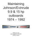
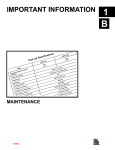
GENERAL INFORMATION AND SPECIFICATIONS
SECTION 1A – GENERAL INFORMATION
AND SPECIFICATIONS
1
A
Table of Contents
How To Use This Manual . . . . . . . . . . . . . . . . . . .
Page Numbering . . . . . . . . . . . . . . . . . . . . . . . . . .
Master Specifications . . . . . . . . . . . . . . . . . . . . . .
Torque Chart . . . . . . . . . . . . . . . . . . . . . . . . . . .
Standard Hardware . . . . . . . . . . . . . . . . . . . . .
Metric Hardware . . . . . . . . . . . . . . . . . . . . . . .
Flushing Cooling System . . . . . . . . . . . . . . . .
Following Complete Submersion . . . . . . . . .
1A-1
1A-2
1A-2
1A-6
1A-6
1A-7
1A-7
1A-8
Out-of-Season Storage . . . . . . . . . . . . . . . . . . 1A-9
Out-of-Season Battery Storage . . . . . . . . . . 1A-10
How Weather Affects Engine
Performance . . . . . . . . . . . . . . . . . . . . . . . . . 1A-11
Detonation: Causes and Prevention . . . . . 1A-11
Compression Check . . . . . . . . . . . . . . . . . . . 1A-12
Water Pressure Check . . . . . . . . . . . . . . . . . 1A-12
How To Use This Manual
The manual is divided into SECTIONS (shown right) which represents major components
and systems.
Some SECTIONS are further divided into PARTS. Each PART has a title page. A Table of
Contents for the particular PART is printed on the back of the title page.
SECTIONS and PARTS are listed on the Service Manual Outline sheet which immediately
follows the cover of this book.
Section
1
2
3
4
5
6
90-858804 AUGUST 1998
Section Heading
General Information/Specifications
Electrical and Ignition
Fuel System and Carburetion
Powerhead
Jet Pump
Sport Jet Installation
Page 1A-1
GENERAL INFORMATION AND SPECIFICATIONS
Page Numbering
Two number groups appear at the bottom of each page. The example below is self-explanatory.
EXAMPLE:
90-826148R1 MAY 1994
Revision No. 1
Page 4A-7
Section Number
Month of Printing
Year of Printing
Part of Section Letter
Page Number
Master Specifications
120
HORSEPOWER
(KW)
Model 120
PH / PUMP
WEIGHT
CYLINDER
BLOCK
STROKE
CYLINDER
BORE
260 lbs.
Type
Displacement
4 Cylinder In-Line
102.9 cu. in. (1687 cc)
Length
2.876 in. (73.05 mm)
Diameter (Standard)
Taper/Out of Round Max.
Bore Type
3.375 in. (85.7 mm)
0.0015
Cast Iron
PISTON
Piston Type
Standard
0.015 in. (0.378 mm) Oversize
0.030 in. (0.752 mm) Oversize
REEDS
Reed Stand Open (Max.)
Page 1A-2
120
(89.5)
Aluminum
Diameter 3.3700 (85.598 mm)
Diameter 3.3850 (85.979 mm)
Diameter 3.4000 (86.360 mm)
0.010 (0.254 mm)
90-858804 AUGUST 1998
GENERAL INFORMATION AND SPECIFICATIONS
PUMP
HOUSING
Gear Ratio
Drive Housing Capacity
Stator Capacity
Pinion Height
Gear Backlash
1.25:1
750 cc
500 cc
0.025 in. (0.64 mm)
0.007 in. - 0.009 in.
(0.177 mm - 0.228 mm)
FUEL
SYSTEM
Fuel
Recommended Gasoline
Recommended Oil
Gasoline/Oil Ratio
Fuel Pressure- @ Idle
- @ WOT
Gasoline and Oil
Automotive Lead-Free: 87 octane minimum
Quicksilver TC-W 3 or TC-W II Outboard Oil
Variable ratio oil injection
3.5 PSI
6 PSI
STARTING
SYSTEM
Electric Start- Starter Draw
Under Load
No Load
Battery Rating
(minimum)
IGNITION
SYSTEM
Type
Spark Plug Type
Spark Plug Gap
Optional (Resistor Plug)
CHARGING
SYSTEM
CARBURETOR
Alternator Output (Regulated)
Idle RPM
Wide Open Throttle (WOT) RPM
Idle Mixture Screw Adjustment
(Preset – Turns Out)
(Preset – All Carbs
Float Setting
Main Jet
– Model 120
– Carb #1
– Carb #2
TIMING
Maximum BTDC
@ Cranking Speed
@ 5000 RPM
Firing Order
– Model 120
90-858804 AUGUST 1998
110 - 200 Amperes
80 - 165 Amperes
670 Marine Cranking Amps (MCA) or
520 Cold Cranking Amps (CCA)
Capacitor discharge
Champion L77JC4
.040 (1.0 mm)
QL77JC4
15 Amp
950 - 1100 RPM
4700 - 5300
1-1/2 turn out from a lightly seated position
Set parallel to body flange
.088
.090
32° BTDC
30° BTDC
1-3-2-4
Page 1A-3
GENERAL INFORMATION AND SPECIFICATIONS
2.910
.020
.77003
.76993
0.15 in.
(3.81 mm)
3.3700
.0005
Measured 90
to piston pin
center line
0.9568
0.9573
4.500
.005
1.4986
1.4991
Page 1A-4
90-858804 AUGUST 1998
GENERAL INFORMATION AND SPECIFICATIONS
1.3748
1.3752
1.2495
1.2500
1.3793
1.3789
1.1813
1.1818
90-858804 AUGUST 1998
CRANKSHAFT
Page 1A-5
GENERAL INFORMATION AND SPECIFICATIONS
Torque Chart
Special Items
Torque
Impeller Shaft Nut
150 lb. ft. (203 N·m)
Drive Housing Cover Bolts
35 lb. ft. (47.5 N·m)
Stator Bolts
35 lb. ft. (47.5 N·m)
Nozzle to Stator Bolts
35 lb. ft. (47.5 N·m)
Rudder Pivot Bolt
20 lb. ft. (27.1 N·m)
Reverse Gate Pivot Bolt
20 lb. ft. (27.1 N·m)
Powerhead to Drive Housing (M8 Nut)
20 lb. ft. (27.1 N·m)
Powerhead to Drive Housing (M10 Nut)
35 lb. ft. (47.5 N·m)
Steering Cable Mounting Bracket
200 lb. in. (22.6 N·m)
Steering Lever Screw
180 lb. in. (20.2 N·m)
Reverse Gate Stop Screw
120 lb. in. (13.6 N·m)
Shift Bracket Screw
50 lb. in. (5.6 N·m)
Inlet Screen Screw
75 lb. in. (8.5 N·m)
Ride Plate Screw
75 lb. in. (8.5 N·m)
Drive Shaft Nut
90 lb. in. (122 N·m)
Cylinder Head
225 lb. in. (25.4 N·m)
Then Turn Additional 90
Flywheel Nut
Main Bearing Bolts
Connecting Rod Screws
125 lb. ft. (169.47 N·m)
270 lb. in. (30.4 N·m)
120 lb. in. (13.6 N·m)
Then Turn Additional 90
Transfer Port Cover
80 lb. in. (9.03 N·m)
Exhaust Manifold
115 lb. in. (13 N·m)
Carburetor Fuel Bowl Screw
30 lb. in. (3.5 N·m)
Standard Hardware
Screw or Nut Size
Page 1A-6
Torque
6 - 32
9 lb. in. (1.0 N·m)
8 - 32
20 lb. in. (2.3 N·m)
10 - 24
30 lb. in. (3.4 N·m)
10 - 32
35 lb. in. (3.9 N·m)
12 - 24
45 lb. in. (5.0 N·m)
1/4 - 20
70 lb. in. (7.8 N·m)
5/16 - 18
160 lb. in. (18.1 N·m)
3/8 - 16
270 lb. in. (30.4 N·m)
90-858804 AUGUST 1998
GENERAL INFORMATION AND SPECIFICATIONS
Metric Hardware
Torque Specification
A
B
lb. in.
lb. ft.
N·m
8 mm
M5
36
3
4
10 mm
M6
70
6
8
12 mm
M8
156
13
18
14 mm
M10
312
26
36
17 mm
M12
372
31
42
A
B
Flushing Cooling System
Flushing the cooling system is essential after each use in salt water, after the boat has run
aground, or when the overheat warning horn sounds (debris in jet powerhead). We recommend using Dealer Kit (P/N 22-820573) to flush the cooling system.
1. Disconnect the inlet water hose at the rear starboard corner of the pump housing. Install
the Dealer Kit and attach water hose.
a
a - Dealer Flushing Kit (22-820573)
2. Turn water on and flush engine block for at least 10 minutes.
3. Remove water hose and dealer flushing kit. Re-install water inlet hose.
4. Flush outer surfaces of water outlet nozzle with water stream.
90-858804 AUGUST 1998
Page 1A-7
GENERAL INFORMATION AND SPECIFICATIONS
Following Complete Submersion
Submerged engine treatment is divided into three distinct problem areas. The most critical
is submersion in salt water; the second is submersion while running; the third is submersion
in fresh water with special instructions.
SALT WATER SUBMERSION (SPECIAL INSTRUCTIONS)
Due to the corrosive effect of salt water on internal engine components complete disassembly is necessary before any attempt is made to start the engine.
SUBMERGED WHILE RUNNING (SPECIAL INSTRUCTIONS)
When an engine is submerged while running, the possibility of internal engine damage is
greatly increased. If, after engine is recovered and with spark plugs removed, engine fails
to rotate freely when turning flywheel, the possibility of internal damage (bent connecting
rod and/or bent crankshaft) exists. If this is the case the powerhead must be disassembled.
SUBMERGED ENGINE (FRESH WATER) PLUS SPECIAL INSTRUCTIONS
1. Recover engine as quickly as possible.
2. Flush exterior of engine with fresh water to remove mud, weeds, etc. DO NOT attempt
to start engine if sand has entered powerhead, as powerhead will be severely damaged.
Disassemble powerhead if necessary to clean components.
3. Remove spark plugs and get as much water as possible out of powerhead by rotating
flywheel.
4. Pour alcohol into carburetor throat (alcohol will absorb water). Again rotate flywheel.
5. Pour alcohol into spark plug openings and again rotate flywheel.
6. Pour engine oil into throats of carburetors while rotating flywheel to distribute oil throughout crankcase.
7. Pour approximately one teaspoon of engine oil into each spark plug opening. Rotate flywheel to distribute oil in cylinders.
8. Remove and clean carburetors and fuel pump assembly.
9. Reinstall spark plugs, carburetors and fuel pump.
10. Attempt to start engine, using a fresh fuel source. If engine starts it should be run for at
least one hour to eliminate any water in engine.
11. If engine fails to start determine cause (fuel, electrical or mechanical). Engine should
be run within two hours after recovery from water as serious internal damage may occur.
If unable to start engine in this period disassemble engine and clean all parts and apply
oil as soon as possible.
Page 1A-8
90-858804 AUGUST 1998
GENERAL INFORMATION AND SPECIFICATIONS
Out-of-Season Storage
WARNING
As a safety precaution, when boat is in storage, remove positive (+) battery cable.
This will eliminate possibility of accidental starting of engine and resultant overheating and damage to engine from lack of water.
In preparing for out-of-season storage, two precautions must be considered: 1) The engine
must be protected from physical damage caused by freezing trapped water and 2) the engine must be protected from rust, corrosion and dirt.
The following storage procedures should be followed to prepare the Sport Jet for out-of-season storage or prolonged storage (two months or longer).
CAUTION
Never start or run the Sport Jet (even momentarily) out of the water. Damage to the
pump and engine will occur.
FUEL SYSTEM
IMPORTANT: Gasoline containing alcohol (ethanol or methanol) can cause a formation of acid during storage and can damage the fuel system. If the gasoline being
used contains alcohol, it is advisable to drain as much of the remaining gasoline as
possible from the fuel tank, remote fuel line, and engine fuel system.
Fill the fuel system (tank, hoses, fuel pump, and carburetors) with treated (stabilized) fuel
to help prevent formation of varnish and gum. Proceed with the following instructions.
•
Portable Fuel Tank: Pour the required amount of Quicksilver Gasoline Stabilizer (follow
instructions on container) into fuel tank. Tip fuel tank back and forth to mix stabilizer with
the fuel.
•
Permanently Installed Fuel Tank: Pour the required amount of Quicksilver Gasoline Stabilizer (follow instructions on container) into a separate container and mix with approximately one quart (one liter) of gasoline. Pour this mixture into fuel tank.
•
Place the Sport Jet in the water. Run the engine for ten minutes to allow treated fuel to
reach the carburetors.
1. With Sport Jet in the water, start the engine and let it warm up to operating temperature.
2. Disconnect the fuel line. When the engine starts to stall quickly spray Quicksilver Storage Seal into each carburetor throat. Continue to spray until engine dies from lack of
fuel.
3. Remove spark plugs and inject a five second spray of Quicksilver Storage Seal around
the inside of each cylinder. Manually turn engine over several times to distribute Storage
Seal throughout cylinders. Reinstall spark plugs.
4. Drain and refill drive housing unit and stator assembly with Quicksilver Hi Performance
Gear Lube as explained in “Jet Pump” section (see Table of Contents).
5. Clean engine thoroughly including all accessible powerhead parts and spray with Corrosion and Rust Preventive.
6. Remove water inlet hose and drain any trapped water. Reconnect hose.
90-858804 AUGUST 1998
Page 1A-9
GENERAL INFORMATION AND SPECIFICATIONS
a
a - Water Inlet Hose
7. Lubricate all lubrication points.
8. To prevent freeze damage, drain the speedometer system of water completely before
storage. Remove tubing from speedometer fitting and blow through tubing to remove
water.
9. Store battery as outlined in Out-of-Season Battery Storage following:
IMPORTANT: Check and refill housings with Quicksilver Hi Performance Gear Lube
before storage to protect against possible water leakage into housings which is
caused by loose lubricant vent plug or loose grease fill plug. Inspect gaskets under
lubricant vent and fill plugs replacing any damaged gaskets before reinstalling
plugs.
Out-of-Season Battery Storage
1. Remove battery as soon as possible and remove all grease, sulfate and dirt from top
surface.
2. Cover plates with distilled water, but not over 3/16 in. (5 mm) above perforated baffles.
3. Cover terminal bolts well with grease.
4. Store battery in a cool, dry place in a dry carton or box.
5. Remove battery from storage every 60 days. Check water level and place on charge for
5 to 6 hours at 6 amperes. DO NOT fast charge.
CAUTION
A discharged battery can be damaged by freezing.
Page 1A-10
90-858804 AUGUST 1998
GENERAL INFORMATION AND SPECIFICATIONS
How Weather Affects Engine Performance
It is a known fact that weather conditions exert a profound effect on power output of internal
combustion engines. Therefore, established horsepower ratings refer to the power that the
engine will produce at its rated RPM under a specific combination of weather conditions.
Corporations internationally have settled on adoption of I.S.O. (International Standards Organization) engine test standards as set forth in I.S.O. 3046 standardizing the computation
of horsepower from data obtained on the dynamometer correcting all values to the power
that the engine will produce at sea level at 30% relative humidity at 77° F (25° C) temperature and a barometric pressure of 29.61 inches of mercury.
Summer Conditions of high temperature, low barometric pressure and high humidity all
combine to reduce the engine power. This, in turn, is reflected in decreased boat speeds--as
much as 2 or 3 miles-per-hour (3 or 5 km per hour) in some cases. Nothing will regain this
speed for the boater, but the coming of cool, dry weather.
In pointing out the practical consequences of weather effects, an engine running on a hot,
humid, summer day may encounter a loss of as much as 14% of the horsepower it would
produce on a dry, brisk spring or fall day. The horsepower that any internal combustion engine produces depends upon the density of the air that it consumes and, in turn, this density
is dependent upon the temperature of the air, its barometric pressure and water vapor (or
humidity) content.
Detonation: Causes and Prevention
Detonation in a 2-cycle engine somewhat resembles the “pinging” heard in an automobile
engine. It can be otherwise described as a tin-link “rattling” or “plinking” sound.
Detonation generally is thought of as spontaneous ignition, but it is best described as a noisy
explosion in an unburned portion of the fuel/air charge after the spark plug has fired. Detonation creates severe, untimely shock waves in the engine and these shock waves often find
or create a weakness: the dome of a piston, piston rings or piston ring lands, piston pin and
roller bearings.
While there are many causes for detonation in a 2-cycle engine emphasis is placed on those
causes which are most common in marine 2-cycle application. A few which are not commonly understood are:
1. Over-advanced ignition timing.
2. Use of low octane gasoline.
3. Lean fuel mixture at or near wide open throttle.
4. Spark plugs (heat range too hot, incorrect reach, cross-firing).
5. Inadequate engine cooling (deteriorated cooling system).
6. Combustion chamber/piston deposits (result in higher compression ratio).
Detonation usually can be prevented provided that (1) the engine is correctly set up and (2)
diligent maintenance is applied to combat the preceding detonation causes listed.
90-858804 AUGUST 1998
Page 1A-11
GENERAL INFORMATION AND SPECIFICATIONS
Compression Check
1. Remove spark plugs.
2. Install compression gauge in spark plug hole.
3. Hold throttle plates at W.O.T.
4. Crank engine through at least four compression strokes to obtain highest possible reading.
5. Check and record compression of each cylinder. Variation of more than 15 psi (103.5
kPa) between cylinders indicates that lower compression cylinder is in some way defective such as worn or sticking piston rings and/or scored piston and cylinder.
6. Compression check is important because an engine with low or uneven compression
cannot be tuned successfully to give peak performance. It is essential, therefore, that
improper compression be corrected before proceeding with an engine tune-up.
7. Cylinder scoring: if powerhead shows any indication of overheating, such as discolored
or scorched paint, visually inspect cylinders for scoring or other damage as outlined in
Section 4: Powerhead.
Water Pressure Check
NOTE: To perform these checks a Water Pressure Gauge Kit P/N 91-79250A2 is recommended.
1. Water pressure at idle in NEUTRAL, is 1/2–1-1/2 psi (3.4-10.3 kPa).
2. Water pressure in FORWARD gear at 5000 RPM is 10-15 psi (69-103.5 kPa).
CAUTION
Static test requires the boat be stationary in the water secured to a dock or trailer
and run in forward. Do not use a flushing device for this test.
Page 1A-12
90-858804 AUGUST 1998