1
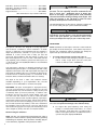
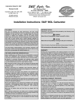
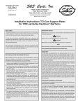
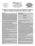
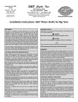
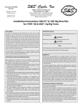
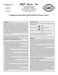
S&S Cycle, Inc.
®
Instruction 51-1196
4-7-06
Copyright © 2001, 2004, 2006
235 Causeway Blvd.
La Crosse, Wisconsin 54603
by S&S Cycle, Inc.
Phone: 608-627-1497 • Fax: 608-627-1488
All rights reserved.
Printed in the U.S.A.
Technical Service Phone: 608-627-TECH (8324)
Technical Service Email: [email protected]
Website: www.sscycle.com
Because every industry has a leader
Installation Instructions: S&S® Super D Gasoline Carburetor
DISCLAIMER:
IMPORTANT NOTICE:
S&S parts are designed for high performance, off road, racing
applications and are intended for the very experienced rider only. The
installation of S&S parts may void or adversely effect your factory
warranty. In addition such installation and use may violate certain
federal, state, and local laws, rules and ordinances as well as other laws
when used on motor vehicles used on public highways, especially in
states where pollution laws may apply. Always check federal, state, and
local laws before modifying your motorcycle. It is the sole and exclusive
responsibility of the user to determine the suitability of the product for
his or her use, and the user shall assume all legal, personal injury risk and
liability and all other obligations, duties, and risks associated therewith.
Statements in this instruction sheet preceded by the following words
are of special significance.
The words Harley®, Harley-Davidson®, H-D®, Sportster®, Evolution®, and
all H-D part numbers and model designations are used in reference only.
S&S Cycle is not associated with Harley-Davidson, Inc.
SAFE INSTALLATION AND OPERATION RULES:
Before installing your new S&S part it is your responsibility to read and
follow the installation and maintenance procedures in these
instructions and follow the basic rules below for your personal safety.
● Gasoline is extremely flammable and explosive under certain
conditions and toxic when inhaled. Do not smoke. Perform installation
in a well ventilated area away from open flames or sparks.
● If motorcycle has been running, wait until engine and exhaust pipes
have cooled down to avoid getting burned before performing any
installation steps.
● Before performing any installation steps disconnect battery to
eliminate potential sparks and inadvertent engagement of starter while
working on electrical components.
● Read instructions thoroughly and carefully so all procedures are
completely understood before performing any installation steps.
Contact S&S with any questions you may have if any steps are unclear
or any abnormalities occur during installation or operation of
motorcycle with a S&S part on it.
WARNING
Means there is the possibility of injury to yourself or others.
CAUTION
Means there is the possibility of damage to the part or motorcycle.
NOTE
Other information of particular importance has been placed in italic type.
S&S recommends you take special notice of these items.
WARRANTY:
All S&S parts are guaranteed to the original purchaser to be free of
manufacturing defects in materials and workmanship for a period of
twelve (12) months from the date of purchase. Merchandise that fails
to conform to these conditions will be repaired or replaced at S&S’s
option if the parts are returned to us by the purchaser within the 12
month warranty period or within 10 days thereafter.
In the event warranty service is required, the original purchaser must
call or write S&S immediately with the problem. Some problems can be
rectified by a telephone call and need no further course of action.
A part that is suspect of being defective must not be replaced by a
Dealer without prior authorization from S&S. If it is deemed necessary
for S&S to make an evaluation to determine whether the part was
defective, a return authorization number must be obtained from S&S.
The parts must be packaged properly so as to not cause further damage
and be returned prepaid to S&S with a copy of the original invoice of
purchase and a detailed letter outlining the nature of the problem, how
the part was used and the circumstances at the time of failure. If after
an evaluation has been made by S&S and the part was found to be
defective, repair, replacement or refund will be granted.
● Consult an appropriate service manual for your motorcycle for correct
disassembly and reassembly procedures for any parts that need to be
removed to facilitate installation.
ADDITIONAL WARRANTY PROVISIONS:
● Use good judgement when performing installation and operating
motorcycle. Good judgement begins with a clear head. Don't let
alcohol, drugs or fatigue impair your judgement. Start installation
when you are fresh.
(2) S&S shall have no obligation if an S&S part becomes defective in
whole or in part as a result of improper installation, improper
maintenance, improper use, abnormal operation, or any other misuse
or mistreatment of the S&S part.
● Be sure all federal, state and local laws are obeyed with the
installation.
● For optimum performance and safety and to minimize potential
damage to carb or other components, use all mounting hardware that
is provided and follow all installation instructions.
(3) S&S shall not be liable for any consequential or incidental damages
resulting from the failure of an S&S part, the breach of any warranties,
the failure to deliver, delay in delivery, delivery in non-conforming
condition, or for any other breach of contract or duty between S&S and
a customer.
● Motorcycle exhaust fumes are toxic and poisonous and must not
be inhaled. Run motorcycle in a well ventilated area where fumes
can dissipate.
(4) S&S parts are designed exclusively for use in Harley-Davidson® and
other American v-twin motorcycles. S&S shall have no warranty or
liability obligation if an S&S part is used in any other application.
(1) S&S shall have no obligation in the event an S&S part is modified by
any other person or organization.
1
Carb Only – (1.937-inch venturi) .............................PN 11-0112
Carb Only – (2.150-inch venturi) .............................PN 11-0128
Carb Kit With Air Horn ............................................PN 11-0110
Support Bracket........................................................PN 16-0471
(Recommended for any D Carb installation)
CAUTION
The heat generated during polishing and chrome plating
processes can alter operating tolerances machined into the
parts in critical areas. Additionally, pieces of chrome may
break off and plug a passageway which could potentially
affect the fuel mixture resulting in damage to the engine. S&S
voids any warranty if the carb body or bowl has been
polished, chrome plated or altered in any way.
Throttle Requirements: An S&S Super D carburetor requires the
use of a two cable, pull open - pull closed throttle assembly.
WARNING
Single, braided wire cable throttle mechanisms can not
mechanically close the throttle. If your throttle inadvertently
sticks in the open position, you could lose control of the
motorcycle and personal injury to you or others may result.
INSTALLATION
The Super D carburetor was designed for racing applications
and should be considered a custom installation. A certain
amount of fabrication and engineering will be required to
adapt this performance carburetor to your motorcycle. It is
delivered in a state of basic tune to help you start the
motorcycle after installation, but final tuning to match your
bike will be required. If you do not feel comfortable with the
steps required in this installation, please visit www.sscycle.com
or call the S&S® Tech Line at (608) 627-TECH for a recommended
shop in your area.
NOTE: Installation of S&S Super D carb kits is easier with the
gas tank(s) off of the motorcycle. Some owners may elect to
perform this installation without removing gas tank(s)--an
option left up to the discretion of the technician.
1.
IDLE SPEED AND MIXTURE SETTINGS FOR START UP
A. Set idle mixture screw setting by turning it clockwise
until it is fully closed. Now open the screw (turn
counter-clockwise) 11⁄2 turns. See Photo 1.
Your S&S Super D carburetor is designed exclusively for large
displacement big twin engines. It is a butterfly carb with a fully
adjustable idle mixture screw with replaceable mid range and
high speed jets. Additionally, it has a tuneable air bleed circuit.
It doesn’t have an accelerator pump or a conventional choke,
instead it utilizes a mixture enrichment device for starting.
The Super D has both a 1.937- and 2.150-inch venturi
available—depending on your requirements. Also, the S&S
Super D is not recommended for use with a fuel pump.
DISCLAIMER: S&S parts are designed for high performance,
off road, racing applications and are intended for the very
experienced rider only. The installation of S&S parts may void
or adversely affect your factory warranty. In addition such
installation and use may violate certain federal, state, and
local laws rules and ordinances as well as other laws when
used on motor vehicles used on public highways, especially in
states where pollution laws may apply. Always check federal,
state, and local laws before modifying your motorcycle. It is
the sole and exclusive responsibility of the user to determine
the suitability of the product for his or her use, and the user
shall assume all legal, personal injury risk and liability and all
other obligations, duties, and risks associated therewith.
Chrome Plating the Carburetor
NOTE: S&S does not recommend chrome plating the Super D
carburetor. In order to achieve a quality chrome finish, polishing
and buffing are required. These operations invariably plug air
or fuel feed holes, regardless of the precautions taken.
2
Photo 1
CAUTION
Use caution closing the idle mixture screw; using too much
force can cause permanent damage to the carburetor body.
B.
Set engine idle speed adjusting screw setting by
turning it counterclockwise until there is no contact
with carburetor body. Next, turn it clockwise until it
makes contact again, and turn one additional 1⁄2 turn to
open throttle plate slightly. See Photo 2.
WARNING
If throttle does not return to fully closed position when
released, it may inadvertently stick open possibly causing loss
of control of motorcycle and personal injury to you or others.
C.
6.
Photo 2
2.
PREPARE AIR CLEANER BACKPLATE
A. The backplate is a custom application based on your
motorcycle. Determine your choice of breather (head
or case) and drill the backplate accordingly.
B. Use of an Air Horn is a custom application based on
your motorcycle’s set up.
3.
INSTALL NEW MANIFOLD
A. Verify that intake ports are clean and ready for
installation.
B. Position manifold with VOES (if equipped) facing up.
Do not tighten bolts at this time.
4.
INSTALL CARB
A. Position carb on intake manifold using two 3⁄8-16 x 1"
socket cap screws provided—do not tighten yet.
B. If you are using a backplate and head breathers, now
is the time to position them.
C. Tighten manifold to heads and then carb to manifold.
NOTE: this is easiest with a 6-inch ball-head Allen.
D. Remove backing plate for throttle cable installation.
CAUTION
1.
2.
Apply a thin coat of oil to the fuel inlet fitting and slide
the 90° bend portion of the fuel line in place. Slide
hose clamp in place and secure. Slip protective fuel line
covering over fuel line and position in a way where
there will be no contact with other engine parts.
Connect other end of the fuel line to petcock using the
clamp provided.
INSTALL AIR CLEANER BACKPLATE/AIR HORN
A. Since this is a custom application, install backing plate
according to your design.
B. If you are using a filter element and air cleaner cover,
install them now.
C. Check fuel needle and seat assembly to be sure it
works properly. Add enough gas to tank(s) to test the
system. Lean the motorcycle over on the carburetor
side, turn the fuel supply valve on and wait 20 seconds.
If gas starts running out of the carb, turn off petcock
and check needle and seat.
WARNING
Fuel needle and seat assembly must completely shut off the
fuel supply entering the float bowl and not leak. Gasoline leaks
at the fuel line connections or past the inlet needle may flood
engine and overflow on surrounding area creating fire hazard.
7.
CARB OPERATION
A. This carburetor does not have a conventional choke.
Instead, a mixture enrichment device that uses
utilizes separate air and fuel pickup passageways
aides in starting.
B. This device is engaged by raising the lever on top left
side of carburetor and rotating it to position. See
Photo 3.
If you install mounting screws that are too long, they
may bottom without fully tightening. Also, they may
contact the carb bowl or body causing damage and
potential failure.
An improperly mounted carburetor could come loose
causing air leaks, poor performance, and damage to
carburetor or other components.
WARNING
If your motorcycle were to fall over or sustain damage in a
collision, an improperly mounted carburetor could break free
causing a release of gasoline to the surrounding area creating
a fire hazard and potential personal injury to you or others.
5.
ROUTE THROTTLE CABLES
A. Since this is a custom application, it is up to you to
determine the appropriate length and routing of
both cables.
B. Ensure that cables do not bind by turning the handlebars
full-lock to each side and operating the throttle. It should
open smoothly with no resistance and snap shut.
Photo 3
3
NOTE: The enrichment pickup tube that is located directly below
the fast idle plunger is pressed into carburetor body and must
not be removed.
CAUTION
Removal of enrichment/fast idle pickup tube from the
carburetor body may alter its hole size in the main body and
cause irreversible damage to carburetor.
COLD START
1. Open fuel supply valve.
2. Pull enrichment device handle up.
3. Turn on ignition.
4. With throttle closed or just slightly open, press starter
button, cranking for no more than 5 seconds at a time.
If engine fails to start immediately, slowly open
throttle enough to slightly open the butterfly and
crank starter until engine fires.
5. Once the engine starts leave the enrichment device on
until engine has warmed. If you feel it is necessary,
open throttle slightly to keep the engine running.
The actual intermediate jet size installed in your carburetor is
indicated on a tag attached or labeled on the box. Keep this
information handy for future reference.
HOT START
1. Open fuel petcock.
2. Turn on ignition.
3. With throttle closed engage electric starter.
4. If engine fails to start immediately, open throttle
slightly and continue to engage starter until the
engine fires.
4.
ADJUSTING THE IDLE CIRCUIT
The idle mixture screw regulates the air/fuel mixture at idle
speeds and works in conjunction with the throttle stop/engine
rpm adjustment screw that is located on the throttle arm. Your
Super D carb is delivered with settings that should work for
initial start-up, but will require adjustment and tuning specific
to your motorcycle.
1. Start engine and let it run for a few minutes until it is
at operating temperature.
2. Initially adjust engine rpm to idle to approximately
950-1000 rpm.
3. Turn the idle mixture screw clockwise--to lean the
mixture--until the engine starts to die. Now turn the
screw counterclockwise--richening the mixture--until
the engine starts to die. Keep track of the distance
(number of turns) between the two points and turn it
back to the mid-point.
Photo 4
1.
2.
3.
5.
6.
Run the bike enough for the engine and oil to reach
normal operating temperature.
Verify idle mixture settings again.
Go on a road test to check carburetion characteristics.
Maintain a steady speed of 30-, 40- and 50-mph. Once you
set your speed, if you feel or hear popping or backfiring in
the aircleaner, the bike is too lean. Correct this by installing
the next larger jet size in the kit.
If the bike accelerates sluggishly or you notice black smoke
from the exhaust, the jetting is too rich. Correct this by
installing the next smaller size jet in the kit.
Repeat the road test procedure. The smallest intermediate
jet that eliminates the popping and provides the best
throttle response should also provide the best fuel economy.
Adjust idle circuit as necessary.
MAIN JET/HIGH SPEED CIRCUIT
The high speed circuit—controlled by the main jet--begins
around 3000-3500 rpm or 55-60 mph and runs to your
motorcycle’s maximum speed. You can access the main jet by
removing the float bowl plug. See Photo 5.
NOTE: Whenever intermediate jet change is made, idle
mixture screw must be readjusted.
INTERMEDIATE CIRCUIT
The intermediate range is used in most normal riding
conditions, beginning right off idle and going up until 30003500 rpm depending on the gearing in your motorcycle. For
that reason, you must pay close attention to jetting your
intermediate circuit to achieve optimum performance and best
gas mileage. You can access the intermediate jet by removing
the float bowl assembly. Photo 4
4
Photo 5
The actual main jet size installed in your carburetor is indicated
on a tag attached or labeled on the box. Keep this information
handy for future reference.
Determining your main jet size is best determined at a drag strip
because maximum miles per hour and rpm are the best indicators
of the actual horsepower your engine is developing. A dyno will
help you get a good baseline, but the drag strip will assure you
the best performance of your racing carburetor.
NOTE: S&S® has a special main jet tool, PN 53-0452, which is
JETTING SIZES
perfect for this operation.
DRAGSTRIP PROCEDURE
1. Warm up engine enough to make a pass.
2. Make a run noting engine rpm and top speed.
3. Richen main jet size .004 larger and make a second run.
Again, note rpm and final speed.
4. Continue procedure until top speed starts to fall.
5. Lean main jet size by .002 to gain the best performance
from the last pass. When you are making runs, do not be
concerned with elapsed time, rather with consistent
miles per hour.
STREET PROCEDURE
S&S uses what we call the RPMing method to determine your
correct main jet size on the street. By performing hard
acceleration tests, noting rpm at which power starts to fall off
and a gear change is necessary, you will determine what jet
offers the best performance.
1. Warm engine to operating temperature.
2. Accelerate rapidly through the gears noting how
quickly--and smoothly—your engine reaches an rpm
level where power starts to fall off and a gear change
becomes necessary.
3. If the engine backfires in carburetor, breaks up or dies
during acceleration, richen the main jet size .004 larger
and road test it again.
4. If engine runs sluggish or will not take throttle, lean
the main jet size by .004 smaller and road test again.
Note your engine’s smoothness and how easily it
accelerates to shift points.
5. Determine the best jet size by matching up acceleration
feel to an rpm level that continues to produce power
as you change into the next gear.
ADJUSTABLE AIR BLEED
The main air bleed passage in an S&S Super D carburetor is
equipped with a .040" jet. By allowing the jet size to be
changed you can fine tune the transition from intermediate
circuit to the main jet to match your motorcycle.
Changing the air bleed jet should only be done after you are
absolutely sure that you cannot tune a rideability problem out
by changing the intermediate and main jets. Shifting the start
of the main jet’s operation higher up the rpm scale can lessen
the effects of mid-range problems created by mismatched cam
and pipe combinations. See Photo 6.
Typical Jetting
124 SSW + .032 Intermediate
.098 Main .040 Air Bleed
145 SSW+ .032 Intermediate
.102 Main .040 Air Bleed
NOTE: A number of racing combinations have allowed the
use of up to a .120 Air Bleed.
NOTES: General Information
1. Carburetor body has seven drilled passages that are
permanently sealed with drive plugs. Do not attempt to
remove these plugs as irreversible damage to carburetor
may result.
2. If the throttle arm is removed from it’s shaft, it must be
reinstalled in wide open position with throttle plate at 90˚
to the fully closed position.
3. The throttle plate should be checked annually for signs of
wear. Replace if necessary.
4. To insure proper seal in needle and seat assembly, float
hinge, needle lift and needle must work freely and must
not bind. If problem is suspected, remove bowl and check
float movement. If obvious misalignment, binding or
sticking occurs, remove and straighten and reinstall to
attain free movement. Reset float level and double check
for free movement. Float must not contact bowl gasket.
5. Normal float setting is 1⁄32" and should be measured at end
of float opposite needle and seat assembly. To check this
measurement, turn bowl upside down and measure from
bowl gasket surface up to float.
6. On rubber mounted engines, set float where it just misses
bowl gasket, S&S PN 11-2086, when fuel inlet needle is fully
closed and spring in needle is compressed. See Figure 1. To
check, remove bowl and raise float until needle is in closed
position and spring in top of needle is compressed. Highest
part of float should be slightly (approximately 1⁄32") below
bowl gasket surface. Float must not contact bowl gasket.
Float just below gasket surface
(approximately 1/32”)
Spring in needle fully
compressed
Figure 1
Photo 6
5
Replacement Parts
for S&S® Super D Gas and Alcohol Carburetors
1.
Carb body assembly
21⁄4" Super D gas .......................................................11-2181
21. Carb bowl assembly
2 1⁄4" Super D gas - forked mechanism .........................N/A
2.
Throttle shaft - includes throttle plate screws .....11-2184
(Must use bowl, float, and needle w/wire type mechanism.)
3.
Throttle plate screw (5 Pack) ...................................50-0064
2 1⁄4" Super D gas - wire mechanism .......................11-2188
4.
Throttle shaft bushing - for repair only............... 11-2134
22. Bowl plug (5 Pack) ....................................................11-2092
5.
Throttle plate all - 21⁄4" D carbs...............................11-2150
23. Needle - 21⁄4" Super D gas
6.
Throttle return spring (5 Pack).............................. 11-3500
Forked mechanism...................................................11-2095
7.
Throttle arm assembly
21⁄4" Super D gas/alcohol......................................... 11-2148
Wire mechanism.......................................................11-2197
8.
Idle mixture screw (5 Pack) .......................................11-2378
9.
Idle mixture screw spring (10 Pack)..........................11-2060
10. Manifold O-ring .......................................................50-8014
24. Seat - 21⁄4" Super D gas
Forked mechanism .160" I.D...................................11-2065
Wire mechanism .238" I.D. .....................................11-2165
25. Needle & seat assembly fuel/alcohol
11. Insulator block 21⁄4" x 1⁄4" includes O-ring...............16-0499
Carbs with forked float mechanism ............................ N/A
12. Enrichment device....................................................11-2084
Carbs with wire float mechanism ........................11-2130
13. Bowl vent plug (10 Pack) ...........................................50-0151
14. Main discharge tube
2 1⁄4" Super D gasoline...............................................11-2185
15. Main jet/main discharge air bleed
State size - see jets in fuel system section
Not Shown:
26. 1" Spacer block, Super D.........................................16-0157
27. Air horn 4 1⁄4" long ....................................................17-0141
16. Intermediate jet- State size - See jets in race section.
28. Air cleaner, Super D .................................................17-0198
17. Bowl gasket - 21⁄4" Super D gas/alcohol (5 Pack) ...11-2092
29. Fuel line 1⁄4" ID w/90° bend,19" ..............................19-0475
18. Float
All carbs with forked mechanism ................................ N/A
All carbs with wire mechanism ..............................11-2187
19. Float retaining pin 21⁄4" Super D gas/alcohol ........11-2069
20. Bowl screw 10-24 x 3⁄4" (10 Pack)...............................50-0063
Super D Gas Carburetor
Years Produced - 1983-up
Size Produced - 21⁄4" Throat
Identification Markings:
● Serial number stamped on body above "S&S Super".
● "D" and "181" cast on body below "S&S Super".
Distinguishing Characteristics:
6
●
Enrichment starting system.
●
Donut shaped float.
●
.235" I.D. fuel inlet.
●
Bowl vented out air cleaner end of carb.
●
Designed for two throttle cables–air cleaner/air horn
mounting pattern different from stock.
12
3
6
8
10
2
9
4
15
10
5
13
11
7
1
14
16
15
17
18
18
19
21
20
23
22
23
24
24
7
Because every industry has a leader