1
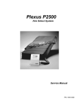
FORM #4681.02-101011 PRINTED IN U.S.A. PAGE 1 OF 13 Superlift® 6” lift system for 2003-2013 Dodge Ram 3/4-ton and 1-ton 4WD INSTALLATION INSTRUCTIONS INTRODUCTION Installation requires a professional mechanic. Prior to beginning, inspect the vehicles steering, driveline, and brake systems, paying close attention to the suspension link arms and bushings, anti-sway bars and bushings, tie rod ends, pitman arm, ball joints and wheel bearings. Also check the steering sector-to-frame and all suspension-to-frame attaching points for stress cracks. The overall vehicle must be in excellent working condition; repair or replace all worn parts. Read instructions several times before starting. Be sure you have all needed parts and know where they install. Read each step completely as you go. NOTES: • IMPORTANT: If the vehicle is equipped with a manual transmission, a transfer case indexing ring (Part # 4663) may be required to alleviate front driveline vibration. The indexing ring is sold separately and includes its own instruction form. • Models equipped with a gas engine, exhaust modifications may be required for front driveshaft clearance. If necessary, the vehicle can be driven a short distance to have the exhaust work performed once the installation is complete. • Special tools are recommended to detach/attach the pitman/idler studs. Refer to the factory service manual. • Front end realignment is necessary. • An arrow on diagrams indicates which direction is toward the front of the vehicle. • A foot-pound torque reading is given in parenthesis ( ) after each appropriate fastener. • Do not fabricate any components to gain additional suspension height. • Prior to drilling or cutting, check behind the surface being worked on for any wires, lines, or hoses that could be damaged. • After drilling, file smooth any burrs and sharp edges. • Paint or undercoat all exposed metal surfaces. • Prior to attaching components, be sure all mating surfaces are free of grit, grease, undercoating, etc. • A factory service manual should be on hand for reference. • Use the check-off box “” found at each step to help you keep your place. Two “” denotes that one check-off box is for the driver side and one is for the passenger side. Unless otherwise noted, always start with the driver side. PARTS LIST … The part number is stamped into each part or printed on an adhesive label. Identify each part and place the appropriate mounting hardware with it. FORM #4681.02-101011 PART NO. PRINTED IN U.S.A. PAGE 2 OF 13 DESCRIPTION ATTACHING HDW. (Qty.- if more than one) (Qty.) HDW. BAG 01-246 or 247 .............. front coil spring, driver side 02-246 or 247............... front coil spring, passenger side 55-16-4681 .................. (2) lower link arm ......................... (4) bushing half……………… 77-4640 (2) 1-1/8” OD x 2-1/2” sleeve 55-15-4681 .................. (2) upper link arm ........................ (4) bushing half……………… 77-4640 (2) 1” OD x 2-1/4” sleeve (1) 14mm x 150mm bolt 77-4670 01-4011 ....................... pitman arm ……………..………… (1) cotter pin…………………..77-4650C 55-05-4680 .................. front track bar bracket.................. (2) 5/8” x 3-1/4” bolt …………77-4680 (2) 5/8” Stover nut (4) 5/8” SAE washer (1) 1/2” x 3” bolt (1) 1/2” x 1-1/4” bolt (1) 1/2” USS washer (2) 1/2” Stover nut (1) 3/4” ID x 1-3/8” sleeve (1) square washer 55-07-4680……………. stabilizer bar drop bracket, dr…… (2) 3/8” x 1” bolt……………… 77-4680 (2) 3/8” Flange nut (2) 3/8” SAE washer 55-08-4680……………. stabilizer bar drop bracket, pa….. (2) 3/8” x 1” bolt……………… 77-4680 (2) 3/8” Flange nut (2) 3/8” SAE washer 01-306…………………..(2) compression travel……………(2) 10mm Nyloc nut…………….77-4670 dampener, front 55-25-4660 .................. (2) compression travel dampener bracket, front 55-24-4640 .................. (2) compression travel…………….(4) 3/8” x 1-1/4” bolt……………77-4670 dampener nut plate, front (4) 3/8” lockwasher 55-27-4660 .................. brake hose relocation……………. (1) 5/16” x 3/4” bolt……………..77-4670 bracket, front driver side (1) 5/16” SAE washer (1) 5/16” Nyloc nut FORM #4681.02-101011 PART NO. PRINTED IN U.S.A. PAGE 3 OF 13 DESCRIPTION ATTACHING HDW. (Qty.- if more than one) (Qty.) HDW. BAG 55-28-4660 ................. brake hose relocation……………. (1) 5/16” x 3/4” bolt……………..77-4670 bracket, front passenger side (1) 5/16” SAE washer (1) 5/16” Nyloc nut 55-03-4660 .................. emergency brake cable drop ........ (2) 3/8” x 1-1/4” bolt…………….77-4670 bracket (2) 3/8” SAE flat washer (2) 3/8” Nyloc nut (2) 5/16” x 1” self-tapping bolt 55-11-4660 ................. (2) compression travel.................. (4) 3/8” x 1-1/4” bolt…………..77-4670 .................................... dampener bracket, rear ................ (4) 3/8” USS washer (4) 3/8” Nyloc nut 55-18-4660 .................. automatic transmission drop ........ (2) 10mm nut bracket, diesel OR 55-19-4660 .................. transmission drop bracket, ........... (2) 10mm nut gas V-8 55-21-4660 .................. E-brake cable ............................... (1) 1/4” x 1” bolt………………....77-4670 extension bracket, rear (1) 1/4” USS washer (1) 1/4” Nyloc nut (1) 5/16” x 1” self-tapping bolt 55-15-4680 .................. rear brake hose bracket spacer (2) shock absorber, front ............... (2) hardware pack and cable tie Shock numbers depend on type ordered. (2) shock absorber, rear ................ (2) hardware pack and cable tie (4) 3/4” SAE washer 0034............................. Superlift® badge ........................... alcohol wipe pad 00461........................... decal, "Warning To Driver" FRONT DISASSEMBLY NOTE: Save all factory components and hardware for reuse, unless noted. 1) PREPARE VEHICLE... Place vehicle in neutral. Raise front of vehicle with a jack and secure a jack stand beneath each frame rail, behind the lower link arms. Ease the frame down onto the stands, place transmission in low gear or “park”, and chock rear tires. Position the jack so that it supports, but does not raise, the front axle. Remove front tires. 2) ANTI-SWAY BAR LINKS… Disconnect the anti-sway bar links from the bar body. 3) SHOCK ABSORBERS… Remove the lower shock bolt, followed by the bolts attaching the shock tower-to-coil tower. Remove the shocks. FORM #4681.02-101011 PRINTED IN U.S.A. PAGE 4 OF 13 4) TRACK BAR… Disconnect the track bar from its upper (frame) mounting point, and rest it on the axle. It may be helpful to loosen the lower track bar bolt to relax the lower bushing. 5) DRAG LINK… Remove the cotter pin and castellated nut from the drag link where it attaches to the pitman arm. Using the appropriate tool, separate the drag link from the pitman arm. 6) BRAKE HOSES… Remove the brackets securing the brake hoses to the rear of the lower link arm bracket at the axle. 7) COIL SPRINGS… Ease down the jack supporting the front axle enough to facilitate removing the springs. 8) COMPRESSION TRAVEL DAMPENERS… Remove. 9) PITMAN ARM… Note the orientation of the pitman arm in relation to the steering sector, then remove the nut securing the pitman arm to the steering sector shaft. Using the appropriate puller tool, detach the pitman arm from the sector shaft. Align the indexing splines of the Superlift® pitman arm with the steering sector shaft then secure using the factory hardware. Tighten (225). 10) MARKING ECCENTRIC CAM BOLT LOCATION… The lower trailing links (one on each side) are secured to the axle via eccentric cam bolts. Rotating these bolts changes front axle alignment. It is important that the eccentrics be installed in exactly the same position as they were removed to serve as a baseline for final alignment. Scribe a line on each eccentric, and the flanges they contact, for reference during reassembly. 11) UPPER AND LOWER LINK ARMS… Perform this step one side at a time. NOTE: If the optional Rockrunner adjustable links have been purchased, install now per separate instructions. Remove the bolts securing the factory upper and lower link arms to the frame and axle. NOTE: On vehilces with diesel engines, the exhaust system interfers with the removal of the bolt. Follow these instructions: Loosen the bolt and remove nut. Slide the bolt out enough to cut with a Sawz-all. Using vise-grips, clamp down securely on the bolt so that it will not spin. Cut the head of the bolt off with Sawz-all. Remove cut bolt from frame, retain the factory nut. When reattaching arm in later step, install bolt from the outside. IMPORTANT: Lubricate, with a lithium grease, only the bushing area where the sleeve makes contact and the side of the bushings, do not lubricate the area of the bushings that contact the link eye. Insert the bushing halves and sleeves into the upper and lower link arms. Note that the 2- FORM #4681.02-101011 PRINTED IN U.S.A. PAGE 5 OF 13 1/2” long sleeves install in the lower links, while the 2-1/4” long sleeves install in the upper links. Install the Superlift® link arms using the factory hardware. When the eccentric cam bolts are reinstalled in the lower link arms (at axle end), be sure to align the marks made previously. Snug-up, but do not tighten bolts at this time. NOTE: Be sure the Superlift® link arms are positioned properly in their respective lower and upper arm positions. The part numbers are stamped in each arm for reference. Upper link arm center to center length: 18-5/8” Lower link arm center-to-center length: 20-3/8” 12) COMPRESSION TRAVEL DAMPENERS… Perform this step one side at a time. [DIAGRAM 1] Insert one #55-24-4640 nut plate in the factory compression stop cup, located at the bottom of the frame rail. Position the compression dampener bracket (#55-254660) then secure it to the nut plate using the supplied 3/8” x 1-1/4” bolts and lockwashers. Tighten (23). Attach a #01-306 compression travel dampener to the “25” bracket using the supplied 10mm Nyloc nut. Tighten (23). 13) COIL SPRINGS… NOTE: On newer models equipped with a gasoline engine, watch carefully for adequate driveshaft clearance as the axle is lowered to install the coil springs. In some cases it may be necessary to remove the front driveshaft temporarily. It may lso be necessary to dimple or otherwise modify the exhaust for adequate front driveshaft clearance once the installation is complete. The coil springs are side-specific and must be installed correctly; refer to Parts List. Lower the front axle enough to facilitate installation of coil springs. Position the springs in the coil towers then raise the front axle enough to seat and hold them in place. 14) SHOCK ABSORBERS… Install shock bushings, hardware and boots. FORM #4681.02-101011 PRINTED IN U.S.A. PAGE 6 OF 13 Position the shocks inside the coil springs with the stem end of the shock facing upward. Attach the bottom end of the shock using factory hardware. The bottom bolts are not tightened until step 26. Position a washer and bushing on the shock stem then reattach the shock tower to the coil tower using factory hardware (55). Install the remaining bushing and washer on the shock stem and tighten until the bushings swell slightly. 15) TRACK BAR BRACKET… [DIAGRAMS 2, 3] Refer to Diagram 3. Mate the Superlift® track bar bracket to the factory upper track bar mount as shown. The front lip of the Superlift® bracket should be positioned in front of the factory track bar mount and crossmember, while the rear lip of the Superlift® bracket installs in front of the rear lip of the factory track bar mount. In other words, the Superlift® bracket steps forward (toward the front bumper) when viewed from the side of the vehicle. Insert the supplied 3/4” ID x 1-3/8” long sleeve inside the factory mount and align it with the mounting hole. Install the supplied 9/16” or 5/8” x 3-1/4” bolt and Stover nut through the “05” bracket, factory mount, and sleeve, then secure using the supplied 9/16” or 5/8” Stover nut. Snug-up, but do not fully tighten, at this time. Install the 1/2” x 3” bolt through the “05” bracket and the existing slotted hole in the frame crossmember, as shown in Diagram 2. The bolt should be installed from the bottom. Install the supplied square washer and 1/2” Nyloc nut. Tighten the 9/16” (135) or 5/8” bolt (195), then the 1/2” bolt (57). [DIAGRAM 3] Using the “05” track bar bracket as a template, drill a hole in the crossmember using a 17/32” bit, as shown. Install the supplied 1/2” x 1-1/4” bolt through the drilled hole and secure using a 1/2” Nyloc nut (57). NOTE: The track bar is attached to the Superlift® bracket in a later step. 16) BRAKE HOSE BRACKETS… [SEE PHOTO] Position the factory brake hose bracket so that the lower tab of the factory bracket engages the slot of Superlift’s bracket (55-274660 Driver Side and 55-28-4660 Passenger Side). Install the supplied 5/16” x 3/4" bolt through the factory bracket then Superlift’s relocation bracket. Secure using the supplied 5/16” SAE washer and Nyloc nut (200in. lbs.) FORM #4681.02-101011 PRINTED IN U.S.A. PAGE 7 OF 13 ® Position the Superlift bracket so the lower mounting hole lines up with the factory threaded hole in the link arm bracket and secure using the factory bolt (7). 17) STABILIZER BAR DROP BRACKETS… .Note the orientaion of the stabilizer bar body and remove it from the frame. Attach the drop brackets (Driver side #55-07-4680 and passenger side #55-08-4680) to the frame using the factory hardware (30). Reattach the stabilzer bar body to the new brackets using the supplied 3/8” x 1” bolts, washers, and Flange nuts (30). Reattch the stabilizer bar links to the bar using the factory hardward, tighten until the bushings swell slightly. 18) DRAG LINK… Reattach drag link-to-pitman arm using the factory nut and the supplied cotter pin. Tighten (65). REAR PROCEDURE 19) REAR BLOCK KIT… Use a floor jack positioned under the rear axle to raise the vehicle. Place jackstands under the frame rails, a few inches in front of the rear springs’ forward hanger. Ease the jack down until the frame is resting on the stands, but keep a slight load on the jack. If the front has been placed back on the floor, chock the front tires to prevent the possibility of vehicle movement. Remove the tires, U-bolts, and shocks. (See Photo) Remove the axle vent hose from the fitting then remove the vent hose fitting from the axle. This will free the brake hose bracket. Remove the bolt located on the rear of the driver side spring perch that is retaining the brake line and ABS line. Lower the axle by carefully easing down the jack. Do not overextend the brake lines and axle vent hoses. NOTE: The spring perches are prone to collapse or warp where the leaf springs or blocks seat on the axle, especially towards the ends. Without a perfectly flat mounting surface, the block may fail and “roll” out off of the perches. Check to make sure the perches are flat (use a straight-edge) before proceeding. Make sure the top of the spring perches and the bottom of the springs are clean and free of debris. Position the Superlift® blocks in between the leaf springs and the spring perches. Notice that the top of the blocks are flat but have an offset center pin. Position the block so that the center pin is shifted forward. Install the supplied U-bolts and factory U-bolt plates, then torque the bolts using an “X” tightening sequence (106). FORM #4681.02-101011 PRINTED IN U.S.A. PAGE 8 OF 13 20) SHOCK ABSORBERS… Install shock bushings, sleeves (0.75” O.D., 0.563” I.D., 1.68” L) and boots. Install shocks using the factory hardware. On the lower mounts, position 3/4” SAE washers between the mount and the shock bushing, so that the bushing is sandwiched by the washers and shock mount. Shock bolts are tightened in a later step. 21) COMPRESSION TRAVEL DAMPENER BRACKETS… [DIAGRAM 4] Remove the factory dampeners. Attach #55-11-4660 bracket-to-frame using the supplied 3/8” x 1” bolts and Nyloc nuts. The bracket should be positioned so that it steps foreward (toward the front), as shown. Tighten (23). Attach the factory dampeners to the Superlift® brackets using the factory hardware then tighten (30). 22) EMERGENCY BRAKE CABLE BRACKET… NOTE: Avoid damaging any of the cable retaining clips and connectors, and keep all hardware for reuse. Locate the emergency brake cable tensioner assembly on the driver side frame rail just forward of the rear spring hanger. Note that the single cable coming from the pedal inside the cab splits into two cables at the tensioner assembly; one cable goes to the driver side brake and the other to the passenger side brake. Make a note of where these two cables attach to the tensioner assembly. Loosen the adjuster nut enough to unclip the passenger side cable from the cable connector. It will be necessary to bend the small metal tab on the connector with a screwdriver in order to disconnect the cable. Once the passenger side cable is free, unclip the driver side cable from the tensioner assembly. Using a pair of pliers to hold in the prongs of its retaining clip, remove the passenger side cable from the tensioner assembly. Remove the emergency brake cable hanger that is mounted in the driver side rear fender well. Save the hanger and hardware for re-use. Pull both the driver and passenger side cables out of FORM #4681.02-101011 PRINTED IN U.S.A. their respective holes in the frame and then reroute them so that they pass beneath the spring near the rear spring eye. [DIAGRAM 5] Position the #55-03-4660 mounting bracket as shown and loosely secure it to the lower hole in the frame originally used to retain one of the e-brake cables using supplied 3/8” x 11/4” bolt, flate washer, and Nyloc nut. Snug, but do not tighten at this time. Using the “03” bracket as a template, drill a 13/32” hole as shown in Diagram 5. Install the supplied 3/8” x 1-1/4” bolt in the hole just drilled and secure using the supplied flat washer and Nyloc nut. Tighten both 3/8” bolts (23). As noted in Diagram 5, attach the passenger side e-brake cable to the upper hole and the driver side e-brake cable in the lower hole in the “03” bracket. Be sure the prongs of the factory cable retaining clips are spread enough to secure each cable. [DIAGRAM 6] Position the factory e-brake cable hanger on both cables, then locate the hanger on the frame as shown. Drill two pilot holes in the frame using a 17/64” bit, then secure the hanger to the frame using the supplied 5/16” x 1” self-tapping bolts (13). Do not overtighten the 5/16” bolts. [DIAGRAM 7] Position the factory E-brake hanger on both cables, then attach the supplied #55-21-4660 relocation bracket to the hanger using the supplied 1/4” x 1” bolt, washer, and Nyloc nut. Locate the bracket on the frame as shown and drill a 17/64” mounting hole. Secure the bracket to the frame with the supplied 5/16” x 1” self-tapping bolt (13), then tighten the 1/4” bolt (76 in-lb.). Reattach the e-brake cables to the tensioner assembly in the reverse order of how they were removed and adjust the tension of the cables per the procedure found in the factory service manual. 23) BRAKE HOSE AXLE BRACKET... Thread the new brake hose bracket spacer (#55-15-4680) in the factory location. PAGE 9 OF 13 FORM #4681.02-101011 PRINTED IN U.S.A. PAGE 10 OF 13 Carefully straighten the factory hard line to allow enough slack to position the factory brake hose bracket on top of the new spacer. DO NOT KINK THE LINE. Place the factory brake line bracket on top of the new spacer and thread in the vent hose fitting. (40) Reinsert the factroy bolt that retains the brake line to the rear of the spring perch. (35) FINAL PROCEDURES 24) TIRES / WHEELS... [DIAGRAM 8] Install all four tires / wheels. Tighten lug nuts (145) in the sequence shown. WARNING: When the tires / wheels are installed, always check for and remove any corrosion, dirt, or foreign material on the wheel mounting surface, or anything that contacts the wheel mounting surface (hub, rotor, etc.). Installing wheels without the proper metal-to-metal contact at the wheel mounting surfaces can cause the lug nuts to loosen and the wheel to come off while the vehicle is in motion. WARNING: Retighten lug nuts at 500 miles after any wheel change, or anytime the lug nuts are loosened. Failure to do so could cause wheels to come off while vehicle is in motion. 25) INITIAL CLEARANCE CHECK, REAR… With the vehicle still on jack stands, and the suspension “hanging” at full extension travel, check all components for proper operation and clearances. Pay special attention to clearance between the tires / wheels and brake hoses, driveshaft, etc. Remove jack stands and lower vehicle to the floor. 26) INITIAL CLEARANCE CHECK, FRONT… With the vehicle still on jack stands, and the suspension “hanging” at full extension travel, cycle steering lock-to-lock and check all components for proper operation and clearances. Pay special attention to the clearance between the tires / wheels and brake hoses, wiring, etc. Remove jack stands and lower vehicle to the floor. 27) HARDWARE TIGHTENING SEQUENCE… The suspension is now supporting vehicle weight. Align the track bar with its upper attachment hole in the “05” bracket. Secure the bar with either the supplied 9/16” or the 5/8” x 3-1/4” bolt. Tighten 9/16” bolt (135); tighten 5/8” bolt (195). Tighten the track-bar-to-axle bolt if it was loosened (150). Axle-to-frame link arms / upper, both ends (120). Axle-to-frame link arms / lower, both ends (160). NOTE: Position the lower link-to-axle cam bolts in exactly the same position they were removed (reference step 10), then caster and camber are close enough to specifications to drive the vehicle safely and slowly to an alignment facility. Front shocks, lower mounts (89). Rear shocks, upper and lower mounts (100). FORM #4681.02-101011 PRINTED IN U.S.A. PAGE 11 OF 13 28) FINAL CLEARANCE CHECK... With vehicle on floor, cycle steering lock-to-lock and inspect the tires / wheels, and the steering, suspension, and brake systems for proper operation, tightness, and adequate clearance. 29) HEADLIGHTS... Readjust headlights to proper setting. 30) ALIGNMENT / CENTERING THE STEERING WHEEL / FRONT DRIVESHAFT ANGLE… Realign vehicle to factory specifications. A precise alignment, including the centering of the steering wheel, is required. IMPORTANT - [DIAGRAM 9] Relay this information to the alignment shop: In order to achieve proper adjustment sleeve clamping force, clamp / bolt assemblies (found on the drag link and tie rod assemblies) must be positioned as shown. The open side of each clamp must align with the slot in the threaded adjustment sleeve. Improper positioning and bolt torque will promote linkage deflection, which may contribute to tire shimmy. Tighten clamp bolts (45). With the vehicle on the ground and the suspension supporting vehicle weight, observe the angle of the front driveshaft in relation to the front axle pinion. The pinion needs to be close to parallel to the driveshaft (no more than a 1 to 2 degree angle present) or there will be a possibility of driveline vibration. Loosen the cam bolts on the lower link arms and rotate them until the pinion is 1 to 2 degrees down from parallel with the front driveshaft. Tighten the cam bolts (160). Drive the vehicle safely and slowly to an alignment facility. Have the vehicle professionally aligned to factory specifications with the exception of caster, which should be set to: Caster: 4.0° +/-0.5 IMPORTANT: Raising the pinion to match driveshaft angle will decrease caster. There must be at least 3.5 degrees of positive caster present after the correction of the driveshaft angle. If there is not enough caster present after aligning the pinion with the driveshaft, rotate the pinion downward until the minimum caster specification is achieved. 31) SUPERLIFT® WARNING DECAL... Install the WARNING TO DRIVER decal on the inside of the windshield, or on the dash, within driver’s view. Review the “Important Product Use and Safety Information / Warnings” section below. Limited Lifetime Warranty / Warnings Your Superlift® product is covered by the Limited Warranty explained below that gives you specific legal rights. This limited warranty is the only warranty Superlift® makes in connection with your product purchase. Superlift® neither assumes nor authorizes any retailer or other person or entity FORM #4681.02-101011 PRINTED IN U.S.A. PAGE 12 OF 13 to assume for it any other obligation or liability in connection with this product or limited warranty. What is covered? Subject to the terms below, Superlift® will repair or replace its products found defective in materials or workmanship for so long as the original purchaser owns the vehicle on which the product was originally installed. Your warrantor is LKI Enterprises, Inc. d/b/a Superlift® Suspension Systems (“Superlift®”). What is not covered? Your Superlift® Limited Warranty does not cover products, parts or vehicles Superlift® determines to have been damaged by or subjected to: • Alteration, modification or failure to maintain. • Normal wear and tear (bushings, tie-rod ends, etc.). Scratches or defects in product finishes (powdercoating, plating, etc.), • Damage to or resulting from vehicle’s electronic stability system, related components or other vehicle systems. • Racing or other vehicle competitions or contests. Accidents, impact by rocks, trees, obstacles or other aspects of the environment. • Theft, vandalism or other intentional damage. Remedy Limited to Repair / Replacement. The exclusive remedy provided hereunder shall, upon Superlift’s inspection and at Superlift’s option, be either repair or replacement of product or parts covered under this Limited Warranty. Customers requesting warranty consideration should contact Superlift® by phone (1-800-551-4955) to obtain a Returned Goods Authorization number. All removal, shipping and installation costs are customer’s responsibility. If a replacement part is needed before the Superlift® part in question can be returned, you must first purchase the replacement part. Then, if the part in question is deemed warrantable, you will be credited / refunded. Other Limitations - Exclusion of Damages - Your Rights Under State Law • Neither Superlift® nor your independent Superlift® dealer are responsible for any time loss, rental costs, or for any incidental, consequential or other damages you may have. • This Limited Warranty gives you specific rights. You may also have other rights that vary from state to state. For example, while all implied warranties are disclaimed herein, any implied warranty required by law is limited to the terms of our Limited Lifetime Warranty as described above. Some states do not allow limitations of how long an implied warranty lasts and / or do not allow the exclusion or limitation of incidental or consequential damages, so the limitations and exclusions herein may not apply to you. Important Product Use and Safety Information / Warnings As a general rule, the taller a vehicle is, the easier it will roll over. Offset, as much as possible, what is lost in rollover resistance by increasing tire track width. In other words, go “wide” as you go “tall”. Many sportsmen remove their mud tires after hunting season and install ones more appropriate for street driving; always use as wide a tire and wheel combination as feasible to enhance vehicle stability. We strongly recommend, because of rollover possibility, that the vehicle be equipped with a functional roll bar and cage system. Seat belts and shoulder harnesses should be worn at all times. Avoid situations where a side rollover may occur. FORM #4681.02-101011 PRINTED IN U.S.A. PAGE 13 OF 13 Generally, braking performance and capabilities are decreased when significantly larger / heavier tires and wheels are used. Take this into consideration while driving. Also, changing axle gear ratios or using tires that are taller or shorter than factory height will cause an erroneous speedometer reading. On vehicles equipped with an electronic speedometer, the speed signal impacts other important functions as well. Speedometer recalibration for both mechanical and electronic types is highly recommended. Do not add, alter, or fabricate any factory or aftermarket parts to increase vehicle height over the intended height of the Superlift® product purchased. Mixing component brands is not recommended. SUPERLIFT SUSPENSION SYSTEMS 300 Huey Lenard Loop Rd. West Monroe, Louisiana 71292 Phone: (318) 397-3000 Sales / Tech: 1-800-551-4955 FAX: (318) 397-3040 www.superlift.com