1
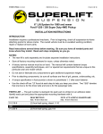
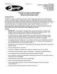
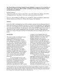
FORM #9690.04-092605 PRINTED IN U.S.A. PAGE 1 OF 16 Superlift 10” lift system for 1999-2004 Ford F-250 / F-350 Super Duty 4WD INSTALLATION INSTRUCTIONS INTRODUCTION Installation requires a professional mechanic. Prior to beginning, inspect the vehicles steering, driveline, and brake systems, paying close attention to the suspension link arms and bushings, anti-sway bars and bushings, tie rod ends, pitman arm, ball joints and wheel bearings. Also check the steering sector-to-frame and all suspension-to-frame attaching points for stress cracks. The overall vehicle must be in excellent working condition; repair or replace all worn parts. Read instructions several times before starting. Be sure you have all needed parts and know where they install. Read each step completely as you go. NOTES: • This lift system only fits Super Duty trucks made on or after 3-1-99. • This kit requires the front driveshaft to be lengthened approximately 2-1/2”. This modification can be performed by any reputable driveshaft shop. • Prior to beginning installation, examine the rear driveshaft of the vehicle and determine if it has a two-piece driveshaft that utilizes a carrier bearing. If the driveshaft is a two-piece design, a carrier bearing drop kit (Superlift #9695) is required. This carrier bearing drop kit is sold separately and includes separate instructions. • Front end realignment is necessary. • An arrow on diagrams indicates which direction is toward the front of the vehicle. • A foot-pound torque reading is given in parenthesis ( ) after each appropriate fastener. • Do not fabricate any components to gain additional suspension height. • Prior to drilling or cutting, check behind the surface being worked on for any wires, lines, or hoses that could be damaged. • After drilling, file smooth any burrs and sharp edges. • Paint or undercoat all exposed metal surfaces. • Prior to attaching components, be sure all mating surfaces are free of grit, grease, undercoating, etc. • A factory service manual should be on hand for reference. • Use the check-off box “” found at each step to help you keep your place. Two “” denotes that one check-off box is for the driver side and one is for the passenger side. Unless otherwise noted, always start with the driver side. FORM #9690.04-092605 PRINTED IN U.S.A. PAGE 2 OF 16 PARTS LIST … The part number is stamped into each part or printed on an adhesive label. Identify each part and place the appropriate mounting hardware with it. PART NO DESCRIPTION NEW ATTACHING HARDWARE (Qty.- if more than one) (Qty.- if more than one) 01-218-6....................... (2) front leaf spring (diesel, V-10) OR 01-219-6....................... (2) front leaf spring (gas V-8) 01-181 .......................... (2) rear spring 01-1112 ........................ pitman arm 01-1115-3..................... drag link adjustment sleeve 55-01-9620................... front spring hanger, driver side 55-02-9620................... front spring hanger, passenger side 55-03-9620................... (2) spring shackle, front ............... (2) 7/16” x 5” bolt (2) 7/16” nyloc nut (2) shackle sleeve 01-300 .......................... (2) poly compression stop, front .. (2) 3/8” lock washer (2) nyloc nut 55-07-9682................... track bar bracket, front 01-9698 ....................... track bar end link, 10” long 02-9698 ....................... track bar end link, 19.5” long 01-1115-3 .................... adjuster sleeve with clamps NOTE: Track bar components are shipped assembled. 55-01-9690 .................. (2) anti-sway bar links, front ........ (4) bushing link (2) sleeve, 12mm ID (2) sleeve, 1/2" ID (2) 1/2" x 2-1/2" bolt (2) 1/2" Nyloc nut 55-02-9690................... anti-sway bar drop bracket, ......... (1) 12mm x 70mm bolt front, passenger side (1) 12mm x 80mm bolt (2) 12mm stover nut 55-03-9690................... anti-sway bar drop bracket, ......... (1) 12mm x 70mm bolt front, driver side (1) 12mm x 80mm bolt (2) 12mm stover nut 55-04-9690................... compression stop extension, ....... (2) 3/8” x 1” bolt front, passenger side (2) 3/8” x 1” nyloc nut 55-05-9690................... compression stop extension, ....... (2) 3/8” x 1” bolt front, driver side (2) 3/8” x 1” nyloc nut FORM #9690.04-092605 PRINTED IN U.S.A. PAGE 3 OF 16 55-06-9690 .................. (2) compression stop plate, rear... (16) 5/8” extra-thick flat washer (8) 5/8” nyloc nut 55-10-9680 .................. front brake line drop bracket, ....... (2) 7/16” x 1-1/4” bolt passenger side (2) 7/16” SAE washer (2) 7/16” nyloc nut 55-11-9680 .................. front brake line drop bracket, ....... (2) 7/16” x 1-1/4” bolt driver side (2) 7/16” SAE washer (2) 7/16” nyloc nut 01-91500 ..................... front brake hose, driver side ......... (2) 7/16” crush washer (1) 3/8” plug 02-91500 ..................... front brake hose, .......................... (2) 7/16” crush washer passenger side 55-07-9620 .................. (2) front bumper spacer................ (4) 12mm x 60mm bolt (4) 7/16” extra-thick flat washer vacuum and breather hose .......... (2) 3/16” x 4” rubber hose extension hardware, front (2) 3/16” plastic connector (1) 5/16” x 9” rubber hose (1) 5/16” plastic connector 55-07-9690 .................. rear shock crossmember .............. (2) 1/2” x 2-1/2” bolt (4) 1/2” x 1/-1/2” bolt (4) 1/2” SAE washer (6) nyloc nut 55-08-9690 .................. (2) rear anti-sway bar link............. (4) bushing (4) sleeve, 12mm ID 55-09-9690 .................. (2) compression stop.................... (2) 7/16” x 2-1/2” bolt extension spacer, rear (4) 7/16” SAE washer (2) 7/16” nyloc nut 55-10-9690 .................. (2) compression stop.................... (4) 1/2” x 1-1/4” bolt extension, rear (4) 1/2” x 1-1/2” bolt (8) 1/2” SAE washer (4) 1/2” nyloc nut (4) 1/2” tab nut 55-13-9690 .................. (2) compression travel stop, ......... (2) 3/8” x 2” bolt rear (2) 3/8” USS washer (2) 3/8” nyloc nut 55-22-4540 .................. brake line drop bracket, rear ........ (1) 5/16” x 3/4” bolt (1) 5/16” SAE washer (1) 5/16” nyloc nut 55-48-3120 .................. 7/16” female / female adapter 55-46-3120 .................. (2) brake line extensions, front, 7/16” fittings 038 .............................. rear block kit ................................. (4) 5/8” x 3-5/8” x 14” U-bolt (8) 5/8” extra-thick flat washer FORM #9690.04-092605 PRINTED IN U.S.A. PAGE 4 OF 16 (8) 5/8” nyloc nut 85160 ........................... (2) shock absorber, front ............. (2) shock boot*, yellow (2) hardware pack and cable tie 85150 ........................... (2) shock absorber, rear .............. (2) shock boot*, yellow (2) hardware pack and cable tie *(Note: Shock boots, if desired, purchased separately) 0034 ............................. Superlift badge ............................ alcohol wipe pad 00461 ........................... decal, "Warning To Driver" FRONT PROCEDURE 1) PREP ARE VEHICLE... Place vehicle in neutral. Raise front of vehicle and secure a jack stand beneath each frame rail, behind the front spring shackles. Ease the frame down onto the jack stands. Leave the jack under the axle to support it while the suspension is disassembled. Place transmission in low gear or “park”, and chock rear tires. Remove front tires. 2) REMOVE FRONT BUMPER... Using a clip tool or a large flat head screwdriver, disconnect the rubber splash panel from beneath the front bumper. Disconnect the block heater plug “Christmas tree” clip from the bumper (if so equipped). Remove the four bumper-to-frame bolts and lay the bumper aside. 3) TRACK BAR / ANTI-SW AY BAR… NOTE: The track bar’s lower end attaches to the passenger side of the front axle. It’s upper end mounts to a bracket that ties into the passenger side frame rail and the primary frame crossmember. Disconnect the track bar from it’s upper and lower mounting brackets and remove the bar. Now unbolt the bar’s upper end mounting bracket. The track bar and mounting bracket may be discarded, but save all hardware for re-use. NOTE: On each side, anti-sway bar links span from the sway bar body up to the frame rails. Disconnect the anti-sway bar links from their attachment points to the frame Remove the factory shock absorbers. Save all hardware for re-use. NOTE: On each side, a rubber compression travel stop is bolted to the bottom of the frame rail, just inboard of the shock absorbers. Remove the compression travel stops. Save all hardware for re-use. 4) FRONT LE AF SPRING REMOV AL... Leaf spring removal and installation is performed one side at a time. Start with the driver side. FORM #9690.04-092605 PRINTED IN U.S.A. PAGE 5 OF 16 Position the floor jack under the driver side knuckle. Load the jack so that it supports, not raises, the axle; the frame rail is to remain securely on the jack stand. Disconnect the axle vent hose and the vacuum lines connected to the the locking hub assemblies on the driver and passenger sides of the axle. These will be relocated / extended in a later step. Remove the two spring-to-axle U-bolts. Now remove the top U-bolt / shock plate and the bottom U-bolt cradle. Remove the shackle-to-frame bolt. Unbolt the spring’s front eye from it’s hanger, then lower the jack enough to allow spring removal. Do not overextend the brake lines. 5) SUPERLIFT SPRING HANGERS… NOTE: On 2001 and later model vehicles there is a small auxiliary crossmember bolted to the frame that will interefere with the Superlift spring hangers. Remove and discard this crossmember. Unbolt the factory spring hanger and install the Superlift hanger (#55-01-9620 and #55-029620) in its place, using the factory fasteners (76). The “01” installs on the driver side; the “02” installs on the passenger side. 6) SPRING INSTALLATION… Install the supplied differential vent hose extension and front hub vacuum tube extensions using the supplied rubber hose and fittings. Position the leaf spring as it would be installed on the vehicle, with the smaller diameter spring eye facing the rear of the vehicle. Note that the supplied Superlift shackles (#55-039620) are boxed on one end. Attached the boxed end of the shackle to the smaller diameter spring eye using the factory hardware. The shackle should be positioned so that the boxed end faces the rear of the vehicle, and the bolt should be installed from the inside (with the bolt head facing the center of the vehicle). Do not tighten at this time. It is easiest to install the Superlift spring from the front of the vehicle. Position the large diameter spring eye in the Superlift spring hanger and secure using the factory harware. The bolt should be installed from the outside. Snug, but do not fully tighten at this time. Position the spring on the axle, then raise the axle enough to line up the shackle with its frame mount. Insert the supplied short spacer sleeves between the legs of the shackle and the frame mount. Install the supplied 7/16” x 5” bolt through the shackle and frame mount. The bolt should be installed from the outside. Snug, but do not fully tighten at this time. Position the factory top U-bolt plate on the spring and the U-bolt cradle under the axle. Install the supplied large-radius U-bolt and snug using the supllied washers and nuts. Do not fully tighten at this time. Repeat steps 4-6 on the passenger side. FORM #9690.04-092605 PRINTED IN U.S.A. PAGE 6 OF 16 7) PITMAN ARM #01-1109 OR #01-1112, AND ADJUSTER SLEEVE #55-10-9682… Inspect all steering link ends for looseness and/or wear and replace as necessary. Center the steering wheel so that the tires (if they were on the vehicle), point straight ahead. Make a note of the factory pitman arm’s position in relationship to the steering box/frame. Remove the cotter key and jam nut on the drag link where it attaches to the pitman arm. Use a pickle fork or other suitable tool to separate the drag link. Count the number of threads exposed on both sides of the drag link adjuster sleeve. Make a note of the thread count and the orientation of the sleeve’s retaining clamps. Loosen the retaining clamps on the adjuster sleeve, then unthread it from both ends of the drag link. Thread the supplied #55-109682 adjuster sleeve on the long end of the drag link, then thread in the short end. Match the number of threads exposed to the factory number noted earlier. This will provide a baseline for final adjustement. Snug, but do not tighten the clamps at this time. Reuse factory clamps. Remove the jam nut on the end of the sector shaft. Using a pitman arm puller tool (available at most auto parts stores), separate the pitman arm from the sector shaft. IMPORTANT: Prior to installing the dropped pitman arm, compare the spline count and indexing lugs of the stock pitman arm with the supplied pitman arm to verify the correct arm has been applicated for the vehicle. This can be accomplished by stacking the stock arm on the supplied arm (see DIAGRAM 1). The splines and indexing lugs must line up exactly. If a difference is noted (i.e. the pitman arms do not line up), contact Superlift before proceeding. Position the Superlift pitman arm (#01-1109 on models made prior to 2/28/99 or #01-1112 on models made on or after 3/1/99) on the sector shaft in the exact same position as the original arm. Reinstall the factory jam nut and tighten (200). Reconnect the drag link to the pitman arm, install the jam nut, and tighten (67). Once the nut is torqued, install a new cotter key. 8) TRACK BAR BRACKET #55-07-9682... Install the new Superlift track bar bracket #55-04-9682 in the original track bar bracket location. Reuse the factory fasteners (130). FORM #9690.04-092605 PRINTED IN U.S.A. PAGE 7 OF 16 9) TRACK BAR INSTALLATION… The track bar components are shipped assembled. Double-check the thread engagement of each track bar end in the adjustment sleeve; the amount of engagement should be equal. Lay the Superlift track bar next to the factory bar and adjust the eye-to-eye length of the new bar to match that of the original. This will serve as a baseline for final adjustment. Install the long (19.5”) end of the track bar in the factory axle mount and loosely secure using the factory hardware. Final adjustment and attachment to the frame will happen once the vehicle is on the ground. 10) SUPERLIFT FRONT SHOCK ABSORBERS #85160... NOTE: If the optional front multi-shock system has been purchased, install now per separate instructions. Install shock bushings, boot, and decal. Install the shock. Tighten the upper nut (76) and lower bolt (76). 11) COMPRESSION TRAVEL STOPS… Attach the supplied #01-300 poly compression travel stops to the bottom ends of the compression stop brackets (#55-04-9690 passenger side and #55-05-9690 driver side) using the supplied 3/8” washer and nyloc nut. Attach the “04” and “05 brackets to the frame at the factory compression stop’s original location using the factory hardware or the supplied 3/8” x 1” bolts and nyloc nuts. The brackets should be positioned so that the poly compression stop is offset toward the front of the vehicle. Tighten (67). 12) ANTI-SWAY BAR … Remove the two bolts securing the factory upper anti-sway bar link attachment points to the frame. Save all hardware for re-use. [DIAGRAM 2] Attach the supplied antisway bar drop brackets (#55-02-9690 passenger side and #55-03-9690 driver side) to the frame using the factory hardware. Note that the upper tab should be positioned to the inside of the frame. Install the supplied 12mm x 80mm bolt through the upper tab and frame, then secure using the supplied 12mm stover nut (37). FORM #9690.04-092605 PRINTED IN U.S.A. PAGE 8 OF 16 Install the supplied bushings and sleeves in the anti-sway bar drop links (#55-01-9690). Position the links according to Diagram 2 and attach the upper end of the link to the “02” and “03 drop brackets using the supplied 12mm x 70 mm bolt. Attach the lower end of the link to the anti-sway bar using the factory hardware. Tighten the upper end (37) and lower end (60). 13) FRONT BUMPER SP ACERS... Position bumper spacers (#55-07-9620) between bumper and frame. Place a 7/16” extra thick flat washer on each new 12mmx 60mm bolt prior to reinstalling the bumper (51 to 68). 14) FRONT BRAKE HOSES AND VACUUM HOSE EXTENSIONS… NOTE: Perform the following steps one side at a time. On each side, unbolt the brake line tab (where the metal brake line connects to the rubber hose) from the frame. [DIAGRAM 3] Attach the supplied brake hose relocation brackets (#55-10-9680 passenger side and #55-11-9680 driver side) to the existing holes in the frame using the supplied 7/16” x 1-1/4” bolts, washers, and nyloc nutes. Tighten (37). Loosen and remove the banjo bolt securing the brake hose to the caliper. Have a catch pan ready to catch any spilled fluid. Then use a line wrench to disconnect the metal brake line from the rubber hose. Place a cap on the metal line to minimize fluid loss. Attach the supplied brake hoses (#01-91500 driver side and #02-91500 passenger side) to the metal line and tighten to the specifications found in the factory service manual. Use a line wrench to avoid damaging the fitting. NOTE: Some models have two metal brake lines that attach to the driver side brake hose. If two lines are present, simply connect them to the supplied #01-91500 hose and tighten to factory specifications. If only one metal line is present, use the supplied 3/8” plug to cap off one of the two inlets built in to the #01-91500 hose. Attach the other end of the hose to the caliper using the factory banjo bolt. Use the new copper washers supplied with the hoses. Tighten to factory specifications. FORM #9690.04-092605 PRINTED IN U.S.A. PAGE 9 OF 16 Carefully reform the metal line to reach the factory brake line tab in its new location and secure using the factory hardware. Tighten to factory specifications. Attach the vacuum hose extensions to the vacuum lines leading to the locking hubs, then reconnect the hoses to each hub. Also attach the front axle breather extension at this time. 15) WHEELS / TIRES... WARNING: When a wheel is installed, always check for and remove any corrosion, dirt or foreign material on the mounting surfaces of the wheel, or the drum / rotor surfaces that contact the wheel. Installing wheels without proper metal-to-metal contact at the wheel mounting surfaces can cause the lug nuts to loosen and the wheel to come off while the vehicle is in motion. NOTE: Inspect the lug nut and washer assemblies. Replace the assembly if the washer portion will not spin freely. Position wheel / tire onto vehicle. Turn the wheel until one lug is at the top of the wheel hub bolt circle. Install the lug nuts loosely. Tighten the lug nuts only until snug using the lug nut tightening pattern shown in [DIAGRAM 4] to minimize runout. The lug nuts are fully tightened in a later step. NOTE: Unless otherwise specified the remainder of the front hardware will be tightened once the rear lift is complete and the vehicle is on the ground with the suspension supporting the vehicle’s weight. REAR PROCEDURE 16) PREPARE VEHICLE… Use a floor jack positioned under the rear axle to raise the vehicle. Place jackstands under the framerails a few inches in front of the forward hanger for the rear springs. Ease the jack down until the frame is resting on the stands but keep a slight load on the jack. Chock the front tires to prevent the possibility of vehicle movement. Remove and discard the anti-sway bar links. Save all hardware for re-use. Remove the tires, U-bolts, and shocks. FORM #9690.04-092605 PRINTED IN U.S.A. PAGE 10 OF 16 Lower the axle by carefully easing down the jack. Do not overextend the brake lines and axle vent hoses. NOTE: The spring perches are prone to collapse or warp where the leaf springs or blocks seat on the axle, especially towards the ends. Without a perfectly flat mounting surface, the block may fail and “roll” out off of the perches. If the perches are not flat, fix them by welding on a piece of ¼” plate (or something similar) or replace the perches completely. 17) REAR SPRINGS… NOTE: If the vehicle is equipped with a two-piece driveshaft that utilizes a carrier bearing, Superlift carrier bearing drop kit #9695 is required. This kit is sold separately and includes its own instruction form. If a carrier bearing drop bracket is required, install now. Install the supplied rear vent hose extension. One end at a time and with the help of an assistant, loosen and remove the bolts securing the spring to the front spring hanger and rear shackle at the frame. Remove the spring from the vehicle. Lubricate the supplied bushings and sleeves and install in the new rear springs (#01-181). Note the orientation of the shackle on the factory springs, including which way the bolt is installed, then remove the bolt and shackle. Position the shackle on the eye opposite the one marked “front” on the new springs and secure using the factory bolt. Snug, but do not fully tighten at this time. Position the #01-181 spring on the vehicle with the end marked “front” in the forward spring hanger and secure both ends using the factory hardware. Snug, but do not fully tighten at this time. Make sure the top of the spring perches and the bottom of the springs are clean and free of any debris. Position the Superlift blocks in between the leaf springs and the spring perches. The blocks are machined flat so it does not matter which end faces front. Install the supplied U-bolts and plates, then torque the bolts in an “X” (145) pattern. 18) COMPRESSION TRAVEL STOPS… Remove the factory compression travel stops from the frame. Save the small sleeve on the compression stop bolt. FORM #9690.04-092605 PRINTED IN U.S.A. PAGE 11 OF 16 [DIAGRAM 5] Position the rear bump stop extension spacer (#55-09-9690) on the compression stop frame mount as shown. Position the sleeve removed with the factory compression stop over the supplied 7/16” x 21/2”” bolt. Secure using the supplied 7/16”” nyloc nut (37). Position the compression travel stop extension bracket (#55-10-9690) on the frame and over the “09” spacer as shown in Diagram 5. Secure the bottom of the bracket to the “09” spacer using the supplied 1/2” x 1-1/4” bolts, washers, and tab nuts. Snug, but do not fully tighten at this time. Using the #55-10-9690 extension bracket as a template, center punch and drill the upper mounting holes in the frame using a 17/32” bit as shown in Diagram 5. Install the supplied 1/2” x 1-1/2” bolts, washers, and nyloc nuts in the holes just drilled and tighten (57). Tighten the lower 1/2” bolts in the “10” bracket (57). Attach the supplied compression travel stops (#55-13-9690) to the compression stop plates (#55-06-9690) using the 3/8” hardware supplied with the stops. [DIAGRAM 6] Place a 5/8” U-bolt washer on each U-bolt followed by the “06” plate as shown. Secure the plate using the remaining 5/8” U-bolt washers and nyloc nuts (128). 19) RE AR BRAKE LINE AND EMERGENCY BRAKE CABLE MODIFICATION… On the driver side frame rail, just in front of the rear tire, the emergency brake cables are retained by two brackets made of heavy-gauge wire. Unbolt the bracket closest to the rear bumper (the one that holds the E-brake cable for the driver side brake) from the frame. [DIAGRAM 7] Unbolt the other emergency brake cable bracket (the one that holds the cable for the passenger side). Place the supplied #55-22-4540 emergency brake cable drop bracket and the bracket for the driver side E-brake cable on the factory bolt that formerly secured the bracket for the passenger side Ebrake cable as shown. Position the driver side FORM #9690.04-092605 PRINTED IN U.S.A. PAGE 12 OF 16 E-brake cable bracket as indicated, then drill an 1/8” hole in the frame for the bracket’s locating tab as shown. Reinstall the nut on the factory bolt and tighten (26). Attach the factory bracket for the passenger side E-brake cable to the lower end of the #5522-4540 bracket using the supplied 5/16” x 3/4” bolt, washer, and nyloc nut as shown in Diagram 7. On the inside of the driver side frame rail, there is a metal bracket that holds the rear rubber brake hose where it connects to the metal brake line. Remove the clip securing this connection to the bracket, then separate the rubber hose from the metal line. Have a pan ready to catch any spilled fluid as well as caps for the lines to minimize fluid loss. [DIAGRAM 8] Locate the rear brake hose bracket (#55-21-9690) on the driver side compression stop spacer (#55-09-9690 installed previously) as shown, then use the bracket as a template to drill the two 7/32” holes. Secure the bracket to the frame with the supplied 1/4” x 1/2” selftapping bolt (87 in-lb). Attach the supplied female adapter fitting (#55-48-3120 to the factory metal line, followed by the supplied 6” long metal brake line extension (#55-46-3120). Use a line wrench to avoid damaging the fittings. Carefully reform the factory metal line and extension as necessary to reach the new mounting bracket. Position the factory rubber hose through the “21” bracket mounted earlier and attach it to the opposite end of the supplied “46” brake line extension as shown in Diagram 8. Use a line wrench to avoid damaging the fittings. Secure the connection to the “21” bracket with the factory clip. NOTE: Take precautions while reforming the metal lines to avoid kinking or otherwise damaging the them. FORM #9690.04-092605 PRINTED IN U.S.A. PAGE 13 OF 16 20) REAR SHOCK CROSSMEMBER… [DIAGRAM 9] Measure approximately 7” rearward from the factory rear compression travel stop brackets and place a mark on the frame as shown. [DIAGRAM 10] Position the rear shock crossmember (#55-07-9690) on the inside of the frame with the shock mounting tabs facing rearward (toward the back bumper). Line up the leading edge of the crossmember with the mark made earlier. Check for proper clearance with the exhaust and spare tire. It may be necessary to adjust the position of the crossmember in order to maintain adequate clearance. One the position is set, clamp the crossmember in place. Mark the location of the four mounting holes (two per side), then remove the crossmember and drill at each mark using a 17/32” bit. Reinstall the crossmember and secure it to the holes drilled in the frame using the supplied 1/2” x 1-1/2” bolts, washers, and nyloc nuts. Tighten (57). NOTE: For single shock usage, use the supplied 1/2” x 2-1/2” bolts and nyloc nuts supplied with the kit. For a multi-shock application, you will be supplied with new bolts and spacer sleeves. Install the shock bushings, boot and decal. Install the shocks (#85150). Tighten both shock eye mounts (46). 21) ANTI-SWAY BAR LINKS… Lubricate the supplied bushings and sleeves and install them in the eyes of the supplied rear anti-sway bar links (#55-08-9690). On each side, connect the “08” links to the anti-sway bar and frame using the factory hardware. Tighten to factory specifications. 22) TIRES / WHEELS... [DIAGRAM 4] Tighten the lug nuts (148) in the sequence shown. FORM #9690.04-092605 PRINTED IN U.S.A. PAGE 14 OF 16 WARNING: When the tires / wheels are installed, always check for and remove any corrosion, dirt, or foreign material on the wheel mounting surface, or anything that contacts the wheel mounting surface (hub, rotor, etc.). Installing wheels without the proper metal-tometal contact at the wheel mounting surfaces can cause the lug nuts to loosen and the wheel to come off while the vehicle is in motion. WARNING: Retighten lug nuts at 500 miles after any wheel change, or anytime the lug nuts are loosened. Failure to do so could cause wheels to come off while vehicle is in motion. 23) CLEARANCE CHECK... With the vehicle still on jack stands, and the suspension “hanging” at full extension travel, cycle steering lock-to-lock and check all components for proper operation and clearances. Pay special attention to the clearance between the tires / wheels and brake hoses, wiring, etc. Lower vehicle to the floor. 24) TRACK BAR ADJUSTMENT… Rotate the adjustment sleeve to lengthen or shorten the bar until the upper eye lines up with the track bar mount on the frame. Secure the frame end of the bar using the factory hardware. IMPORTANT: Observe the amount of thread engagement in the track bar adjustment sleeve. The threads can be observed through the slit present in the sleeve. The minimum amount of each track bar end’s thread engagement within the sleeve is 1.50”. Tighten the track bar bolts at the axle and at the frame (129). Tighten the adjuster sleeve clamp bolts (25). 25) TORQUE SPECIFICATIONS and FINAL CLE AR ANCE CHECK... Raise vehicle and remove jack stands. Lower the vehicle to the ground so that the suspension is supporting the weight of the vehicle. Torque the following: 1) front spring-to-axle U-bolts (99) 2) front leaf springs, rear (shackle) eyes (185) 3) front leaf springs, front eye (259) 4) rear springs, forward hanger (249) 5) rear springs, both ends of shackle (175) 6) rear spring-to-axle U-bolts (145) 7) [DIAGRAM 4] wheel lug nuts (148) CAUTION: Failure to tighten the lug nuts in the sequence shown can result in high tire and wheel runout, which speeds up the development of brake roughness, shudder and vibration. WARNING: Retighten lugs at 500 miles after any wheel change, or anytime the lug nuts are loosened. Failure to do so could cause wheels to come off while vehicle is in motion. FORM #9690.04-092605 PRINTED IN U.S.A. PAGE 15 OF 16 Once again, cycle the steering lock-to-lock (suspension loaded) and inspect the tires / wheels, steering, suspension and brake systems for proper operation, tightness and adequate clearances. 26) DRAG LINK ADJUSTMENT… Point the tires straight ahead, then note the position of the steering wheel. If it is “crooked,” or the spokes of the wheel are not level, loosen the clamps on the drag link adjustment sleeve and adjust the length of the drag link in or out by rotating the sleeve. Once the steering wheel is level, tighten the clamps (49). IMPORTANT: There must be a minimum of 1-3/8” thread engagement on each end of the drag link. NOTE: It may be necessary to make a small adjustment to perfectly center the wheel once the vehicle is test-driven. Repeat this step for any adjustment. 27) BLEEDING THE BRAKES… Bleed the front and rear brakes according to the procedure found in the factory service manual. Double-check all fittings for any signs of leakage. 28) Activate four wheel drive system and check front hubs for engagement 29) HEADLIGHTS... Readjust headlights to proper setting. 30) SUPERLIFT NAME BADGE AND WARNING DECAL... The system includes one 2” x 5” name badge (#0034). Additional and / or larger badges are available from Superlift or a Superlift dealer. We suggest putting the badges on the front fenders, tailgate, or rear window. The badge mounts by means of factory applied, doublebacked tape. Follow these instructions to ensure that badge sticks properly: Clean designated area with warm, soapy water. Rinse and wipe dry with a soft, lint free towel. Thoroughly prep the area with the furnished alcohol wipe pad and wipe dry with a soft, lint free towel. Do not touch the surface again with your hands; they transfer body oils. Remove mounting tape backing, line up badge, and press in place. Do not touch mounting tape or allow tape to get dirty. Press firmly on the badge face and hold a few seconds to seat mounting tape. A superior adhesive bond forms over time. We recommend allowing 24 hours of cure time before washing and waxing. The emblem itself can be cleaned with any glass cleaner. Install the WARNING TO DRIVER decal on the inside of the windshield, or on the dash, within driver’s view. Refer to the “NOTICE TO DEALER AND VEHICLE OWNER” section below. 31) ALIGNMENT... Realign vehicle to factory specifications. Alignment must be performed by a certified professional. FORM #9690.04-092605 PRINTED IN U.S.A. PAGE 16 OF 16 32) DOUBLE-CHECKING TRACK BAR ADJUSTMENT… After putting some miles on the vehicle, remove the upper track bar bolt and check track bar alignment per step 24. The track bar’s upper eye should line up with the track bar mount at the frame. Readjust bar length as necessary and tighten per specs found in step 23. IMPORTANT PRODUCT USE INFORMATION As a general rule, the taller a vehicle is, the easier it will roll over. Offset, as much as possible, what is lost in roll over resistance by increasing tire track width. In other words, go “wide” as you go “tall”. Many sportsmen remove their mud tires after winter / hunting season and install ones more appropriate for street driving; always use as wide a tire and wheel combination as possible to enhance vehicle stability. We strongly recommend, because of roll over possibility, that the vehicle be equipped with a functional roll bar and cage system. Seat belts and shoulder harnesses should be worn at all times. Avoid situations where a side rollover may occur. Generally, braking performances and capabilities are decreased when significantly larger / heavier tires and wheels are used. Take this into consideration while driving. Do not add, alter, or fabricate any factory or aftermarket parts to increase vehicle height over the intended height of the Superlift product purchased. Mixing component brands is not recommended. Most states have some type of law limiting vehicle height. The amount of lift allowed, and how the lift may be achieved, varies greatly. Several states offer exemptions for farm or commercially registered vehicles. It is the owner’s responsibility to check state and local laws to ensure that their vehicle will be in compliance. Superlift makes no claims regarding lifting devices and excludes any and all implied claims. Superlift will not be responsible for any altered product or any improper installation or use of our products. We will be happy to answer any questions concerning the design, function, and correct use of our products. IMPORTANT MAINTENANCE INFORMATION It is the ultimate buyer’s responsibility to have all bolts / nuts checked for tightness after the first 100 miles and then every 1000 miles. The steering, suspension and driveline systems, along with wheel alignment should be inspected by a qualified professional mechanic at least every 3000 miles. NOTICE TO DEALER AND VEHICLE OWNER Any vehicle equipped with a Superlift lifting device must have the enclosed “Warning to Driver” decal installed on the inside of the windshield or on the vehicle’s dash, within driver’s view. The “Warning to Driver” decal is to act as a constant safety reminder for whoever may be operating the vehicle. The WARRANTY IS VOID unless this decal is in place. INSTALLING DEALER... It is your responsibility to install warning decal and forward these installation instructions to the vehicle owner for review of warnings, product use and maintenance information. Replacement warning decals are available free upon request. These instructions are to be kept with the vehicle registration papers and owners manual for the service life of the vehicle. SUPERLIFT LIMITED LIFETIME WARRANTY Suspension products bearing the Superlift (LKI Ent.) name are warranted for as long as the original purchaser owns the vehicle that the LKI product was originally installed on. This warranty is non-transferable. Warranty covers only the product, no labor, time loss, or freight incurred. Any product that has been abused, altered, incorrectly installed, or used in competition is not covered. Product finish, spring bushings, Polyurethane products, and normal wear is not covered. The LKI product is subject to replacement or repair. No other warranties are expressed or implied. An authorized Superlift dealer must inspect the part in question and confirm that the “Warning to Driver” decal is properly displayed. A copy of the sales invoice is required for warranty consideration. SUPERLIFT SUSPENSION SYSTEMS 300 Huey Lenard Loop Rd. West Monroe, Louisiana 71292 Phone: (318) 397-3000 Sales / Tech: 1-800-551-4955 FAX: (318) 397-3040 www.superlift.com