1
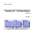
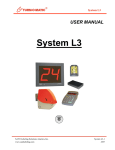
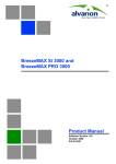
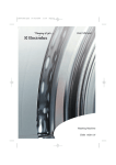
작성일자 2008-3-24 개정일자 2008-3-24 개정번호 Rev.(0) Service Manual (Model : IS-971 / 971R / 971RF) INDEX 2. Disassembly 1. Service & Inspection 2-1. Disassembly 1-1. Temperature 2-1-1. Frame Cover Disassembly - Temp doesn’t increase - Temp doesn’t decrease - Temp trembling - Variation Cause 2-1-2. Shaking table Disassembly 2-1-3. Main board PCB Disassembly 2-1-4. SSR Disassembly - Temp keeps rising 2-1-5. Relay Disassembly 1-2. Power 2-1-6. Noise Filter Disassembly - No Power - Power shut off during operation - Power shut off after turning on 2-1-7. Fan Cover Disassembly 2-1-8. Heater Disassembly 2-1-9. Motor / Fan Disassembly 2-1-10. Display PCB Disassembly 1-3. DISPLAY 2-1-11. Temperature control Sensor Disassembly - Push button error - Display error 2-1-12. High Temp Limit Sensor Disassembly 1-4. Door 2-1-13. Door Disassembly - Door can’t close 2-1-14. Fuse Disassembly 2-1-15. Communication Board Disassembly 1-5. Noise - Noise while operating the chamber. - Noise when SHAKING 2-1-16. Compressor unit Disassembly 2-1-17. Transformer Disassembly 1-6. Leakage 2-1-18. Vibrating Frame Assembly Disassembly - Breaker actives 2-1-19. Belt Disassembly 1-7. RS communication 2-1-20. Shaking Motor Disassembly - No connection 2-1-21 Rotation Pin Set Disassembly 1-8. SHAKING - SHAKING Error - SHAKING stops with ERR - 2 - 2-2. Inspection 2-2-1. Main Board Relay output Power inspection 2-2-2. Main Board Heater output Power inspection 2-2-3. Transformer AC output Power inspection 2-2-4. Heater short circuit inspection 2-2-5. Heater leakage inspection 2-2-6. Motor leakage inspection 2-2-7. Noise Filter error inspection 2-2-8. Main Power Switch error inspection 2-2-9. SSR error inspection 2-2-10. Wire snaps inspection 2-2-11. Connect service valve and examine pressure of refrigerant 2-2-12. How to recharge refrigerant 2-2-13. Current leakage of compressor - 3 - 1. Service 1-1. Temperature Classification Temperature Symptom Service Factor Temp doesn’t increase Heater malfunction 1. After setting the Max temp and then press Start Button to operate the unit. 2. Check the Heater temp itself. (Be careful heater is very hot.) Check point 3. Measure resistance checking positive terminal of heater using of the multi meter. Æ If resistance doesn’t measure, it is a malfunction - Replace a heater. Solution 1. “2-1-7. Fan Cover disassembly” Reference 2. “2-1-8. Heater disassembly” Reference 3. Assembly is in reverse disassembly. (Heater should be checked resistance for inferiority.) Classification Temperature Symptom Service Factor Temp doesn’t increase Relay Malfunction 1. Press the Start Button to operate the unit, Measure Voltage of Output terminal using of the multi meter. Æ If Voltage doesn’t measure, it is a malfunction Check point - 4 - - Replace the Relay. Solution 1. “2-1-1. Frame Cover disassembly” Reference 2. “2-1-5. Relay disassembly” Reference 3. Assembly is in reverse disassembly. Classification Temperature Symptom Service Factor Temp doesn’t increase SSR Malfunction 1. Set the SV value higher than PV, Press the Start Button. 2. Check the HEAT LED is lightning on Display. (No Flickering, Lightning) 3. Check Terminal Resistance using of the Multi meter. (Resistance MODE) Check point Æ If resistance doesn’t measure, it is a malfunction. - Replace the SSR. Solution 1. “2-1-1. Frame Cover disassembly” Reference 2. “2-1-4. SSR disassembly” Reference 3. Assembly is in reverse disassembly. - 5 - Classification Temperature Symptom Temp doesn’t increase Service Factor PCB Malfunction 1. Set the SV value higher than PV, Press the Start Button. 2. Check the HEAT LED is lightning on Display. (No Flickering, Lightning) 3. Check Terminal Resistance using of the Multi meter. (DC MODE) Check point Æ If resistance doesn’t measure, it is a malfunction. - Replace the PCB. Solution 1. “2-1-1. Frame Cover disassembly” Reference 2. “2-1-3. Main board PCB disassembly” Reference 3. Assembly is in reverse disassembly. - 6 - Classification Temperature Symptom Service Factor Temp doesn’t increase Wire from heating parts disconnection 1. Check the wire from Heater to SSR. 2. “ Wire disconnection Inspection” Reference Æ If resistance is not measured, it is disconnection. Check point 3. Check the end terminal connection of the wire. Æ If connection is not good, it is disconnection. - If it is disconnection, replace the wire. Solution 1. “2-1-1. Frame Cover disassembly” Reference 2. Replace the wire. 3. Assembly is in reverse disassembly. - 7 - Classification Temperature Symptom Service Factor Temp doesn’t increase Refrigerant shortage 1. Set the Ambient temp 25°C to operate. Set the SV: 15℃ and then wait for temp stabilization over 30minutes after reaching SV. 2. Measure Refrigerant capacity. Check point 3. Normal range(Room temp : 25℃, Chamber temp : 15℃) - 1.9 ~ 2.1 Bar (28 ~ 32 Psi) ※ “2-2-11.Service valve connection or Refrigerant pressure inspection” Reference - Fill up Refrigerant gas Solution 1. “2-1-1. Frame Cover disassembly” Reference 2. “2-2-12. How to fill up Refrigerant gas” Reference 3. Assembly is in reverse disassembly. Classification Temperature Symptom Service Factor Temp doesn’t increase Refrigeration System Malfunction 1. The unit operates. Check point 2. Check whether the refrigeration System is noisy or not. Æ If it’s noisy, the refrigeration System is malfunction. 3. Check the refrigeration voltage and current leakage. - Replace the refrigeration System. 1. “2-1-7. Fan Cover disassembly” Reference Solution 2. “2-1-16. Refrigeration System back panel disassembly” Reference 3. Assembly is in reverse disassembly. - 8 - Classification Temperature Check point Symptom Service Factor Temp doesn’t increase Refrigeration System Overload 1. Check the temp of Refrigeration head. 2. Over 95°C, Refrigeration part Overload - Cool down the Refrigeration system. 1. “2-1-7. Fan Cover disassembly” Reference Solution 2. Waiting for the refrigeration System is cool or Make the Refrigeration temp is down using of compressed Air. 3. After operating the unit and then check the problems. 4. Assembly is in reverse disassembly. Classification Temperature Symptom Service Factor Temp doesn’t decrease Refrigeration line (Filter, Dryer, Capillary tube)Chock 1. Operates the unit. Check point 2. The low pressure (Refrigerant gas) indicates vacuum pressure. Æ Dryer chock. Solution - Replace the Dryer Classification Temperature Symptom Service Factor Temp doesn’t decrease Refrigeration fan motor malfunction 1. Operates the unit. Check point 2. Check whether the refrigeration part works. 3. If the refrigeration part works, Check the input voltage of Fan motor using of the multi meter. 4. If the pressure is normal, the fan motor is malfunction. Solution - Replace the fan motor. 1. “2-1-7. Fan Cover disassembly” Reference - 9 - 2. “2-1-9. Motor / Fan disassembly” Reference 3. Assembly is in reverse disassembly. Classification Symptom Temperature Temp doesn’t decrease Check point 1. Check dust on the condenser. Service Factor Condenser dust contamination -Clean up the condenser. Solution 1. Remove the Condenser cover panel on the bottom of the unit. 2. Clean dust on the condenser. 3. Assembly is in reverse disassembly. Classification Temperature Symptom Service Factor Temp doesn’t decrease Disconnection of a Refrigeration wire or terminal 1. Operates the unit. Check point 2. Check the refrigeration works. 3. Check a disconnection of terminal or Wire from the refrigeration M/C to the refrigeration part. - Check the wire. 1. “2-1-1. Frame Cover disassembly” Reference Solution 2. Change a wire in case of wire disconnection. 3. Change a terminal in case of terminal disconnection. 4. Assembly is in reverse disassembly. - 10 - Classification Temperature Symptom Service Factor Temp trembling Wrong PID Value 1. Press Temp button with turning on the Main power switch at the same time. Check point 2. Press Auto tuning Button to check the PID value. Æ If the unit PID value is different from a basis PID value, It’s error. - Operate the Auto tuning. 1. Press Temp button to set the desired temp. Solution 2. Press A/T button for a second, Auto Tune displayed on the temp display and A/T LED ON. 3. After pressing Start Button, RUN LED is ON. A/T LED flickers and then operates the Auto Tune. 4. Finishing Auto Tune, LED is off. The temp by Auto Tune keeps controlling temperature. Classification Temperature Check point Symptom Service Factor Temp trembling PCB Malfunction 1. - Operate the Auto tuning. Æ, If the temp is trembling after Auto tuning, It is PCB Malfunction - Replace the PCB. Solution 1. “2-1-1. Frame Cover disassembly” Reference 2. “2-1-3. Main board PCB disassembly” Reference 3. Assembly is in reverse disassembly. - 11 - Classification Temperature Symptom Service Factor Temp trembling Temp Sensor connection inferiority 1. Check the temp sensor terminal bolts of PCB. Æ If bolts are loosen, it cause disconnection inferiority. Check point - Tighten the temp sensor terminal bolts of PCB. Solution 1. “2-1-1. Frame Cover disassembly” Reference 2. Tighten the temp sensor terminal bolts of PCB. 3. The assembly is reverse order of disjointing. Classification Temperature Symptom Service Factor Temp trembling Refrigeration malfunction, Endothermic value fluctuation 1. Operates the unit. Check point 2. Set the temp 25°C and keep the temp. 3. Check the low pressure of refrigeration, when the temp trembles. If the low pressure of refrigeration trembles together, the refrigeration part is malfunction. Solution 1. Check the refrigeration system parts.. Check Refrigerant shortage / Refrigerant overcharge / Ambient temp / Condenser dust - 12 - Classification Temperature Check point Symptom Service Factor Variation Cause PCB Malfunction 1. Replace the PCB to check the situation. Æ If Variation is not caused, it is PCB Malfunction. - Replace the PCB. Solution 1. “2-1-1. Frame Cover disassembly” Reference 2. “2-1-3. Main board PCB disassembly” Reference 3. The assembly is reverse order of disjointing. Classification Temperature Check point Symptom Service Factor Variation Cause BIAS Value modification 1. Measure temp of the inner chamber using of A exterior temp detector installed in the middle. Æ If displayed temp and the temp detector value are different, Modify BIAS Value.. - BIAS Value Modification 1. Install A exterior temp detector verified inner chamber. 2. After setting the temp value, Wait for the temp that is stabilized.(About 2hours over) Solution 3. Measure the temp detector installed inner chamber. 4. Press Temp Button six times to modify the Bias value. 5. Modify the BIAS value to set the temp is equal to the temp detector. And then press the ENTER Button to restore the value. 6. Modify the temp value. - 13 - Classification Temperature Check point Symptom Service Factor Variation Cause Measurement Inferiority 1. Check the temp detector position. Æ If the temp detector is not in the middle position, It’s a malfunction. - Measuring position change. Solution 1. The sensor of temp detector positioned in the middle of inner chamber. 2. Fixture and the sensor of temp detector should be intervals minimum 15mm. (Standard Test Guide Reference) Classification Temperature Symptom Service Factor Variation Cause Temp Sensor connection inferiority 1. Check the temp sensor terminal bolts of PCB. Æ If bolts are loosen, it cause disconnection inferiority. Check point - Tighten the temp sensor terminal bolts of PCB. Solution 1. “2-1-1. Frame Cover disassembly” Reference 2. Tighten the temp sensor terminal bolts of PCB. 3. The assembly is reverse order of disjointing. - 14 - Classification Temperature Check point Symptom Service Factor Temp keeps rising PCB Malfunction 1. Replace the PCB to check the symptom. Æ If Variation is not caused, it is PCB Malfunction. - Replace the PCB. Solution 1. “2-1-1. Frame Cover disassembly” Reference 2. “2-1-3. Main board PCB disassembly” Reference 3. The assembly is reverse order of disjointing. Classification Temperature Symptom Service Factor Temp keeps rising SSR Malfunction 1. Separate the Input SSR of Harness. 2. Measure resistance checking SSR output using of the multi meter. (Resistance MODE) Æ If resistance measure, it is SSR malfunction. Check point - Replace the SSR. Solution 1. “2-1-1. Frame Cover disassembly” Reference 2. “2-1-4. SSR disassembly” Reference 3. The assembly is reverse order of disjointing. - 15 - 1-2. Power Classification Power Check point Symptom Service Factor No Power Fuse disconnection 1. Check the Fuse using of the multi meter. Æ If Resistance is not measured, Fuse disconnection. - Replace the Fuse. Solution 1. “2-1-14. Fuse disassembly” Reference 2. The assembly is reverse order of disjointing. Classification Power Symptom Service Factor No Power Switch Malfunction 1. Measure output terminals No.2,5 When turning on the Main power. Æ If Power is not measured, Switch Malfunction. Check point - Replace the Switch. 1. “2-1-10. Display PCB disassembly” Reference Solution 2. Separate Switch wiring. (When assembling, location is a caution.) 3. Pull out the parts which are involved in the Switch upper & bottom from the panel. 4. The assembly is reverse order of disjointing. - 16 - Classification Power Symptom Service Factor No Power PCB Malfunction 1. Check Voltage from output terminal of AC in PCB. Æ If Voltage is measured without Power, PCB Malfunction. Check point -Power* Blue: 35V * Red:13.7V - Replace the PCB. Solution 1. “2-1-1. Frame Cover disassembly” Reference 2. “2-1-3. Main board PCB disassembly” Reference 3. The assembly is reverse order of disjointing. Classification Power Symptom Service Factor No Power Trans Malfunction 1. Check Voltage from output terminal of AC in PCB. Æ If Voltage is measured without Power, PCB Malfunction. Check point -Power* Blue: 35V * Red:13.7V Solution - Replace the Trans. - 17 - 1. “2-1-1. Frame Cover disassembly” Reference 2. “2-1-17. Trans disassembly” Reference 3. The assembly is reverse order of disjointing. Classification Power Check point Solution Symptom No Power Check point Laboratory power Malfunction 1. Check the electricity of socket with multi meter. Æ If power doesn’t measure or value is lower or higher, Laboratory power Malfunction. -Make Power of Laboratory stabilization. Classification Power Service Factor Symptom Service Factor No Power Power code line disconnection inferiority 1. Check between Fuse holder and Soldering part of power code line. Æ If Soldering part is separated, disconnection inferiority - Sold again. Solution 1. “2-1-1. Frame Cover disassembly” Reference 2.. After soldering between Main cord and fuse holder, Tube it with Shirking tube. 3. The assembly is reverse order of disjointing. - 18 - Classification Power Symptom Service Factor No power Short circuit of power or disconnection 1. “2-2-10 Wiring short circuit Inspection” Reference Check point Æ If resistance is not measured, it is short circuit. 2. Check the end terminal of wire. Æ If wire connection is not good, disconnection Malfunction. - Check the wire. 1. “2-1-1. Frame Cover disassembly” Reference Solution 2. If it’s short circuit, replace the wire. 3. If it’s disconnection, reassemble the terminal. 4. The assembly is reverse order of disjointing. - 19 - Classification Power Symptom Power shut off during operation Service Factor PCB Malfunction 1. Turn on the Main power Switch. 2. Set the SV value 100°C, Press the Start Button to operate. 3. Check DC Voltage from heater output terminal in PCB. Æ If Voltage is not measured, PCB Malfunction. 4. Check DC Voltage from Relay output terminal in PCB. Æ If Voltage is not measured, PCB Malfunction. Check point 5. Check DC Voltage from Refrigeration system output - Heater - terminal in PCB. Æ If Voltage is not measured, PCB Malfunction. - Compressor - Replace the PCB. Solution 1. “2-1-1. Frame Cover disassembly” Reference 2. “2-1-3. Main board PCB disassembly” Reference 3. The assembly is reverse order of disjointing. - 20 - - Relay - Classification Power Symptom Service Factor Power shut off during operation Over current 1. Check the fuse and then replace it. 2. Check an electric current both ground terminal and Wire using of the multi meter. (Check the polar terminal of Wiring) Check point 3. Check Heater leakage. Æ 1. If fuse is down, replace it. If heater is not leakage and 2. If current Ground terminal and wire doesn’t apply current during measurement, It’s Over current. Solution Classification Power - Over current is possible, but check shot circuit for all wires and electric parts. Symptom Service Factor Power shut off during operation. Electric capacity over in Multi outlet 1. Check an electric outlet capacity connected the unit. Check point 2. Check total units connected the multi electric outlet. Æ If total units connected the multi electric outlet is over than the outlet capacity, multi electric outlet malfunction. Solution - Use the multi electric outlet under capacity. - 21 - Classification Power Symptom Service Factor Power shut off after turning on Heater leakage 1. Check the fuse. 2. Separate the heater terminal and wire. 3. Measure Resistance both the heater terminal and heater exterior. Æ If fuse is down and heater resistance is measured, Heater leakage. Check point - Replace the heater. Solution 1. “2-1-7. Fan Cover disassembly” Reference 2. “2-1-8. Heater disassembly” Reference 3. The assembly is reverse order of disjointing. (Heater should be checked resistance for inferiority.) - 22 - Classification Power Symptom Service Factor Power shut off after turning on Motor leakage 1. Check the fuse. 2. Separate the motor wires. 3. Measure Resistance both the motor wire and motor exterior. Check point Æ If motor resistance is measured, Motor leakage. - Replace the motor. Solution 1. “2-1-7. Fan Cover disassembly” Reference 2. “2-1-9. Motor / Fan disassembly” Reference 3. The assembly is reverse order of disjointing. Classification Power Symptom Service Factor Power shut off after turning on Refrigeration System Leakage 1. Separate the Refrigeration System wires. 2. Measure Resistance for two terminals each in three times using of the multi meter. Æ If Resistance is measured in three cases, Refrigeration System Leakage. Check point - 23 - - Replace the Refrigeration System 1. “2-1-7. Fan Cover disassembly” Reference Solution 2. “2-1-16. . Refrigeration Unit disassembly” Reference 3. The assembly is reverse order of disjointing. Classification Power Symptom Service Factor Power shut off during operation. Wiring insulation malfunction 1. Check the fuse. Check point 2. If fuse is down, replace it.. 3. Check Resistance both ground wire and Main plug using of the multi meter. Æ If resistance is measured, it is short circuit. Solution - Replace the wire. (“Wiring short circuit Inspection” Reference) Classification Power Symptom Service Factor Power shut off after turning on Electric capacity over in Multi outlet 1. Check the fuse. Check point 2. Check an electric outlet capacity connected the unit. 3. Check total units connected the multi electric outlet. Æ If total units connected the multi electric outlet is over than the outlet capacity, multi electric outlet malfunction. Solution - Use the multi electric outlet under capacity. - 24 - 1-3. DISPLAY Classification Display Check point Symptom Service Factor Push button error DISPLAY PCB error 1. Disconnect Display board from the panel, test pushing all buttons one by one Æ If you don’t detect any reaction from button, the Display board is out of order - Replace the Display board Solution 1. Refer to “2-1-10. Display board disassembly” 2. The assembly is reverse order of disjointinging. Classification Display Symptom Service Factor Push button error DISPLAY PCB assembly error 1. DISPLAY PCB의 고정 상태를 확인한다. Check point 2. DISPLAY PCB를 판넬에서 분리하여 모든 버튼을 직접 눌러 본다. Æ DISPLAY PCB의 고정이 유격이 있고, 분리하여 버튼을 직접 눌렀을 때 정상 작동을 하면 조립 상태 불량 - Replace Display board Solution 1. Refer to “2-1-10. Display board disassembly” 2. The assembly is reverse order of disjointinging. Classification Display Check point Symptom Service Factor Display error DISPLAY PCB error 1. Disassemble the Harness on the Display board, and re-assemble correctly. Æ If you still notice display error, the Display board is out of order - Replace DISPLAY PCB. Solution 1. Refer to “2-1-10. Display PCB disassembly” 2. The assembly is reverse order of disjointinging. - 25 - Classification Display Symptom Service Factor Display error Main PCB error 1. Disassemble the Harness on the Display board, and re-assemble correctly. Check point 2. Replace Panel on Display board Æ If you still notice display error, the Main control board is out of order Replace a new PCB. Solution 1. “2-1-1. Frame Cover disassembly” Reference 2. “2-1-3. Main board PCB disassembly” Reference 3. The assembly is reverse order of disjointing. Classification Display Check point Symptom Service Factor Display error Temp. Sensor error 1. Replace a new Temp. Sensor. Æ If display is OK, the previous Sensor is out of order - Replace a new Temp. Sensor 1. “2-1-1. Frame Cover disassembly” Reference Solution 2. “2-1-7. Fan Cover disassembly” Reference 3. “2-1-11. Temperature control Sensor disassembly” Reference 5. The assembly is reverse order of disjointing. - 26 - Classification Display Symptom Service Factor Display error Temp sensor contact error 1. Check the bolts of Temp. Sensor on the Main control board. Æ If you detect bolting is loose, contact error Check point - Fasten the blots of Temp. Sensor on the Main control board. Solution 1. “2-1-1. Frame Cover disassembly” Reference 2. Fasten the blots of Temp. Sensor on the Main control board. 3. The assembly is reverse order of disjointing. - 27 - Classification Display Symptom Service Factor Display error Harness contact error 1. Disassemble the Harness on the Display board, and re-assemble correctly. Æ If Display turns OK, Harness contact was error Check point - Replace Display board Solution 1. Refer to “2-1-10. Display PCB disassembly” 2. Disassemble the Harness on the Display board, and re-assemble correctly. 3. Assembly is reverse order of disjointing. - 28 - 1-4. Door Classification Door Symptom Service Factor Not fixed Gas spring 1. When opening the door completely, the door should not be closed by Gas spring. Check point - Replace the Gas spring. Solution 1. “2-1-13. Door disassembly” Reference 2. The assembly is reverse order of disjointing. Classification Door Symptom Service Factor Not fixed Door hinge damage 1. Check the spring of hinge. Check point Æ If spring is separated, It’s a malfunction. - Replace the door hinge Solution 1. “2-1-13. Door disassembly” Reference 2. Assembly is in reverse disassembly. - 29 - 1-5. Noise Classification Noise Check point Symptom Service Factor Noise while operation the unit Motor error 1. Check if Fan is interfered by something Æ If there is nothing to interfere Fan, Motor is out of order - Replace a new Fan. Solution 1. “2-1-7. Fan Cover disassembly” Reference 2. “2-1-9. Motor / Fan disassembly” Reference 3. The assembly is reverse order of disjointing. Classification Noise Check point Symptom Service Factor Noise while operation the unit Compressor error 1. Check if there is mechanical crushing noise on the compressor Æ If there is noise, the compressor is out of order - Replace compressor 1. “2-1-1. Frame Cover disassembly” Reference Solution 2. “2-1-16. Compressor unit disassembly” Reference 3. The assembly is reverse order of disjointing. - 30 - Classification Noise Symptom Service Factor Noise while operation the unit Noise from overloaded compressor 1. Check if there is mechanical crushing noise on the compressor Æ If there is noise, the refrigerant is too much filled 1) Set room temp on around 25℃, set SV on 15℃.wait 30mins to be stable running Check point 2) Measure the refrigerant. 3) Proper range(Room temp : 25℃, SV : 15℃) - 1.9 ~ 2.1 Bar (28 ~ 32 Psi) ※ Refer to “2-2-11.Service valve connection and refrigerant pressure" - Release the overloaded refrigerant 1. “2-1-1. Frame Cover disassembly” Reference Solution 2. “2-2-11. .Service valve connection and refrigerant pressure” reference 3. “2-2-12. Filling refrigerant” reference. 4. The assembly is reverse order of disjointing. Classification Noise Check point Symptom Service Factor Noise while operation the unit Loosen compressor holding nuts 1. Check the noise is coming from compressor itself or not. 2. Check the holding nuts are loose. - - If they are loose, tighten them by using spanner. Solution 1. “2-1-1. Frame Cover disassembly” Reference 2. The assembly is reverse order of disjointing. - 31 - Classification Noise Check point Symptom Service Factor Noise while operation the unit Noise from Fan interference 1. Open Bottom panel of the Chamber and check. Æ Check Fan interference - Reassemble the unit.. 1. “2-1-7. Fan Cover disassembly” Reference Solution 2. “2-1-9. Motor / Fan disassembly” Reference 3. If the Fan is not damaged, re-assemble the fan. 4. The assembly is reverse order of disjointing. Classification Noise Symptom Service Factor Noise while SHAKING Motor error 1. If the motor generate noise, the motor is error Check point - Replace the motor with a new one 1. “2-1-2. Shaking table disassembly” Reference Solution 2. “2-1-18. Vibrating Frame Assembly disassembly” Reference 3. “2-1-20. Shaking Motor disassembly” Reference 4. The assembly is reverse order of disjointing. - 32 - Classification Noise Symptom Service Factor Noise while SHAKING Noise coming from plate touching 1. Check if the noise is coming from plate touching while Shaking. Check point Æ Plate is error - Replace Plate .. Solution 1. “2-1-2. Shaking table disassembly” Reference 2. “2-1-18. Vibrating Frame Assembly disassembly” Reference 3. The assembly is reverse order of disjointing. Classification Noise Check point Symptom Service Factor Noise while SHAKING Bearing error 1.Chekc if the bearing has gap by turning Rotation Pin Set Æ If the bearing has gap, the bearing is error - Replace Rotation Pin Set. 1. “2-1-2. Shaking table disassembly” Reference Solution 2. “2-1-18. Vibrating Frame Assembly disassembly” Reference 3. “2-1-21 Rotation Pin Set disassembly” Reference 4. The assembly is reverse order of disjointing. - 33 - 1-6. Current leakage Classification Leakage Symptom Service Factor Circuit breaker activates Heater Step 1. Check out fuses. => If fuses are out of order, current leakage happens. Step 2. Taking out wiring of heater. Then, measure resistance between terminal and surface of heater with resistance meter. => If resistance measures, current leakage happens. Check point - Replace a new heater. Solution 1. “2-1-7. Fan Cover disassembly” Reference 2. “2-1-8. Heater disassembly” Reference 3. The assembly is reverse order of disjointing.(Check heater resistance before assembly) - 34 - Classification Leakage Symptom Service Factor Circuit breaker activates Motor Step 1 . Check out fuses. Step 2. Taking out motor wiring. Step 3. Check out resistance between motor wire and surface of motor with resistance meter. Æ If fuses are out of order or resistance measures, current leakage happens. Check point - Replace a new motor. 1. “2-1-14. Fuse disassembly” Reference Solution 2. “2-1-7. Fan Cover disassembly” Reference 3. “2-1-9. Motor / Fan disassembly” Reference 4. The assembly is reverse order of disjointing. - 35 - Classification Leakage Symptom Service Factor Circuit breaker activates Compressor Step 1. Taking out wiring of compressor. Step 2. Measure 3 different resistance of 3 wires between 2 ends. Æ If all 3 different resistance are measured, current leakage happens. Check point - Replace compressor 1. “2-1-1. Frame Cover disassembly” Reference Solution 2. “2-1-16. Compressor unit disassembly” Reference 3. The assembly is reverse order of disjointing. Classification Leakage Symptom Service Factor circuit breaker activates Insulation of wire Step 1. Check out fuses. Check point Step 2. Replace fuses if it is out of order. Step 3. Measure resistance between main plug and earth resistance meter. Æ If resistance measures, insulation of wire is out of order. Solution - Replace wires ( Refer to “wire snap examination”) - 36 - 1-7. RS Communication Classification Communication Symptom Service Factor No connection Communication PCB 1. Check out connection of wires of Communication PCB. 2. Replace communication PCB. Check point Æ If it works after replacement, communication PCB is out of order. - Replace communication. Solution 1. “2-1-10. Display PCB disassembly” Reference 2. “2-1-15. Communication Board disassembly” Reference 3. The assembly is reverse order of disjointing. - 37 - 1-8. SHAKING Classification SHAKING Symptom Service Factor SHAKING error Main PCB error 1.Replace a new Main Board PCB Check point Æ If the unit works OK, PCB was error - Replace PCB. Solution 1. “2-1-1. Frame Cover disassembly” Reference 2. “2-1-3. Main board PCB disassembly” Reference 3. The assembly is reverse order of disjointing. Classification SHAKING Symptom Service Factor SHAKING error Motor error 1. If the motor generate noise, the motor is error Check point - Replace shaking motor 1. “2-1-2. Shaking table disassembly” Reference Solution 2. “2-1-18. Vibrating Frame Assembly disassembly” Reference 3. “2-1-20. Shaking Motor disassembly” Reference 4. The assembly is reverse order of disjointing. - 38 - Classification SHAKING Symptom Service Factor SHAKING error PAN SPRING error 1. Check PAN SPRING is broken. Check point - Replace Pan Spring. 1. “2-1-2. Shaking table disassembly” Reference Solution 2. “2-1-18. Vibrating Frame Assembly disassembly” Reference 3. Replace Pan Spring. 4. The assembly is reverse order of disjointing. Classification SHAKING Symptom Service Factor SHAKING error VIBRATING FRAME damaged 1. Check VIBRATING FRAME has been damaged. Check point -Replace a new VIBRATING FRAME. Solution 1. “2-1-2. Shaking table disassembly” Reference 2. “2-1-18. Vibrating Frame Assembly disassembly” Reference 3. The assembly is reverse order of disjointing. - 39 - Classification SHAKING Symptom Service Factor SHAKING error Harness contact error 1. Check Harness contact Check point - Re-assemble Harness. Solution 1. “2-1-2. Shaking table disassembly” Reference 2. “2-1-18. Vibrating Frame Assembly disassembly” Reference (Check harness after removing Shaking cover) 3. The assembly is reverse order of disjointing Classification SHAKING Symptom Service Factor SHAKING error Belt got loosen or out of way 1. Check the motor works well. Check point 2. Check Vibrating Frame works well. Æ If Motor is OK, but Vibrating Frame is not working-> Belt got loosen or out of way - Replace belt 1. “2-1-2. Shaking table disassembly” Reference Solution 2. “2-1-18. Vibrating Frame Assembly disassembly” Reference 3. “2-1-19. Belt disassembly” Reference 4. The assembly is reverse order of disjointing - 40 - Classification SHAKING Symptom Service Factor The unit suddenly stops with error while SHAKING Motor error 1. Check the Motor works well. Check point Æ If not, the motor is error - Replace a new morot. 1. “2-1-2. Shaking table disassembly” Reference Solution 2. “2-1-18. Vibrating Frame Assembly disassembly” Reference 3. “2-1-20. Shaking Motor disassembly” Reference 4. The assembly is reverse order of disjointing. Classification SHAKING Symptom Service Factor The unit suddenly stops with error while SHAKING Harness contact error 1. Check if the display shows an error message “ERR. C” Check point 2. Check the Motor works well. Æ If the display shows “ERR. C” or the Motor does not work-> Harness contact error - Re-assemble Harness. Solution 1. “2-1-2. Shaking table disassembly” Reference 2. “2-1-18. Vibrating Frame Assembly disassembly” Reference (Check harness after removing the rear cover.) 3. The assembly is reverse order of disjointing. - 41 - 2. Disassembly & Inspection 2-1. Disassembly 2-1-1. Frame Cover Disassembly Loosen displayed bolts using of “+” Driver Separate the back Disassembly Completion. side panel. - 42 - 2-1-2. Shaking table Disassembly Loosen bolts 4mm hexagon Wrench, Remove Washer. Disassembly completion. - 43 - 2-1-3. Main board PCB Disassembly Displayed part is a Main board PCB. (yellow circle) After removing electric wires, Loosen the displayed bolts to disassembly. (yellow circle) - 44 - 2-1-4. SSR Disassembly Displayed part is a SSR. (yellow circle) After removing electric wires, Loosen the displayed bolts to disassembly. (yellow circle) 2-1-5. Relay Disassembly Displayed part is a Relay. (yellow circle) After removing electric wires, Loosen the displayed bolts to disassembly. (yellow circle) - 45 - 2-1-6. Noise Filter Disassembly Displayed part is a Noise Filter. (yellow circle) After removing electric wires, Loosen the displayed bolts to disassembly. (yellow circle) - 46 - 2-1-7. Back side panel Disassembly Loosen the displayed fixed bolts.(Red circle) Loosen the displayed fixed bolts. (Red circle) - 47 - Fan Cover Disassembly completion. 2-1-8. Heater Disassembly Loosen fixing bolts on the circled, to disconnect Heater Ass’y. After disconnecting wires on the heater pull out to the rear direction. - 48 - Heater Disassembly done 2-1-9. Motor / Fan Disassembly There is fixing bolts on the arrorw Loosen the bolts on the circle. Loosen the bolts on the circle to remove fixing panel and High Temp Limit Sensor. Pull up to disassemble - 49 - 2-1-10. Display PCB Disassembly Loosen the bolts on the circle. Remove panel Disassembly done 2-1-11. Temperature control Sensor Disassembly The circled is Temperature control Sensor. Loosen the circled bolts. - 50 - Disassembly done. 2-1-12. High Temp Limit Sensor Disassembly The circled is High Temp Limit Sensor. Loosen the circled bolts. Loosen the circled bolts. Loosen the circled bolts to disconnect. - 51 - 2-1-13. Door Disassembly Loosen the circled bolts to disconnect gas spring. Assembly order on gas spring.(TOP) Assembly order on gas spring.(bottom) Remove gas spring and close door. You can find door hinge on the rear Put “-“ driver on the hinge. - 52 - Turn “-” driver to the arrow direction to disconnect Loosen bolts. hinge cover. - 53 - 2-1-14. Fuse Disassembly Push and turn left with “-” driver to remove fuse. 2-1-15. Communication Board Disassembly Loosen the circled bolts. Disconnect panel Loosen the circled bolt to remover Communication board. - 54 - 2-1-16. Compressor unit Disassembly Dryer Solenoid Valve Compressor Fan Motor This shows compressor units. - 55 - Condenser 2-1-17. Transformer Disassembly The circled shows a transformer. Disconnect all wires and loosen the circled blots to remove. - 56 - 2-1-18. Vibrating Frame Assembly Disassembly Loosen the circled bolts to remove Shaking cover. Loosen the circled by using 8mm Spanner, 4mm Loosen the circled bolts (same procedure with Loosen the circled by using 8mm Spanner, 4mm SI Disassembly) Wrench. Loosen the circled by using 4mm Wrench. Vibrating Frame Assembly can be removed as Wrench. shown. - 57 - 2-1-19. Belt Disassembly (Refer to SI Disassembly) Rotate Driving wheel system when lift up belt. Hold belt and lift it up. Assemble : 1. Place belt at the motor. 2. Place a part of belt at the driving wheel system and rotate it. - 58 - 2-1-20. Shaking Motor Disassembly Loose no head screw with 2mm wrenc Take out pulley of motor. Loose screws(yellow circle) with 4mm h. Separate harness of motor. wrench. Separate motor and motor bracket out of Separation done. the body. - 59 - Loose screws with 4mm wrench. 2-1-21 Rotation Pin Set Disassembly Head of wrench screw through hole Loose screw with 4 m m w r e n c h by can be seen when you rotate rotation rotating rotation Pin Set. pin set. - 60 - Separation done. 2-2. Inspection 2-2-1. Output voltage of Relay on Main Control Board 1. Press “START” key to operate unit. 2. Measure output voltage of terminal with voltage meter (DC MODE) - 61 - 2-2-2. Output voltage of Heater Main Control Board 1. Set temperature above PV(actual value) and press “START” key. 2. Check out HEAT LED on display. (It should be ON.) 3. Measure output voltage of terminal with voltage meter. (DC MODE) - 62 - 2-2-3. AC output power of Transformer 1. Switch ON. 1. Switch ON. 2. Measure output power(blue wires, 35V) with voltage meter (AC mode) 2. Measure output power (red wires, 13.7V)l with voltage meter(AC mode) - 63 - 2-2-4. Short-circuit of Heater Measure two heater contact by using TESTER(resistance MODE) - 64 - 2-2-5. Heater leakage Measure resistance(resistance MODE) between Heater and heater body - 65 - 2-2-6. Motor leakage check Measure resistance between motor and terminal of input power. - 66 - 2-2-7. Noise Filter defect 1. Switch ON. 2. Measure output voltage with voltage meter.(AC MODE) - 67 - 2-2-8. Main Power Switch defect 1. Switch ON. 2. Measure output voltage with voltage meter(AC MODE). - 68 - 2-2-9. SSR Board defect 1. Take out harness of SSR input. 2. Measure resistance of SSR output with resistance meter. - 69 - 2-2-10. Wire snap 1. Resistance meter. 1. Switch ON. Measure between plug and Input Measure between plug and output 2. Measure resistance between 2. Measure output between plug of Noise filter. of Noise Filter. plug and fuse holder. Measure between plug and Relay. and main power switch. Measure between plug and input voltage (AC) of Main Board PC B. - 70 - -2-11. Connect service valve and examine pressure of refrigerant Low Pressure High Pressure Main Nut Gauge Nut Prepare Manifold Gauge and close low Read instruction carefully. Loose 14mm “Gauge Nut” and 20mm connect at low pressure of manifold pressure, high pressure, and line. (Note : Must be acknowledged.) “Main Nut” gauge. (2) Ball (nut-17mm) (1) Main (nut-20mm) (wrench handle-4m ) (3) Gauge (nut-14mm) Open 4mm wrench screw. Internal pressure indicates at manifold * Clockwise : Close gause. Service valve * Anti-clockwise : Open - 71 - 2-1-12. How to recharge refrigerant Note) Environmental temperature is nearly 25 to 30C. 1. Connect low pressure hose to service valve. 2. Set temperature at 25℃ and run unit. 3. Pressure indicator drops to low pressure immediately once compressor runs. 4. When temperature reaches 25℃ and wait until temperature stabilization for around 30minutes. 1. Check out pressure of Manifold Gauge. - Normal : (Ambient : 25~30℃, Bath temp : 25℃) SI-300R/600R : 2.0kg/cm² / 28.4psi SI-971R/971RF : 1.5kg/cm² / 21.3psi In case High pressure ( overcharge) Open low pressure valve of manifold gauge and pressure indicator drops slowly with extract sound. Note : When you open low pressure valve of manifold gauge, open about 5 sec only and close quickly and wait for stabilization (2~3nunites.) Try above action several times until pressure indicator reaches proper value. Incase pressure indicator is high – Extract refrigerant because the symptom is due to overcharge. Separate hose of manifold gauge for refrigerant suction. - Middle of 3 hoses. - 72 - Incase low pressure (lack of refrigerant) Incase pressure indicator is low – Refrigerant should be recharged due to lack of refrigerant. Separate hose of manifold gauge for refrigerant suction. - Middle of 3 hoses. 9 Connect line (blue circle) to refrigerant 9. Open valve of tank ( blue circle.) to tank. anti-clockwise. 9 Refrigerant will be filled with in valve of manifold gauge, open the hose but air and refrigerant about 5 sec only and close is mixed in the hose. 9 When you open low pressure quickly Open valve(blue circle at the and wait for stabilization (2~3nunites.) left picture) for short time to 9 extracgt mixed air and close it. Open refrigerant low pressure goes to valve compressor. Pressure indicator increases. - 73 - and Try above action several times until pressure reaches proper value. indicator Close valve of refrigerant tank after recharge refrigerant. Separate refrigerant suction line. Close wrench screw with 4mm wrench driver and close 4mm gauge Nut and 20mm Main Nut. - 74 - Done. - How to insert refrigerant after vacuuming compressor 1. Open valve for low pressure of 2. Wait until gas is out completely. Manifold Low Gauge. Low pressure with gas extraction decreases a pressure reaches 0 3. Prepare vacuum pump. after 4. Connect suction hose of manifold gauge to vacuum pump. complete gas extraction. sound. 5. Operate vacuum pump. Low 6. Leave it for over 30minutes. 7. Close low pressure valve of 8. Disconnect suction hose from vacuum pressure drops rapidly once vacuum Pressure reaches vacuum status after manifold Gauge. pump. A some kind of suction sound hears pump works. 30 minutes. when disconnecting.(Normal) - 75 - Check Note 9 Refrigerant will be filled with in 9 picture) for short time to extracgt 9. Connect suction hose of manifold 10. Open suction hose which gauge to refrigerant tank and open connected mid of manifold gauge valve of tank. slightly and close it. Eliminate factors which can between manifold gause and service valve. 9 Connection status of refrigerant, manifold gauge, mixed air and close it. is proper affect weight of connection is mixed in the hose. Open valve(blue circle at the left for refrigerant recharge. the hose but air and refrigerant 9 point and service valve. 9 Step 10 must be done. A sound flows through hose into compressor. Pressure increases. Insert speed is getting slow compared with first insertion.. 11. Place refrigerant tank on balance. Notel: If possible, digital balance is recommended with zero 12. Set balance at zero. 13. Open low pressure valve of manifold gauge. point setting.(Degree : 0,000g) - 76 - 14. Switch ON and press Quantity of refrigerant; Start/Stop key. SI-300R/600R : 160g±5g (R-134a) Recommend that press Strat/Stop key SI-971R/971RF : 540g±15g (R-134a) when about 50g is inserted into compressor. Set temperature : 25℃ Insert speed is getting fast once unit operates. 15. Check out quantity of charged 16. Check out pressure of manifold gauge. gas. 17. Disconnect service valve and refrigerant tank and close service valve. (Refer to No.11, 12, 13 of b. how to recharge refrigerant.) “Tools” Long nose, nipper, (+) screw driver, M8 vox screw driver, M7 box screw driver, 13mm spanner, 14mm spanner, slip joint plier, locking plier. / 4mm Wrench / Spanner - 77 - 2-2-13. Current leakage of compressor Measure resistance between input terminal and surface of compressor with resistance meter. - 78 -