1
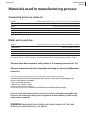
Service and Repair Manual
applies to Sinus 503, Sinus 582 and Sinus 912
equipped with Rotax 503, Rotax 582
and Rotax 912 engines
(all TW and NW versions)
and
Virus 912 equipped with Rotax 912 engine
(all TW in NW versions)
Revision 1
updated 18th June, 2012
This is the original manual of Pipistrel d.o.o. Ajdovščina
Should third-party translations to other languages contain any inconsistencies,
Pipistrel d.o.o. Ajdovščina denies all responsibility.
2 Service manual
pipistrel.si
Index of revisions
Enter and sign the list of revised pages in the manual into the spaces provided below. All revised pages
should be clearly designated in the upper right corner of the page, also, any changes in page content
should be clearly visible (e.g. marked with a bold vertical line)
Name of
revision
Revision 1
Revision no.
Signature, date
date
1, 18th June
2012
Tomazic, Coates
18th June 2012
Description
Checked all spelling in document
US English
Service manual 3
pipistrel.si
List of valid pages
This manual contains 74 original and revised pages listed below.
Cover
Index of revised pages
List of valid pages
Table of contents
General
Servicing the aircraft
Schematics
Repairs
Pages
State
1
Original
2
Original
3
Original
5
Original
7-9
Original
11 - 27
Original
29 - 52
Original
53 - 70
Original
Caution:
This manual is valid only if it contains all of the original and revised pages listed above.
Each page to be revised must be removed, shredded and later replaced with the new, revised page in
the exact same place in the manual.
4 Service manual
pipistrel.si
This page is intentionally left blank.
Service manual 5
pipistrel.si
Table of contents
General
Servicing the aircraft
Schematics
6 Service manual
pipistrel.si
This page is intentionally left blank.
Service manual 7
General
pipistrel.si
General
Introduction
Notes and remarks
Materials used
in manufacturing process
8 Service manual
pipistrel.si
General
Introduction
This manual contains all information needed for appropriate and safe servicing of Sinus ultralight
motorglider models 503, 582, 912 and Virus 912.
In case of aircraft damage or people injury resulting form disobeying instructions in the manual
PIPISTREL d.o.o. denies any responsibility.
All text, design, layout and graphics are owned by PIPISTREL d.o.o. Therefore this manual and any of
its contents may not be copied or distributed in any manner (electronic, web or printed) without the
prior consent of PIPISTREL d.o.o.
IT IS MANDATORY TO CAREFULLY STUDY THIS MANUAL PRIOR TO USE
OF AIRCRAFT
Notes and remarks
Safety definitions used in the manual:
WARNING! DISREGARDING THE FOLLOWING INSTRUCTIONS LEADS TO SEVERE
DETERIORATION OF FLIGHT SAFETY AND HAZARDOUS SITUATIONS, INCLUDING SUCH
RESULTING IN INJURY AND LOSS OF LIFE.
CAUTION! DISREGARDING THE FOLLOWING INSTRUCTIONS LEADS TO SERIOUS
DETERIORATION OF FLIGHT SAFETY.
Service manual 9
General
pipistrel.si
Materials used in manufacturing process
Composite parts are made of:
fabric:
GG160, GG200, 90070, 92110, 92120, 91125, 92140, 92145, KHW200
roving:
NF24
foam:
75 kg/m3 PVC 3mm, PVC 5 mm, PVC 8mm
GFK:
3 mm, 5 mm, 7 mm of thickness
paint:
gelcoat
heat resistant protection
glass-aluminium sandwich
Metal parts used are:
tubes:
materials: Fe0146, Fe 0147, Fe0545, Fe1430, AC 100, CR41 in LN9369
sheet metal:
rods:
materials: Fe0147 in Al 3571
materials: Fe 1221, Fe 4732, Č4130, Al 6082, CR41 in Al 6362
cable:
AISI 316
bolts and nuts:
8/8 steel
All composite parts are made of glass, carbon and kevlar fiber manufactured by Interglas GmbH.
All parts have been tested at safety factor 1.8, meaning stressed to 7,2 G
All parts are made in moulds, therefore no shape or structural differences
can occur.
All designing, manufacturing and testing complies with following regulations:
• Bauvorschriften für Ultraleichtflugzeuge des Deutschen Aero Club e.V. Beauftragter des
Bundes-ministeriums für Verkehr
• JAR-1 microlight definition
• EASA CS-22 - certain sections
• EASA CS-VLA -certain sections
for Slovenian market also: Pravilnik o ultralahkih napravah Republike Slovenije.
All parts and materials presented in all versions of Sinus ultralight motorglider and
Virus 912 are also being used in glider and general aviation industry and all comply
with aviation standards.
WARNING! WHEN SERVICING OR REPLACING PARTS ALWAYS USE THE SAME
MATERIAL AS USED ORIGINALLY (SEE ABOVE).
10 Service manual
pipistrel.si
General
This page is intentionally left blank.
Service manual 11
Servicing the aircraft
pipistrel.si
Servicing the aircraft
Introduction
Repairs and
spare part replacements
Inspection periods
Special check-ups
Fibre reinforced plastic
repairs
Example of flaperon FRP
repair
Example of wing FRP
repair
Weight and Balance
12 Service manual
pipistrel.si
Servicing the aircraft
Introduction
This chapter determines handling and (preventative) maintenance terms. Also, recommended
ground handling is presented.
Repairs, spare part replacements and
preventative maintenance
All major repairs and spare part replacements MUST be done by
authorised service personnel.
However, you are encouraged to take care of preventative maintenance yourself. This includes:
tire and wheel bearings replacements, safety wire replacements, door and safety harness
replacement, light bulb replacements, fuel hose replacements, battery servicing and
replacement, sparks and spark plugs replacements and air filter replacements.
The table below indicates recommended maintenance periods (see Service manual for detailed information).
Table legend:
C Check-up - visual only, check for free play and whether everything is in position - DO IT YOURSELF
CL Cleaning - DO IT YOURSELF
LO Lubricating, oiling - lubricate all designated parts and spots using proper lubricant -
DO IT YOURSELF
R Replacement - replace designated parts regardless of state and condition.
You are encouraged to DO undemanding replacements YOURSELF, otherwise have replacements
done by AUTHORISED SERVICE PERSONNEL
SC Special check-up - measuring, verifying tolerances and functionality - DONE BY AUTHORISED
SERVICE PERSONNEL ONLY
O Overhaul
daily
WING AND TAIL SURFACES
surface and structure condition
deflections without free play
bearings - moving parts’ bushings
lights
self-adhesive sealing tape
horizontal tail mount
drain holes
first 5
50
100
200
500 1.000 10.000
hours hours hours hours hours hours hours
SC
C
C
C
C
C
C
CL
SC
SC
SC
C
C
SC
SC
O
Service manual 13
Servicing the aircraft
pipistrel.si
daily
FUSELAGE
surface and structure condition
elevator control tube bearing
undercarriage struts attaching points
doors, hinges
rudder control wires and hinges
CABIN
control levers, instr. panel, seats
control levers’ free play
instruments and pitot-static
glass surfaces: clean, attached
rivet condition
safety harnesses and attach. points
parachute rescue sys. activation handle
wing connectors: fuel, electrical
bolts and spar pins
wing main bushings, control connectors
UNDERCARRIAGE
tires
main strut, tail /nose wh. strut condition
wheel axis and wheels
hyd. brake lines
brake fluid
brake discs
wheel bearings
tail wheel main bolt
wheel fairings
tail wheel mounting bolt
fist 5
50
100
200
500 1.000 10.000
hours hours hours hours hours hours hours
C
C
C
C
C
C
C
C
C
C
C
C
C
C
C
C
SC
SC
SC
SC
O
SC
O
SC
LO
C
SC
SC
SC
C
check yearly
SC
C
SC
SC
SC
C
C
SC
SC
SC
O
C
C
C
C
C
C
C
C
replace on condition or every 5 years
SC
C
SC
R
SC R (500 hrs or 5 years)
SC
(R on condition)
C
SC
R
C
R
C
SC
R
CONTROLS (LO every 200 hrs or yearly)
C
C
general free play
C
control stick
C
C
rudder pedals (damage, centered, paral.)
C
rudder wire rope
bolts, visible bearings (tail, fuselage)
difficult-to-reach bearings (wings, under cabin floor)
aileron, elevator and rudder hinges
equal spoiler extension, undistributed m. C
C
spoiler plate springs stiffness
C
flap handle
SC
LO
C
SC
SC
SC
LO+SC
SC
SC
LO+SC
LO
C
elevator trim
springs: flaps, rudder, el. trim, stabilizer main fastening bolt
spoilers’ (airbrakes’) drive fine adjustment
SC
R cable every 500 hrs
LO
C
R
see page 15 for detailed description
14 Service manual
pipistrel.si
Servicing the aircraft
daily
ENGINE
first 5 50
100 200 500 1.000 10.000
hours hours hours hours hours hours hours
see enclosed Rotax engine manual for detailed engine maintenance information.
In addition to Rotax manual:
two-stroke engines (overhaul every 300 hours)
four-stroke engines (overhaul every 1,500 hours)
engine cover screws
C
C
engine mount
C
C
engine mount dumpers and other
C
rubber parts
air filters
C
C
elect. terminals, joints and
C
C
connectors, hoses, radiator mount
exhaust muffler
C
C
exhaust pipe springs and fire protect. C
C
throttle, choke, propeller wire drive
ENGINE CONTROL
choke and throttle lever wire ropes
levers
PROPELLER AND SPINNER
surface condition
fastening bolts
propeller bushings
propeller pitch
propeller balance
FUEL SYSTEM
general leakage
water inside gascolator
dirt and gascolator filter
wing fuel tank caps
fuel tank caps o-ring
fuel valves and leakage
ELECTRICAL WIRING
battery
battery fluids
instr.panel wires and connectors
NAV, AC and LDG lights
fuses
C
from engine serial number 4404718
C
SC
R every 500 hrs
SC
or every 5 years
CL
SC
SC
SC
SC
SC
SC
R
R
O
C
C
C
SC
SC
R
SC
O
C
R
R
SC
SC
C
C
O every 1000 hrs or 5 years
C
C
C
CL
SC
CL
CL
R
C
R every 500 hrs or 5 years
C
SC
C
C
C
C
C
C
C
C
SC
SC
C
C
R
Service manual 15
Servicing the aircraft
pipistrel.si
daily
OIL AND WATER LINES
oil and cooling fluids level
oil and cooling fluids leakage
four stroke engine oil (and engine
filter) first 25 hours +
cooling fluid (level)
hoses
radiators
water radiator pressure cap
C
C
first 5 50
100 200 500 1.000 10.000
hours hours hours hours hours hours hours
O every 500 hrs or 5 years
C
C
refer to engine manual
C
C
C
C
refer to engine manual
R
refer to engine manual
SC
PITOT-STATIC LINING
instrument to pitot tube lining
instrument setting
pitot tube condition (clean, firmly att.)
whole pitot-static lining
C
C
C
C
C
C
C
C
Spoilers’ (airbrakes’) drive fine adjustment
CAUTION! Perform this operation only once after first 50 flight hours! Check spoilers
thoroughly for unobstructed, smooth and even extension every 200 flight hours!
Schematic of spoilers’ (airbrakes’) drive fine adjustment
(see next page for detailed description)
2
1
5
3
4
4
O
16 Service manual
pipistrel.si
Perform the adjustment as follows:
1
Unscrew and remove the inner horizontal bolt of the airbrake’s plate. Do not lose any parts!
2
Lift the airbrake in order to make room for further operation.
3
Unscrew and remove the bolt attaching the rod-end bearing to the airbrake’s plate lever.
Do not lose any parts!
4
Rotate the rod-end bearing fine-setting nut 360° so that the rod end moves towards the
other end of the airbrake’s box (length of rod increases). Make sure you secure this nut
after turning it for 360°!
5
Grease the drive around the rubber sleeve inside the airbrake’s box using rubber-nonagressive lubricant spray.
Once you have accomplished this, repeat steps 1-3 in opposite order (3,2,1). Make sure you apply adhesive (e.g. Loctite) on all screws when reattaching!
Perform the procedure at the other airbrake as well. In the end verify airbrakes for equal extension.
WARNING! Should the airbrakes not retract evenly, apply step action 4 again for the airbrake, which remains higher when retracting.
Vital stages of spoilers’ (airbrakes’) drive fine adjustment in pictures
Spoiler’s (Airbrake’s) plate
1
Rod-end bearing
3
4
Horizontal bolt of the AB’s plate
1
pipistrel.si
Service manual 17
Clicking noise overhead
The wings are factory fitted to the fuselage to make a tight fit at approximately 20° Celsius. When exposed to low temperatures, materials shrink. Therefore, flying in the winter or in cold temperatures,
you may encounter “click-clack” like noises above your head. The remedy for this unpleasant noises
is to add washers, typically of 0,5 mm thickness in-between wing and fuselage. Washers must be
added both at rear and front bushings at one side of the fuselage only!
WARNING! It is mandatory to consult the manufacturer or authorised service personnel
before applying washers!
Adjustment of tail wheel steering clutch stiffness
To adjust the stiffness of tail wheel steering clutch you need two allen keys (a.k.a. hex-wrench, inbuskey). On top of the wheel fork you will notice a ring with two tubes welded to each side with hexbolts inside. First disconnect the springs at the tubes, then stick an allen key into each of these tubes
and tighten or loosen the screw inside. Make sure, tightening or loosing, you apply equal number of
screw rotations at both sides. To check if the steering clutch is stiff enough, lift the tail and rotate the
fork left and right. At the end, reattach both springs to the tubes again.
(see Service manual for photos)
Venting the hydraulic brakes’ lining
In case you notice poor braking action even when hydraulic brake levers are depressed fully, it is
most definitely necessary to vent the hydraulic lining. To do so, first unscrew the caps of small fluid
reservoirs (behind rudder pedals on one side of the cockpit) and remove the inner seal cap.
At the side where there are no fluid reservoirs grab the whole rudder pedal and deflect it back fully,
so that it becomes level with the cockpit’s floor beneath. Now, at the side where there are fluid reservoirs, jerk brake levers back and forth a couple of times - this will push air bubbles towards the
reservoir and out of the lining. When convinced air bubbles are no more, put seal caps back onto the
reservoirs and screw the caps on as well. Repeat the procedure for the other brake lever.
WARNING! Should you encounter any difficulties during this procedure or the air bubbles
would not vent, please consult the manufacturer or authorised service personnel for further
instructions.
18 Service manual
pipistrel.si
Schematic of hydraulic brakes’ lining
Poor braking action
In case you notice poor braking action even when hydraulic brake levers are depressed fully, it is not
necessary the air bubbles in the hydraulic lining, which is causing the problem.
The main wheel’s main axis’ nut (especially after a wheel and/or axis replacement nut) may be tightened incorrectly so that the brake shims do not make contact with the brake plate. Please consult
the manufacturer or authorised service personnel for further information.
Schematic of wheel and wheel brakes
Service manual 19
pipistrel.si
Connecting Auxiliary power supplies
Should you be unable to start the engine due to a weak battery, auxiliary power supplies can be connected to help starting the engine.
Battery’s & Relay’s location
Battery (black) & Relay (top-right)
Top-left nipple (c. positive (+) wire here)
Exhaust (connect negative (-) wire here)
To connect an auxiliary power supply use battery connector cables with clamps at either ends.
Connect the negative (-) wire to aircraft’s exhaust (sticking out below the engine cowlings).
The positive (+) wire leads inside the cockpit to the relay mounted top-right of the aircraft’s battery
on the firewall. This relay has 3 nipples; the positive (+) wire must be connected to the upper-left
nipple, the only one to which 2 cables are connected to.
After you have connected the wires correctly, start the engine normally by pressing the starter button in the cockpit.
WARNING! The pilot must be in cockpit when starting the engine. The person who will
disconnect the cables after the engine has started must be aware of the danger of spinning
propeller nearby.
20 Service manual
Servicing the aircraft
pipistrel.si
Fibre reinforced plastic repairs
WARNING! Do not, under any circumstances attempt to repair damages greater than 50 mm
in size (on wing) and/or 20 mm in size on any control circumstances. These require a treatment by
a FRP professional!
Definition of minor damage
Only the damage listed below can be considered as minor damage repairable by oneself.
Any damage limited to gelcoat or filler.
Holes in the fuselage underside where the average diameter does not exceed:
Forward fuselage: 50 mm
Rear fuselage: 50 mm
Cracks in fuselage underside max.
Forward fuselage: 50 mm
Rear fuselage: 50 mm
The fuselage glued joint (rear fuselage) should not be damaged.
Holes, cracks and tears, bubbles etc. in the wings, horizontal stabilizer and control surfaces skins
where the damage does not exceed (average diameter crack length):
Wings: 50 mm (50 mm)
Horizontal stabilizer: 20 mm (20 mm)
Rudder: 20 mm (20 mm)
Flaperon, Elevator: 20 mm (20 mm)
The above parts should not be damaged in the spar area.
Damaged fittings should not be repaired but replaced.
Facilities
To insure proper curing, the room temperature during repair work and at least 12 hours afterwards
should be maintained at 21°C (70° F). After that the repaired parts are to be tempered. Therefore you
may construct a tempering tent, using plastic film or Styrofoam plates.
Filler
For gluing, the resin-hardener mix should be thickened with chopped cotton fibres FL l f. (add
enough so that the resin no longer flows). The surfaces to be glued should be wetted with non-thickened resin & hardener before.
To glue foam pieces into place when repairing sandwich sections and to fill in irregularities and
gaps etc. around the repair, Microballoons BJO - 0930 can be used mixed with the resin-hardener.
Application and mixing is the same as for the cotton flocks.
WARNING! Only materials listed on page 9 should be used. Only damage defined above
should be repaired.
pipistrel.si
Service manual 21
Repair method for FRP
Cut out damaged area, roughen the surrounding area for the overlap required. Repairs should be
made such that bonding is wet over dry. Specific details concerning handling and using fibre reinforced plastics can be obtained from various publications ie. “Petite Plane Patch Primer.”
The use of Carbon fibre is the same as for glassfibre, except that the carbon fibres should not be
kinked and only the specified resins are used.
WARNING! All repairs should be tempered for 20 hours at 54°C before the next take off.
Repairs of the FRP shell
Prepare the repair area as specified above. Scarf the shell so that the individual layers of fabric can be
seen like plywood layers. Remove the gelcoat for at least 20 mm around the damaged area.
Repairing the outer skin of a sandwich panel
Cut out the damaged area, remove the gelcoat over the overlap area and 10 mm around the damaged area. Fill the damaged foam area with resin thickened with microballoons (microballoons-resin), let harden. Sand down. With a round headed hammer tap the outer skin around the hole so that
the foam is somewhat compressed, therefore heat this area to ca. 60°C (140°F). Apply the new cloth.
Repair of outer and inner skin of a sandwich panel
Additionally remove as much foam as is needed so that the entire damage to the inner skin can be
seen plus enough undamaged inner skin as is required for overlapping. If the inner skin still holds
together, sand properly and lay up the new cloth over it. Insert a suitable cut piece of foam, 1-2 mm
thinner than the original, glued in with microballoons-resin. Should the inner skin be so damaged
that the above process cannot be use the inner skin fabric should be applied to the foam first and
left to harden before inserting into the repair area. Microballoons-resin should once again be used.
For lay up of the fabric to the foam, a layer of microballoons-resin should be applied first to eliminate
the formation of air bubbles. Apply outer layers
Special hints for processing aramid fibres
The difficulties processing aramid fibre starts already when cutting the fabric. Only with very sharp
tools (toothed scissors) cutting the material is possible. Sanding the fibres is not possible without
formation of fluff or fuzz. Only wet sanding is feasible. After sanding, the area must be dried with a
fan heater.
Aramid fibre has the tendency to take up humidity. Therefore dry storage and drying the fibres prior
to processing is necessary. Aramid must be protected against UV-rays before and after processing.
An aramid repaired area must be protected by a paint with UV-protection. Thin aramid layers can’t
be scarfed. Only overlapping is possible.
Repair of the carbon fibre - aramid fibre – hybrid fuselage shell
With this construction the repair method see mentioned above is not applicable. Contact the manufacturer.
22 Service manual
pipistrel.si
Repairing small dents in a sandwich panel skin
(no cracks in the gelcoat)
Small dents can usually be removed by heating up to 60° to 70° C (140° -158°F). Use a hot air blower
to heat the area of the dent. The crushed foam will then spring back to its original form, so that the
dent will hardly be seen. Final sanding with wet sandpaper grade 600 should finish the job. In more
severe cases, one coat of gelcoat will remove all trace of the dent.
Outer skin finish
Repairs should be such that the area is exactly level or only slightly higher than the surrounding skin
surfaces. Sand the hardened repair surface with dry grade 80 sandpaper. Fill with Polyester filler, let
dry and sand with dry sandpaper. When the surface is smooth, sand the repair area and at least 5 cm
(2 in.) of the surrounding gelcoat with wet sandpaper grade 400. Spray the repair area with 5 coats of
gelcoat.
After the gelcoat has hardened, sand with grade 400, 600 and 800 wet sandpaper until the surface is
smooth. Polish with a power buffer (electric drill or similar with cloth polishing wheel). Apply a block
of wax onto the rotating polishing wheel and then polish the repaired area. Do not polish in only
one direction, and do not polish one spot for too long to prevent material overheating.
WARNING! After repairing control surfaces, the mass balance weights MUST be checked
again with the values given in the maintenance manual. Should the maximum values be exceeded, then the parts have to be replaced.
pipistrel.si
Service manual 23
Example of flaperon FRP repair
WARNING! Do not, under any circumstances attempt to repair damages greater than 50 mm
in size (on wing) and/or 20 mm in size on any control circumstances. These require a treatment by
a FRP professional!
Phase I
Carefully cut and remove the damaged foam (Herex 3
mm) in width of at least 20 mm around the damaged
area.
Clean the area, paying special attention that the inner
fabric is immaculate. This is of vital importance. After
you have cleaned and rinsed everything, laminate the
20 mm area according to the laminate-plan shown on
the drawing below.
Laminate plan for flaperon
WARNING! if the damage area is located on the flap hinge (the fabric used there is carbon
fibre - black color) you must laminate using one ply of GG160 fabric, oriented diagonally to the
flight direction. Also, you must apply Peel Ply on top of GG160.
24 Service manual
pipistrel.si
Phase II
Remove the Peel Ply and adapt a new piece of foam (Herex 3 mm) as accurately as you possibly can
and glue it with microballoons.
WARNING! Do not apply too much pressure anywhere!
Phase III
Grind the foam if its level is too high. Also grind the external laminate around the cut-out for about
25 mm in a conical-shape (see next drawing). When done, laminate as follows:
- Place one (1) piece of GG160 diagonally and
- One (1) piece of 90070 perpendicular to the flight direction.
Phase IV
Grind only the outer edge of the new fabric. When done, the new surface is ready to be painted.
pipistrel.si
Drawing of skin final repair
Service manual 25
26 Service manual
pipistrel.si
Example of wing FRP repair
WARNING! Do not, under any circumstances attempt to repair damages greater than 50 mm
in size (on wing) and/or 20 mm in size on any control circumstances. These require a treatment by
a FRP professional!
Phase I
Preparing the surface. Carefully clean the damaged foam and check if there is also a damage on the
inner fabric.
If the inner fabric in not damaged fill the hole with microballoons as you can see on the drawing below. In case the hole is through the inner fabric as well, you have to repair the inner fabric, too.
The new patch must be at least 20mm bigger than the damaged area. You also have to replace (glue)
the missing foam with a new one.
Gap filling drawing
pipistrel.si
Service manual 27
Phase II
Laminating. Grind the outer fabric in a shape of a cone at least 25mm around the damaged area (see
drawing below) and laminate only the ground surface with fabrics as follows:
- Two (2) pieces of 92110 and
- One (1) piece of 90070
When laminating be careful about the orientation of the fibres. The fibres of 92110 must be put diagonally to the flight direction, the fibres of 90070 must be put perpendicular to this direction. The
directions are also shown in the drawing below.
Phase III
Grinding. You can grind only the surface (ring) around the damaged area. This surface is shawn in
previous drawing. When done the surface is ready for painting.
28 Service manual
pipistrel.si
Weight and balance
Weight and Balance
This chapter provides information on aircraft’s weight and balance, which is essential for safe flying
activity.
Procedure
How to weigh the aircraft and later determine the CG correctly:
Make sure all listed aircraft parts and appliances are installed and in position.
Remove all other objects (e.g. tools, mops ...).
Empty fuel tanks except for the unusable fuel.
Fill up engine oil to the top marking.
Retract flaps and spoilers, leave control surfaces centred.
Support fuselage at the rear and level the aircraft inside a closed space.
To do this, use the provided airfoil template at lower side of the wing close to the wing root
and make sure its straight edge is level (horizontal).
Once leveled, read the scale readings and subtract eventual tare weight.
Now measure and record all readings and fill out the bottom schematic.
Datum is wing’s leading edge at wing root.
CG lever arm formula for Tail-wheel aircraft (Sinus TW, Virus TW, any model):
Lever arm of CG (X) = ((G2 / G) x b) + a
CG lever arm formula for Nose-wheel aircraft (Sinus NW, Virus NW, any model):
Lever arm of CG (X) = ((G1 / G) x c) - a
Weighing form (TAILWHEEL)
Weighing point and symbol
right main wheel (GD)
left main wheel (GL)
tail wheel (G2)
total (G = GD + GL +G2)
Scale reading
Tare
Nett
Service manual 29
Weight and balance
pipistrel.si
Determination of CG
Weight (kg)
Weight’s lever
arm (cm)
Torque (kg/cm)
Remarks
Basic cfg. empty weight
CAUTION! Each newly installed part or appliance must be registered in the upper table. Also,
new total weight and lever arm of CG values must be entered and position of CG re-determined.
Furthermore, the momentum must be recalculated. This is rather easy to do. First multiply the
new part’s weight by it’s lever arm measured from the reference point (wing’s trailing edge). Then
sum up all moments and divide the sum by the new total weight.
WARNING! Regard to the Flight manual and Maintenance manual for allowable C.G. limitations!
30 Service manual
pipistrel.si
Sample c.g. calculation
Guidelines
Gtotal is the total mass of empty aircraft. All calculations can be performed with aircraft empty
weight and empty weight centre of gravity (c.g.), as the pilots sits directly below the centre of gravity
and do not cause the c.g. to be shifted. The amount of fuel quantity also has no impact on the c.g..
WARNING! Both pilots’ weight and weight of fuel do not influence c.g. or their influence is
insignificant. However, baggage can influence the c.g. severely and may cause the aircraft to
become uncontrollable!
Basic CG formulas and calculation
The below instructions are valid for Virus Tail Wheel and Nose Wheel editions. Read thoroughly. Note
also that the basic c.g. at 287 mm will be used purely as an example.
First, weigh the aircraft according to the procedure described in this chapter and write down values
of G1 (sum of scale readings at main wheels) and G2 (scale reading at tail/front wheel). Then calculate the position of c.g. in millimeters (mm) from the datum (wing’s leading edge at wing root).
For Tail wheel edition of Virus use the following formula:
CGmm =
G2 tail x b
+a=
G2tail x 4300 mm
Gtotal
+ 110mm = 287mm
Gtotal
where:
G2tail is the scale reading at the tail wheel,
Gtotal is the sum of G1 and G2tail (G1+G2tail), a.k.a. aircraft empty weight
a is the distance from main wheel axis to wing’s leading edge,
b is the distance between main and tail wheel axis.
For Nose wheel edition of Virus use the following formula:
CGmm =
G1back x c
-a=
G1back x 1525 mm
Gtotal
- 1020mm = 287mm
Gtotal
where:
G2back is the sum of scale readings at both main (back) wheels,
Gtotal is the sum of G1 and G2back (G1+G2back), a.k.a. aircraft empty weight
a is the distance from nose wheel axis to wing’s leading edge,
b is the distance from main wheel axis to wing’s leading edge,
c = (a+b) is the sum of both distances above.
Second, determine the c.g. position in percentage (%) of Mean Aerodynamic Chord (MAC) with following the formula:
CG%MAC =
CGmm - R
MAC
287mm - 29mm
x 100 =
x 100 = 28.4%
908mm
where:
CGmm is the position of CG in millimeters (mm),
R is the difference between wing’s leading edge and MAC’s leading edge (29 mm),
MAC is the Mean Aerodynamic Chord (908 mm, for Sinus it is 869 mm).
Service manual 31
pipistrel.si
Schematics
Control levers
Wings
Tail surfaces
Undercarriage
Brakes
Fuel system
Engine cooling system
Engine lubrication system
Throttle and choke drive
Electrical system
Flap handle, 1
Control levers
Schematics
32 Service manual
UVM
243
648
50
250
500
1000
multi-purpuse grease
Loctite 243
Loctite 648
ABBEREVIATIONS
100
INSPECTION PERIODS
hand insp.
oil
grease
glue
SYMBOLS
pipistrel.si
Flap handle, 2
pipistrel.si
UVM
243
648
50
250
500
1000
multi-purpuse grease
Loctite 243
Loctite 648
ABBEREVIATIONS
100
INSPECTION PERIODS
hand insp.
oil
grease
glue
SYMBOLS
Service manual 33
Schematics
Control stick
Schematics
34 Service manual
UVM
243
648
50
250
500
1000
multi-purpuse grease
Loctite 243
Loctite 648
ABBEREVIATIONS
100
INSPECTION PERIODS
hand insp.
oil
grease
glue
SYMBOLS
pipistrel.si
Rudder pedals
pipistrel.si
UVM
243
648
50
250
500
1000
multi-purpuse grease
Loctite 243
Loctite 648
ABBEREVIATIONS
100
INSPECTION PERIODS
hand insp.
oil
grease
glue
SYMBOLS
Service manual 35
Schematics
Flap levers
Schematics
36 Service manual
UVM
243
648
50
250
500
1000
multi-purpuse grease
Loctite 243
Loctite 648
ABBEREVIATIONS
100
INSPECTION PERIODS
hand insp.
oil
grease
glue
SYMBOLS
pipistrel.si
wing’s exterior
Wings
pipistrel.si
UVM
243
648
50
250
500
1000
multi-purpuse grease
Loctite 243
Loctite 648
ABBEREVIATIONS
100
INSPECTION PERIODS
hand insp.
oil
grease
glue
SYMBOLS
Service manual 37
Schematics
wing’s interior
Schematics
38 Service manual
UVM
243
648
50
250
500
1000
multi-purpuse grease
Loctite 243
Loctite 648
ABBEREVIATIONS
100
INSPECTION PERIODS
hand insp.
oil
grease
glue
SYMBOLS
pipistrel.si
Airbrake - spoiler
pipistrel.si
UVM
243
648
50
250
500
1000
multi-purpuse grease
Loctite 243
Loctite 648
ABBEREVIATIONS
100
INSPECTION PERIODS
hand insp.
oil
grease
glue
SYMBOLS
Service manual 39
Schematics
horizontal tail surfaces
Tail surfaces
Schematics
40 Service manual
UVM
243
648
50
250
500
1000
multi-purpuse grease
Loctite 243
Loctite 648
ABBEREVIATIONS
100
INSPECTION PERIODS
hand insp.
oil
grease
glue
SYMBOLS
pipistrel.si
vertical tail surfaces
pipistrel.si
UVM
243
648
50
250
500
1000
multi-purpuse grease
Loctite 243
Loctite 648
ABBEREVIATIONS
100
INSPECTION PERIODS
hand insp.
oil
grease
glue
SYMBOLS
Service manual 41
Schematics
tail wheel (Sinus, all models)
Undercarriage
Schematics
42 Service manual
UVM
243
648
50
250
500
1000
multi-purpuse grease
Loctite 243
Loctite 648
ABBEREVIATIONS
100
INSPECTION PERIODS
hand insp.
oil
grease
glue
SYMBOLS
pipistrel.si
hydraulic brakes’ drive
Brakes
pipistrel.si
UVM
243
648
50
250
500
1000
multi-purpuse grease
Loctite 243
Loctite 648
ABBEREVIATIONS
100
INSPECTION PERIODS
hand insp.
oil
grease
glue
SYMBOLS
Service manual 43
Schematics
Rotax 912 (no fuel return circuit)
Fuel system
Schematics
44 Service manual
pipistrel.si
Rotax 912 (fuel return circuit)
Fuel system
pipistrel.si
Service manual 45
Schematics
Rotax 582
Schematics
46 Service manual
pipistrel.si
Rotax 912
Engine cooling system
pipistrel.si
Service manual 47
Schematics
Rotax 582
Schematics
48 Service manual
pipistrel.si
Rotax 912
Engine lubrication system
pipistrel.si
Service manual 49
Schematics
Rotax 912
Throttle and choke drive
Schematics
50 Service manual
pipistrel.si
Rotax 582
pipistrel.si
Service manual 51
Schematics
NAV lights & strobes
Electrical system
Schematics
52 Service manual
pipistrel.si
electrical circuit
pipistrel.si
Service manual 53
Schematics
54 Service manual
pipistrel.si
This page is intentionally left blank.
Service manual 55
Schematics
pipistrel.si
Repairs
Elevator vertical pushrod replacement
VARIO Propeller Assembly
VARIO Propeller Drive Replacement
VARIO Propeller Bearing Replacement
3-Bladed Fixed Pitch Propeller
Airbrake Control’s Drive Reinforcement (1)
Airbrake Control’s Drive Reinforcement (2)
Flaperon Hinge Replacement
Flaperon Lateral Drive Assembly
Flaperon Mass Balance Weights Installation
Wheel Brake (cockpit side) Assembly
Hydraulic Fluid Lines Assembly (wheel side)
Airbrake Handle Assembly
Airbrake Guidance Installation
Venting the Hydraulic Brake Lines
Wheel Brake Repair
Nose Wheel Strut Assembly
Elevator Vertical Pushrod Replacement
Repairs
56 Service manual
pipistrel.si
VARIO Propeller Assembly
pipistrel.si
Service manual 57
Repairs
VARIO Propeller Drive Replacement
Repairs
58 Service manual
pipistrel.si
VARIO Propeller Bearing Replacement
pipistrel.si
Service manual 59
Repairs
3-Bladed Fixed Pitch Propeller Assembly
Repairs
60 Service manual
pipistrel.si
Airbrake Control’s Drive Reinforcement (part 1)
pipistrel.si
Service manual 61
Repairs
pipistrel.si
Repairs
62 Service manual
Wing Control’s Drive Reinforcement (part 2)
Flaperon Hinge Reinforcement
pipistrel.si
Service manual 63
Repairs
Flaperon Lateral Drive Assembly
Repairs
64 Service manual
pipistrel.si
Flaperon Mass Balance Weights Installation
pipistrel.si
Service manual 65
Repairs
Wheel Brake (cockpit side) Assembly
Repairs
66 Service manual
pipistrel.si
Service manual 67
Repairs
pipistrel.si
Hydraulic Fluid Lines Assembly (wheel side)
Airbrake Handle Assembly
Repairs
68 Service manual
pipistrel.si
Airbrake Guidance Installation
pipistrel.si
Service manual 69
Repairs
Venting the Hydraulic Brake Lines
Repairs
70 Service manual
pipistrel.si
Wheel Brake Repair
pipistrel.si
Service manual 71
Repairs
Repairs
72 Service manual
pipistrel.si
Nose Wheel Strut Assembly
Pipistrel d.o.o. Ajdovščina
podjetje za alternativno letalstvo
Goriška cesta 50a
5270 Ajdovščina
Slovenija
tel: +386 (0)5 3663 873
fax: +386 (0)5 3661 263
e-mail: [email protected]
www.pipistrel.si