1
‘B-52 Driver’ FLIGHT MANUAL PART III – Normal Procedures
DO NOT USE FOR FLIGHT
PART III - Normal Procedures
Captain Sim is not affiliated with any entity mentioned or pictured in this document.
All trademarks are the property of their respective owners.
© 2010 Captain Sim www.captainsim.com
1
‘B-52 Driver’ FLIGHT MANUAL PART III – Normal Procedures
DO NOT USE FOR FLIGHT
2
ABOUT THIS MANUAL
VERSION: 13 DECEMBER, 2010
WARNING: THIS MANUAL IS DESIGNED FOR MICROSOFT® FSX USE ONLY. DO NOT USE FOR FLIGHT.
The ‘B-52 Driver’ FLIGHT MANUAL is organized into three Parts.
Each Part is provided as a separate Acrobat® PDF document:
•
Part I – User’s Manual
•
Part II – Aircraft Systems
•
Part III – Normal Procedures - this document.
FOR GENERAL INFORMATION ON THE ‘B-52 DRIVER' PRODUCT PLEASE USE WWW.CAPTAINSIM.COM .
THIS MANUAL PROVIDES ADDITIONAL INFORMATION ONLY, WHICH IS NOT AVAILABLE ON THE WEB SITE.
© 2010 Captain Sim www.captainsim.com
‘B-52 Driver’ FLIGHT MANUAL PART III – Normal Procedures
DO NOT USE FOR FLIGHT
CONTENTS
Page
5
SECTION I
5
NORMAL PROCEDURES
6
‘PREFLIGHT CHECK
6
7
7
EXTERIOR INSPECTION
INTERIOR INSPECTION CHECKLIST (LEFT SEAT)
INTERIOR INSPECTION CHECKLIST (RIGHT SEAT)
7
BEFORE STARTING ENGINES
7
BEFORE STARTING ENGINES CHECKLIST
8
STARTING ENGINES AND BEFORE TAXIING
8
STARTING ENGINES AND BEFORE TAXIING CHECKLIST
11
TAXIING
11
12
12
LANDING GEAR PATHS WING TIP PATHS
TAXIING CHECKLIST
BEFORE LINE-UP CHECKLIST
13
TAKEOFF
13
16
17
TAKEOFF PERFORMANCE
TAKEOFF PROCEDURES
TAKEOFF CHECKLIST
18
AFTER TAKEOFF
20
20
20
20
AFTER TAKEOFF - CLIMB CHECKLIST
CLIMB
CRUISE
RANGE
21
LOW ALTITUDE TACTIC
21
21
LOW LEVEL DESCENT CHECKLIST
CLIMB AFTER LOW LEVEL CHECKLIST
22
DESCENT
22
DESCENT AND LANDING CHECKLIST
24
BEFORE LANDING
29
LANDING
30
31
32
CROSSWIND LANDING
MINIMUM RUN LANDING
LANDING CHECKLIST
33
GO-AROUND
34
GO-AROUND CHECKLIST
© 2010 Captain Sim www.captainsim.com
3
‘B-52 Driver’ FLIGHT MANUAL PART III – Normal Procedures
DO NOT USE FOR FLIGHT
34
TOUCH-AND-GO LANDING
35
35
TOUCH-AND-GO LANDING CHECKLIST
TRAFFIC PATTERN CHECKLIS
36
TAXI-BACK LANDING
36
TAXI-BACK LANDING CHECKLIST
37
AFTER LANDING
37
38
AFTER LANDING CHECKLIST
BEFORE LEAVING AIRCRAFT CHECKLIST
39
SECTION II
39
ALL WEATHER OPERATION
39
40
40
41
43
INSTRUMENT TAKEOFF AND INITIAL CLIMB
INSTRUMENT CRUISE
HOLDING
TYPICAL DESCENTS AND PENETRATIONS
INSTRUMENT APPROACHES
48
CUSTOMER CARE
© 2010 Captain Sim www.captainsim.com
4
‘B-52 Driver’ FLIGHT MANUAL PART III – Normal Procedures
DO NOT USE FOR FLIGHT
5
SECTION I
NORMAL PROCEDURES
This section contains text, performance data, flight profiles and an amplified checklist. The text is divided
into primary paragraphs which form the phases of a normal flight. Most of these paragraphs are followed by
an amplified checklist for the particular phase of the flight. The amplified checklist is presented in a
chronological form that will enable the pilot to complete his inspection, checks, and operation of the aircraft
in an expedient yet thorough manner. The amplified checklist describes in detail the steps to be completed.
The terms "As required, " "As desired, " "Climatic," and "Cross-checked" as used in the checklist indicates
equipment operation or settings which may vary according to prevailing conditions. In practice, the response
to these items will be the required switch or control position or actual indicator reading. The amplified
checklist has also been designed to accommodate the production of the abbreviated checklist to be used
during aircraft operation.
This manual based on original B-52 flight manual and adapted for a single-pilot FSX environment.
© 2010 Captain Sim www.captainsim.com
‘B-52 Driver’ FLIGHT MANUAL PART III – Normal Procedures
DO NOT USE FOR FLIGHT
6
PREFLIGHT CHECK
EXTERIOR INSPECTION
NOTE
•
Because of the size and complexity of the aircraft, the detailed inspection will have been completed
by qualified ground crew personnel. The flight crew exterior inspection is an inspection of general
aircraft condition. This inspection is based on the assumption that the flight crew is merely
accepting the aircraft for flight with emphasis on the items that affect the safety of flight. During
the inspection, emphasis will be directed toward a checking for hydraulic leaks, fuel leaks, and
general condition.
© 2010 Captain Sim www.captainsim.com
‘B-52 Driver’ FLIGHT MANUAL PART III – Normal Procedures
DO NOT USE FOR FLIGHT
7
INTERIOR INSPECTION CHECKLIST (LEFT SEAT)
1.
2.
3.
Autopilot Servos Cutout Switches
Antiskid Switch
Mach Indicator Switch
OFF
ON, guard closed
ON
NOTE
•
The mach indicator will be unreliable and needle oscillation may occur until
sufficient pitot pressure is attained during takeoff. The pilot should expect and disregard
this oscillation.
4.
5.
6.
7.
8.
9.
10.
Hydraulic Standby Pump Switches
Rudder/Elevator Hydraulic Switches
Clock
Anti-Icing Switches
Yaw SAS Switch
Airbrake Lever
Crosswind Crab Knob & Indicator
OFF
OFF
Checked and set
OFF
DISENGAGE
OFF
Zero
INTERIOR INSPECTION CHECKLIST (RIGHT SEAT)
1.
2.
3.
4.
5.
6.
7.
8.
9.
10.
11.
Battery Switch
Engine Starter Switches
Frequency And Voltmeter Selector Switch
Generator Drive Decoupler Switches
Clock
All Fuel System Switches
Landing Gear Lever
Throttles
Drag Chute Lever
Wing Flap Lever
Terrain Display Mode Selector Switch
OFF
OFF
CENTRAL BUS TIE
Checked in NORM
Checked and set
OFF and CLOSED
GEAR DOWN
CLOSED
Checked
OFF
OFF
BEFORE STARTING ENGINES
BEFORE STARTING ENGINES CHECKLIST
1.
2.
3.
4.
5.
6.
7.
8.
9.
Gyro Power Switch
ON
Battery Switch
ON
Generator Switches
OFF
Momentarily position generator switches to OFF and check generator circuit breakers open and bus
tie circuit breakers closed.
External Power Switch
ON (if available)
Oxygen Quantity
Checked
Fuel Quantity Check
Completed
Navigation Lights
ON
Radios
CHECK
NAV equipment
CHECK as follows:
(1)
Nav Mode Select Switch - VOR
(2)
Check that bearing pointer points to the station.
(3)
Rotate course set knob and check that TO changes to FROM indication
(a)
DME alive.
10.
Elevator & Rudder
Checked
a.
Rudder/Elevator Hydraulic Switches - ON, lights out; Check main and aux hydraulic system
lights out.
b.
Elevator Check:
(1)
Control Column
Full forward
Ground observer reports position of elevators.
(2)
Control Column
Full back
Ground observer reports position of elevators.
c.
Rudder & Rudder Trim Check:
© 2010 Captain Sim www.captainsim.com
‘B-52 Driver’ FLIGHT MANUAL PART III – Normal Procedures
DO NOT USE FOR FLIGHT
8
(1) Rudder Pedal
Ground observer reports position of rudder.
Full left
(2)
Rudder Pedal
Full right
Ground observer reports position of rudder.
(3)
Rudder Pedals & Rudder Trim Knob - Centered Ground observer reports position of rudder.
e. Rudder/Elevator Hydraulic Switches
OFF
11.
Standby Hydraulic Pump Pressure
Checked
12.
Autopilot
Checked and OFF
a.
Check turn knob and roll trim knob
b.
Place autopilot master switch ON.
c.
Note trim indicators centered and place servos engage switch to ENGAGE.
d.
Disengage autopilot - the disengage caution light should come on.
e.
Turn autopilot master switch OFF.
13.
Airbrake, Spoiler & Lateral Trim Check
Completed
•
This check is made in coordination with ground crew observer. Ground crew observer will
report position of spoilers after each movement.
•
Spoiler rigging tolerances are such that the spoiler groups on each wing may not exactly
line up during partial or full extension of the spoilers.
a.
(1)
Airbrake & Spoiler Check:
Move airbrake to position 6. Ground reports: Inboard 60°; outboard 60°.
NOTE
•
Wing droop associated with high grogs weight fuel loads may make it impossible
to see the outboard airbrake segments from the cockpit.
(3) Airbrake lever - OFF. Ground reports, "All airbrakes down. "
14.
Wing Flaps
Checked and up, lever OFF
Flaps should be full down at the time the crew enters the aircraft. Flaps should be checked that they retract
in approximately 60 seconds.
15.
16.
17.
18.
Fuel Panel Switches:
Gyro Instruments
Oxygen Regulator
Bomb Doors
Checked
Checked
OFF and 100% OXYGEN (if leaving the
aircraft for an extended period of time)
Close
Bomb doors will be closed and remain closed on alert aircraft except for required maintenance and special
weapons inventory.
STARTING ENGINES AND BEFORE TAXIING
STARTING ENGINES AND BEFORE TAXIING CHECKLIST
1.
PARKING BRAKES
SET
2.
BATTERY SWITCH
ON
3.
External Power
ON (if available)
4.
Generator Switches
OFF
Momentarily position generator switches to OFF one at a time and check generator circuit breakers open and
bus tie circuit breakers closed.
5.
Ground, Close Hatches
Roger
WARNING
•
The MA-3 external air conditioning unit can build up sufficient cabin pressure to
cause the entrance hatch to blow. Ascertain that a sliding window is open prior to opening
or closing the hatch.
© 2010 Captain Sim www.captainsim.com
‘B-52 Driver’ FLIGHT MANUAL PART III – Normal Procedures
DO NOT USE FOR FLIGHT
9
6.
7.
8.
START ENGINES
STARTED
ENGINE ANTI-ICING SWITCH
CLIMATIC
GENERATORS
ON
a. Momentarily hold each generator switch ON to energize the generator field and close the
generator circuit breakers (the generators will parallel). b.
Check that generator and bus tie circuit breaker position indicators show closed and
generator ammeter readings are the same.
c.
Using the voltage and frequency selector, check voltage at 205 (±5) volts and frequency at
400 (±5) cps on central tie bus, Leave voltage and frequency switch on CENTRAL TIE BUS position.
9.
10.
11.
12.
Ground, Clear Aircraft for Taxi
RUDDER/ELEVATOR HYDRAULIC SWITCHES
Hydraulic System Pressures
Stabilizer Trim
Roger
ON, LIGHTS OUT
Checked
Checked, takeoff trim set
NOTE
For thruflight sorties set stabilizer trim for takeoff. No other checks are required.
13.
14.
Oxygen Regulator
Bomb Doors (Internal Munitions Only)
As required
Closed
Bomb doors will be closed at this time if internal munitions are aboard. Ground personnel will confirm that
bomb doors are clear. Pilot will place the bomb door switch to OPEN to insure that both latches are
unlatched, check that the bomb doors not latched light is on, and then place the switch to CLOSED.
NOTE
Whenever bomb bay is empty or during any alert scramble, the bomb doors will be closed while
accomplishing the taxiing checklist.
15.
ANTICOLLISION & NAVIGATION LIGHTS
ON
Turn lights on immediately prior to taxiing to indicate the aircraft is ready to taxi.
16.
TAXI ON CREW CHIEF'S SIGNAL
Pilot announces "Crew stand by to taxi"
•
CAUTION
Wing flaps must be up. Pilot taxies aircraft straight ahead until ground crew signals that he is clear
of the power units. As soon as the aircraft starts rolling, throttles will be retarded to minimum
thrust required for taxiing to avoid upsetting the power carts by jet blast. Aircraft must be
positioned so that no aircraft will have to taxi over the power carts of another aircraft.
© 2010 Captain Sim www.captainsim.com
‘B-52 Driver’ FLIGHT MANUAL PART III – Normal Procedures
DO NOT USE FOR FLIGHT
© 2010 Captain Sim www.captainsim.com
10
‘B-52 Driver’ FLIGHT MANUAL PART III – Normal Procedures
DO NOT USE FOR FLIGHT
11
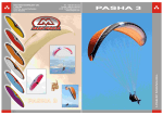
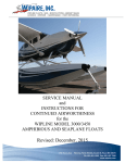
TAXIING
The pilot will release his brakes upon receiving "Clear to Taxi" signal from the crew chief. When the aircraft
starts to roll, a check of brakes should be made. To steer the aircraft, use rudder pedals. Differential braking
is not possible and thrust from the outboard engines is ineffective for turning unless used in conjunction with
normal steering. Use the largest radius of turn possible and never attempt to steer when the aircraft is not
rolling.
LANDING GEAR PATHS WING TIP PATHS
TURNING RADIUS AND GROUND CLEARANCE
CAUTION
Use caution when taxiing over wet painted areas because braking conditions may deteriorate to the extent
that the braking coefficient is near that for an icy condition.
© 2010 Captain Sim www.captainsim.com
‘B-52 Driver’ FLIGHT MANUAL PART III – Normal Procedures
DO NOT USE FOR FLIGHT
12
TAXIING CHECKLIST
1.
BRAKES
CHECKED
Check wheel brakes for proper operation as soon as possible after aircraft starts to move. Pilots monitor
master and central caution lights while taxiing.
CAUTION
•
Do not attempt to use crosswind crab when aircraft is not rolling as severe loads
would be applied to tires and landing gear.
2.
FLAP LEVER
Pilot lowers flaps after taxiing to insure clearance from ground equipment.
DOWN
3.
BOMB DOORS
CLOSED
Pilot places bomb door switch to OPEN to insure that both latches are unlatched, checks that the not latched
light is on, and then places the switch to CLOSED position.
5.
FLIGHT INSTRUMENTS
CHECKED
Check needle for turn indication and ball for freedom of movement; attitude indicator erected and OFF flag
out of sight; standby attitude indicator erected and OFF flag out of view; heading indicators for movement in
turns; and all pitot-static pressure instruments for correct indications.
6.
Generator Panel
Pilot checks ammeters, frequency meter, and voltmeter.
Checked
7.
Crosswind Crab - Checked
If conditions permit, check operation of the crosswind crab to insure positive response in both directions.
Manually turn the crosswind crab knob in each direction, recentering the crosswind crab control with the
centering button in each instance. Check both indicator needles for correct indication. BEFORE LINE-UP CHECKLIST
1.
2.
3.
4.
5.
Parking Brakes
Pitot Heat
YAW SAS SWITCH
Control Surface Trim
STABILIZER TRIM
Set
ON
ENGAGE
Set
CHECKED FOR TAKEOFF SETTING
NOTE
•
During flight, the stabilizer trim switch should be operated in short intermittent
bursts to aid in recognizing a malfunctioning electrical trim system before reaching an
extreme out-of-trim condition.
6.
7.
8.
9.
Airbrake Lever
WING FLAPS
Fuel Panel Switches
WINDOWS & HATCHES
OFF
100%, LEVEL DOWN
Checked
CLOSED AND LOCKED
10.
Flight Instruments
Rechecked and set
a.
The pilot will announce the latest altimeter setting and the known elevation. The pilot will altimeters
within 75 feet of the known elevation.
b.
The pilot will announce his HSI and magnetic standby compass indications. The pilot will crosscheck the instruments for errors.
d.
Pilot and pilot set attitude indicators to indicate level flight.
11.
Radio Navigation Instruments
Checked VOR/TACAN
12.
Lights
ON (P/CP)
Turn landing, taxi, and crosswind landing lights on for night or day operations unless reflection reduces pilot
visibility.
© 2010 Captain Sim www.captainsim.com
‘B-52 Driver’ FLIGHT MANUAL PART III – Normal Procedures
DO NOT USE FOR FLIGHT
13
TAKEOFF
TAKEOFF PERFORMANCE
PERFORMANCE DATA
All takeoff performance data should be determined prior to takeoff. This assures accurate planning and close
monitoring of all takeoffs. These data include such items as S1, S2 speeds, takeoff gross weight, runway
OAT, field length and altitude, wind direction and velocity, aircraft CG, and the runway gradient. From such
items, it may be determined what the takeoff stabilizer settings is, and what the takeoff distance will be. A
change in any one of these items will have an effect on takeoff performance.
© 2010 Captain Sim www.captainsim.com
‘B-52 Driver’ FLIGHT MANUAL PART III – Normal Procedures
DO NOT USE FOR FLIGHT
S1 SPEEDS
© 2010 Captain Sim www.captainsim.com
14
‘B-52 Driver’ FLIGHT MANUAL PART III – Normal Procedures
DO NOT USE FOR FLIGHT
15
TAKEOFF PLANNING
Adequate takeoff planning must always include the possibility of poor acceleration during the takeoff run.
Although many factors may cause poor acceleration, the most probable cause is engine failure. If such a
failure occurs, it must be possible either to stop in the runway distance remaining or to continue the takeoff
safely on seven engines at the takeoff throttle setting. The decision whether or not a stop can be made in
the remaining runway must be made immediately and with the aid of predetermined criteria. The minimum
runway required is the runway length required to accelerate to the decision speed, experience an engine
failure, and then take off with seven engines.
INITIAL TIMING SPEED
Initial timing speed is the speed (70 knots IAS) at which timing is started to determine acceleration
characteristics of the aircraft.
© 2010 Captain Sim www.captainsim.com
‘B-52 Driver’ FLIGHT MANUAL PART III – Normal Procedures
DO NOT USE FOR FLIGHT
16
TAKEOFF PROCEDURES
Correct takeoff procedures may vary under different takeoff conditions. There are, however, some
procedures which are standard for every takeoff.
ALL TAKEOFFS
The stabilizer trim setting will be used for all takeoffs except touch-and-go and taxi back. The wing flaps will
be set for 100% down and intermediate settings will never be used.
ROLLING TAKEOFF
In order to minimize the fatigue damage effects to the wing structure, all takeoffs will normally be made
from a rolling start. In those situations when safety may be compromised by performing a rolling takeoff or
when runway conditions dictate, takeoff may be made from a braked condition. However, maximum thrust
operation with brakes locked will be kept to a minimum. When making a rolling takeoff, the aircraft will be
aligned with the runway at normal taxi speeds using the radius guide lines.
CAUTION
•
Throttles will never be advanced to MRT until within 15° of runway heading.
THROTTLES. The pilot flying the aircraft will advance the throttles deliberately and evenly to MRT. Initial
reference to the EPR is not necessary. Full throttle movement should be made in a minimum of 2 seconds
and a maximum of 4 seconds. No attempt will be made to steer by throttles as differential thrust is
ineffective and reduction of thrust on one side will increase the takeoff ground run.
•
CAUTION
MRT is achieved short of full throttle and it is possible to obtain excessive
overthrust if throttles are advanced full forward.
STABILIZER TRIM. The stabilizer trim setting required for the takeoff depends on the center of gravity
location and aircraft gross weight.
1.
2.
WARNING
•
Failure to set the stabilizer correctly could result in:
An accelerated stall if the stabilizer trim is set too nose up.
Longer than predicted takeoff ground runs if the stabilizer trim is set too nose down.
WING FLAPS. The wing flaps are so designed that the highest lift-drag ratio is achieved at the 100% down
position. For this reason, they are always used in this position. Because wing flap extension time is 60
seconds and intermediate settings are in-effective, the lowering of flaps during the takeoff roll is not
recommended.
CONTROL TECHNIQUE. Steering should be accomplished with the rudder pedals throughout the ground run.
The steering system will be effective until sufficient speed is established for rudder control. The takeoff will
require a pull force on the control column approximately 5 to 10 knots prior to unstick speed. The control
column will be pulled back as required to achieve the computed unstick speed. At the appropriate speed, the
forward wheels will come off the runway first and the aircraft will tend to rotate about the rear wheels.
Relaxing back pressure at the time the aircraft leaves the ground will stop this pitching action. However, if
the stabilizer trim is set too high (aircraft nose up) the control column must be pushed well forward to stop
the pitching action. Should rearward control column movement be delayed until just before the takeoff point,
the takeoff ground run may be increased as much as 5%.
HEAVY GROSS WEIGHT TAKEOFF
The takeoff and initial portion of the climb out are the critical conditions for an aircraft weighing 450,000 to
488,000 pounds. When takeoff is planned at these weights, performance calculations should be gone over
thoroughly not only for normal operation but for emergency conditions as well. After takeoff, there is ample
climb performance. Even with one engine out, the aircraft is well above the outboard engine-out minimum
control speed.
© 2010 Captain Sim www.captainsim.com
‘B-52 Driver’ FLIGHT MANUAL PART III – Normal Procedures
DO NOT USE FOR FLIGHT
17
LIGHT GROSS WEIGHT TAKEOFF
When takeoff is made at light weight, the airspeed and rate of climb increase rapidly after unstick. This
condition reduces the time during which trim changes can be made. The pilot should control any nose up
rotation with forward control column and nose down trim and check for proper movement of the manual trim
wheel. After the landing gear is retracted, the thrust should be adjusted during climb to flap retraction
altitude to produce a rate of climb of approximately 1500 to 2000 feet per minute.
Avoid rapid adjustments in thrust level. Anticipate changes sufficiently far in advance to provide time for
change in trim.
When partial thrust is used for takeoff, the above problems are minimized and thrust may not have to be
adjusted during climb to flap retraction altitude.
OBSTACLE CLEARANCE TAKEOFF
If obstacle clearance is marginal, retrace the landing gear as soon as possible after becoming airborne, leave
wing flaps fully extended, and climb at 10 knots above takeoff speed until the obstacle is cleared. Allow the
aircraft to accelerate to 180 knots indicated airspeed and continue climb to at least 1000 feet above the
terrain before starting flap retraction.
LANDING GEAR RETRACTION. After the aircraft is airborne and brakes have been applied, retract the landing
gear. The crosswind crab control knob and indicator will be automatically centered prior to the time the gear
retracts.
NIGHT TAKEOFF
When making a night takeoff, use the same procedure as for a day takeoff.
TAKEOFF CHECKLIST
NOTE
•
This checklist will be reviewed prior to takeoff and need not be read during
takeoff.
1.
Crosswind Crab
Set, knob down checked
Pilot sets crosswind crab while taxiing to takeoff position. Pilot checks crosswind crab position indicator for
proper setting.
2.
3.
During
lights),
takeoff
Throttles
Set
Engine Instruments
Checked
initial portion of the takeoff roll, the pilot will check oil pressure (and the low oil pressure warning
EPR, rpm, and EGT indicators within limits and will monitor engine instruments during remainder of
roll.
4.
Stabilizer Trim Indicator
Monitor
Pilot monitors the stabilizer trim indicator during the takeoff roll in order to detect any inadvertent change in
takeoff trim setting.
5.
70 Knots
At approximately 60 knots. At 70 knots, pilot announces "Now.”
Now
6.
S1
Now
Pilot announces "Coming up on___seconds" approximately 3 seconds prior
to S1 time. At S1 time, pilot announces "Now”. At the same time, the pilot checks his airspeed and
announces his decision to takeoff ("Committed") or abort ("ABORT"), based on the time-speed relationship.
•
WARNING
Takeoff will not be aborted after S1 unless, in the opinion emergency renders the
aircraft definitely unsafe to attain altitude. In those cases where the pilot attempts to abort
accept the fact that he will probably fail to stop within the way.
7.
Unstick Speed (S2)
© 2010 Captain Sim www.captainsim.com
Now
‘B-52 Driver’ FLIGHT MANUAL PART III – Normal Procedures
DO NOT USE FOR FLIGHT
18
Pilot calls "Coming up on unstick speed" approximately 5 knots before reaching unstick speed. At unstick
speed, pilot announces «Now. "
AFTER TAKEOFF
CLIMBOUT PLANNING
Under some operating conditions, climbout can be the most critical phase of aircraft operation. For this
reason, it is essential that the climbout technique be planned during mission planning prior to the flight. The
climbout procedures essentially fall into two categories which are explained in the following paragraphs.
These are a normal climbout and an obstacle clearance climbout. During mission planning, if it is found that
the combination of one engine out, brake release gross weight, runway pressure altitude, OAT, and takeoff
thrust is such that less than 300 fpm rate of climb is available, the gross weight must be reduced or a
marginal climbout will result.
AFTER TAKEOFF PROCEDURES
After leaving the ground, the wheel brakes will be applied before starting gear retraction to avoid wheel well
damage from spinning wheels. The landing gear retraction should be started as soon after unstick as
possible. If at a light gross weight when climb is started, the power should be adjusted during climb to flap
retraction altitude to a setting which will produce a positive vertical velocity of approximately 1500 to 2000
feet per minute. When partial thrust takeoff procedures are used, the throttles may not have to be adjusted
to obtain this desired rate of climb. Keep aircraft trimmed as close as possible to zero stick force in the
climb.
STABILIZER TRIM USE AFTER TAKEOFF
The period from takeoff to flaps up requires active stabilizer trim use by the pilot to meet the rapidly
changing trim requirements. Stabilizer trim should be utilized as required to maintain stick forces near zero
to preclude the rapid development of an out-of- trim condition. Stick forces associated with flaps down are
very light even at full travel of the control column and can lead to the false impression that stabilizer trim is
not required.
NOTE
Control column force is a function only of control column position and airspeed; this force is not dependent
on stabilizer position. If the control column is at full travel and stabilizer trim is being used, no change in
control column force will occur until the control column is repositioned by the pilot. A positive method of
determining whether or not the trim is working is to note the action of the trim wheel.
Excessive force is not required to position the control column at full travel in the flaps down configuration.
Therefore, if a condition develops in which the pilot is holding the control column hard against the stops and
not effecting positive control of the aircraft, he must make a conscious effort to utilize stabilizer trim. If this
condition has developed and trimming action has been started, the response of the aircraft may not be
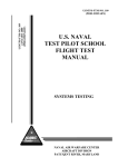
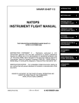
immediately apparent. Continue trimming until control is regained. POINT A.
POINT B.
PATH CD.
POINT D.
PATH CF.
Start takeoff roll with wing flaps down.
Takeoff point; start gear retraction.
Leave flaps down and climb out at 180 knots IAS to 1000 to 1500 feet above the terrain.
Start flap retraction at 1000 to 1500 feet altitude above the terrain.
Leave flaps extended and climb at unstick speed plus 10 knots until the obstacle is dented.
© 2010 Captain Sim www.captainsim.com
‘B-52 Driver’ FLIGHT MANUAL PART III – Normal Procedures
DO NOT USE FOR FLIGHT
POINT F.
PATH FG.
POINTS E
AND G.
19
Maximum desired altitude for clearing obstacle (at least 1000 feet above terrain).
Start flap retraction at 180 knots IAS; maintain sufficient rate of climb.
Points at wliich flaps are up. Accelerate to the best
Climb speed
NORMAL CLIMBOUT PROCEDURE
After unstick, the aircraft is accelerated to 180 knots IAS and a flaps down climbout made to at least 1000
feet above the terrain. At this point, flap retraction will be initiated. The aircraft will be accelerated on takeoff
heading during flap retraction whenever possible. The airspeed must be maintained above the minimum
recommended with flaps up.
OBSTACLE CLEARANCE CLIMBOUT PROCEDURE
When obstacles near the field must be cleared on takeoff, the climbout performance becomes very
important. A high angle of climb for clearing close obstacles is maintained by leaving the flaps down and
climbing at 10 knots above unstick speed until obstacle is cleared.
FLAP RETRACTION PRECAUTIONS
During flap retraction, the speed schedule should be maintained within ±10 knots.
This schedule gives a safe margin between flap placard and minimum speeds. If the airspeed is low, the
vertical velocity should be reduced or power added. During the flap retraction cycle, it is required that the
pilot monitor the aircraft attitude as closely as possible, keeping the aircraft trimmed to a zero stick force,
especially during the last 20' of flap retraction. If the climbout has been properly planned and no emergency
develops, a satisfactory vertical velocity can be maintained while accelerating during flap retraction.
However, under conditions of high gross weight, high OAT, and high field elevation, or any combination of
these factors, it may be impossible to maintain a positive vertical velocity during the latter part of the flap
retraction period. Flaps should not be retracted in a turn, and the speed schedule of 180 knots IAS at 100 %
flaps down, 200 knots IAS - flaps 50%, 210 knots IAS - flaps 30', and 230 knots IAS - flaps full up should
be followed. In any event, maintain a sufficient positive vertical velocity to keep from exceeding the flap
placard speed of 225 knots IAS at the 50% position and 253 knots IAS at the 10% position.
WARNING
•
The OFF flag will not appear during every attitude indication failure. Therefore, it is
possible that malfunction of the attitude indicator portion of the attitude-director indicator
might be determined only by crosschecking it with the turn and slip indicator and the other
remaining flight instruments.
SUMMARY OF AFTER TAKEOFF PROCEDURES
Climb out with flaps full down at 180 knots IAS to an altitude of at least 1000 feet above the terrain and
retract the flaps. If a positive vertical velocity of 1000 fpm is not attained when reaching 1000 feet above
the terrain, flap retraction will be delayed until an altitude of 1500 feet above the terrain is reached. If an
© 2010 Captain Sim www.captainsim.com
‘B-52 Driver’ FLIGHT MANUAL PART III – Normal Procedures
DO NOT USE FOR FLIGHT
20
obstacle must be cleared, climb out with flaps down at unstick speed plus 10 knots until a safe altitude has
been reached.
© 2010 Captain Sim www.captainsim.com
‘B-52 Driver’ FLIGHT MANUAL PART III – Normal Procedures
DO NOT USE FOR FLIGHT
21
AFTER TAKEOFF - CLIMB CHECKLIST
1.
Landing Gear Lever
GEAR UP, six up
CAUTION
If any gear fails to indicate up and locked, to prevent system damage, do not recycle the landing gear
system prior to initiating emergency procedure.
2.
Flap Lever
UP
At 180 knots IAS and a minimum altitude of 1000 feet above the terrain, the pilot directs the pilot to raise
the flaps. If a positive vertical velocity of 1000 fpm is not attained when reaching 1000 feet above the
terrain, flap retraction will be delayed until an altitude of 1500 feet above the terrain is reached. At the
appropriate time, the pilot advises, "Flaps coming up, flaps 50%, flaps 30%, and flaps full up. " In addition,
the pilot monitors the flight instruments, including the airspeed, during flap retraction. As a guide, the
normal speed schedule during flap retraction should be approximately 180 knots IAS at 100%, 200 knots
IAS at 50%, 210 knots IAS at 30%, and 230 knots IAS when flaps reach the full up position. If the actual
indicated airspeed varies from these values by 10 knots or more, the pilot should so advise the pilot so he
can make necessary pitch changes.
3.
Throttles
4.
Fuel Panel
5.
Altimeter
Pilot and pilot will periodically cross-check altimeter readings
Set
Checked
Set 29.92
in flight.
CLIMB
NRT will normally be used for climb. If climbs are made at less than normal rated thrust, a loss of range will
result because of the excessive time spent in climbing. MRT may be used for emergency conditions or as
mission requirements dictate. A point on the cruise flight path will be reached at approximately the same
time regardless of whether military rated thrust or normal rated thrust is used for the climb. Less fuel will be
required when military rated thrust is used, but engine life probably will be shortened slightly since higher
engine speeds and higher temperatures will be encountered.
CRUISE
With the engines stabilized at cruise flight condition, the pilot should monitor the oil temperature of each
engine at convenient intervals and observe any significant temperature variations between engines.
RANGE
Normally, a combat mission will be flown using procedures which will produce maximum range. The
performance of a jet aircraft is such that maximum range is attained by flying at one particular Mach number
and gradually increasing altitude as aircraft weight is decreased through fuel consumption. The rate of climb
required is very small (averaging from 16 to 20 feet per minute or about 1000 to 1200 feet per hour).
Therefore, rather than attempt to fly at some specified rate of climb, check the flight altitude with that given
in the altitude curve at frequent intervals (not to exceed 30 minutes) to assure that the proper climbing
flight path is being maintained. The autopilot altitude hold position may be used until the airspeed increases,
at which time a shallow climb should be initiated to place the aircraft at the correct altitude for the decreased
weight. This step climb procedure will be repeated as necessary The cruise True Mach number should be
checked frequently by means of the airspeed indicator. The machmeter may be inaccurate, causing a range
loss of several percent. There is only one weight-altitude schedule which will result in maximum range. Best
range (constant altitude) cruise is usually used for a noncombat mission because the difference in range
between this type of cruise and maximum cruise is not great if the altitude is above 35.000 feet.
© 2010 Captain Sim www.captainsim.com
‘B-52 Driver’ FLIGHT MANUAL PART III – Normal Procedures
DO NOT USE FOR FLIGHT
22
LOW ALTITUDE TACTIC
Penetration airspeed to the low altitude entry point will normally be 280 K2AS, unless aircraft restrictions
apply or using commands direct otherwise.
OPERATION
Present low altitude operational information is based upon the results of low altitude flight tests. During
these tests, the aircraft and its systems were operated at near maximum design capability. With the
requirement of all-weather flying at airspeeds up to the design limit of the aircraft, adequate preflight
planning is especially essential to successful completion of a low altitude mission. Icing conditions at low
altitudes and high speeds can be more severe than those normally encountered. Also, it is extremely difficult
to anticipate icing conditions during low altitude operation, particularly at night. Crew coordination is
considered critical when flying at low altitude. There have been some unusual psychological effects on crew
members and fatigue is found to increase much more rapidly at low altitude than at high. There is
considerable difficulty for pilots in interpreting readings of certain instruments while bouncing due to
turbulence; however, it is fairly easy to determine the range of scale which the instrument needle is in, and
generally, this is sufficient. Adverse effects which are frequently encountered at low altitude and which must
be considered when planning a mission are increased turbulence, reduced vision, reduced radar range, the
inconsistency of winds due to terrain effect, and extreme difficulty in the use of celestial navigation because
of turbulence and the frequency of overcasts.
LOW LEVEL DESCENT CHECKLIST
NOTE
•
The pilot should be alert for the condition of forward throttle creep from IDLE
position throughout descent to preclude unscheduled power resulting from advanced
throttle settings.
1.
Altimeter Settings
Obtain updated forecast altimeter settings values from a designated station.
Obtained
2.
EVS Power Switches
ON
3.
Terrain Display Mode Selector Switch
AS REQUIRED
4.
Anti-Icing Panel
Climatic
5.
Taxi Lights
ON
On training missions turn taxi lights on during night or day operations unless reflection reduces pilot
visibility.
6.
Altimeters
Set
Set altimeters to station pressure immediately prior to initiating penetration or upon passing through
transition altitude.
7.
8.
Autopilot
Radar & Pressure Altimeters
Disengaged
Cross-checked
CLIMB AFTER LOW LEVEL CHECKLIST
After completion of low level tactic when climbing back to altitude, perform the items in the "Climb After Low
Level" checklist.
•
NOTE
This check will be accomplished prior to descent to low level.
•
This check will be accomplished after a 1-minute warmup period of the terrain
computer.
1.
2.
3.
4.
5.
Throttles
Terrain Display Mode Selector Switch
Altimeter
Level-Off Check
Taxi Lights
© 2010 Captain Sim www.captainsim.com
Set
OFF
Set 29.92
Completed
OFF
‘B-52 Driver’ FLIGHT MANUAL PART III – Normal Procedures
DO NOT USE FOR FLIGHT
© 2010 Captain Sim www.captainsim.com
23
‘B-52 Driver’ FLIGHT MANUAL PART III – Normal Procedures
DO NOT USE FOR FLIGHT
24
DESCENT
The following procedures are for all letdowns where there is no range emergency and should be
accomplished as follows:
•
WARNING
Care should be taken to retrim between each 2-unit increment of airbrake operation.
NORMAL DESCENT
1.
Maintain cruising altitude until reaching the computed distance from the landing base. This distance
will depend upon aircraft altitude and weight at the end of mission.
2.
Lower the landing gear and retard all throttles to the IDLE stops. Observe the gear extension limits.
3.
Extend airbrakes to position 4 or as required.
4.
Make descent at 240 KIAS or Mach .75, whichever is slower.
•
fpm.
NOTE
Rate of descent may be varied (by airbrake position) but does not exceed 6000
ENROUTE DESCENT
1.
Throttles idle, gear up. and airbrake as necessary to provide desired airspeed and rate of descent to
comply with АТС requirements for the particular enroute descent.
2.
The many variables of an enroute descent will prevent precise calculations of range-time-fuel
performance.
TACTICAL DESCENT
Assuming the descent will start from cruise altitude and airspeed, the initial task is to retard the throttles to
idle and establish a nosedown attitude of approximately 10°. Extend airbrakes to position 6 in increments of
2, trimming to approximate zero stick force prior to raising the airbrakes to the next position. Maintain
approximately zero stick force by continually trimming the aircraft during descent. Maintain approximately
10° nosedown attitude and a speed schedule of . 84 Mach until reaching 305 KIAS. Maintain 305 KIAS during
the remainder of the descent. Close coordination between the pilot and pilot is required to insure that a
transition is made from indicated mach to indicated airspeed. Pilot will coordinate with the navigator as to
level-off altitude to be used for this maneuver. Initiate level off approximately 1000 feet above the desired
level flight altitude by retracting airbrakes from position 6, to position 4. to position 2. and retrimming.
Complete airbrake retraction at approximately 500 feet above the desired level flight altitude, retrim, and
add power as required.
NOTE
•
If turbulence is encountered such that the airspeed indicators are hard to read,
hold a 10° nosedown attitude until the turbulence has been penetrated. Aircraft attitude
should not exceed 12° nosedown.
DESCENT AND LANDING CHECKLIST
1.
EVS
ON
2.
Penetration & Approach
Reviewed
Obtain approach, landing weather, compare forecast versus reported altimeter setting, and review the
planned penetration and approach. This review will include navigation aid frequencies, minimum and
emergency safe altitudes, descent rates, minimums for the approach to be flown, missed approach
procedures, and aerodrome sketch. As a minimum the pilot flying the approach will brief the crew on the
descent rate, MDA/DH/VDP and missed approach procedures for the planned approach. Lost communications
procedures will be coordinated if required. During the descent and approach other crewmembers will back up
the pilot flying and report any deviation from prescribed procedures.
© 2010 Captain Sim www.captainsim.com
‘B-52 Driver’ FLIGHT MANUAL PART III – Normal Procedures
DO NOT USE FOR FLIGHT
25
3.
Landing Data
Computed and checked
4.
Nav Mode Select Switch
VOR/TACAN
5.
Fuel Panel
Checked
6.
Anti-Icing Switches
Climatic
7.
Lights
ON
Turn landing, taxi, and crosswind landing lights on for night or day operations unless reflection reduces pilot
visibility.
8.
Autopilot
Disengaged
Autopilot will be disengaged for penetration.
9.
Altimeter
Set
Reset altimeters to station pressure immediately prior to initiating penetration or upon passing through
transition altitude.
10.
Landing Gear
DOWN (if required), six down
The landing gear may be lowered at the pilot's discretion during an enroute descent or a published
penetration depending upon the rate of descent required. Pilot moves landing gear lever to GEAR DOWN and
checks for positive engagement of the pawl in the gear down detent by forcibly and positively pushing in on
the landing gear handle after the handle is in GEAR DOWN. Pilot checks operation of the landing gear
warning light. Both pilots check that the warning light is out, and that all six gears indicate down and locked.
CAUTION
•
To prevent system damage, if any gear fails to indicate down and locked, do not
recycle the landing gear system prior to initiating emergency procedure.
11.
Throttles
Set
NOTE
•
The pilot should be alert for the condition of forward throttle creep from IDLE
position throughout descent to preclude unscheduled power resulting from advanced
throttle settings.
•
To reduce engine compressor stalls, anti-icing should be turned off when making
an engine deceleration above 15, 000 feet. Anti-icing can then be turned on after the
engines have stabilized at the reduced throttle settings.
12.
Airbrakes
Set
The airbrake lever will normally be set at position 4; however, airbrakes may be used as required.
13.
Wing Flaps
100%
Allow aircraft to decelerate to 220 knots IAS. Pilot extends flaps at the request of the pilot and monitors flap
indicator to ascertain both flaps are extending simultaneously. Pilot reports when the flaps are 50% and full
down. Flap lever will be left in DN position. Flap extension time is 60 seconds. Flaps may be extended during
the penetration descent as required.
14.
Fuel Panel Switches
Checked
15.
Best Flare Speed
Rechecked
Best flare speed for airbrake position 4 is approximately 15 knots above the minimum touchdown speed.
Minimum touchdown speed is the same value as unstick speed and provides a 7 to 12 knot margin above
initial stall buffet speed.
16.
Landing Gear
Down, six down
17.
Crosswind Crab
Set, checked
Obtain wind direction and velocity. Compute and set crosswind crab as required. If crosswind crab is not to
be used, knob and position indicator must be checked for zero setting and gear position. Pilot checks
crosswind crab position indicator for the proper setting.
© 2010 Captain Sim www.captainsim.com
‘B-52 Driver’ FLIGHT MANUAL PART III – Normal Procedures
DO NOT USE FOR FLIGHT
26
18.
Target Trim
Noted
When aircraft is established on final approach in landing configuration (landing gear and flaps down and
airbrakes in planned position) at best flare speed plus 10 KIAS, pilot not flying the aircraft will note the
stabilizer trim setting for zero stick force. He will call out this value as target trim during an approach with
airbrakes in position 0 or 2. For an approach with airbrakes in position 4 or 6, he will compute a trim value
two units in the noseup direction from that noted and call out this computed value as target trim.
NOTE
•
It is preferable to note stabilizer trim while in straight and level flight. In VFR
traffic patterns or situations where it is not readily feasible to establish straight and level
on final approach, the stabilizer trim target setting during descent may be used provided
rate of descent does not exceed 1000 feet per minute.
19.
Landing
a.
b.
c.
d.
A check
Check
Gear
Flaps
Airbrakes 4 or as required
Lights
of the above items will be made when on final.
Completed
BEFORE LANDING
The before landing procedures are given in the "Descent and landing" checklist.
APPROACH
Since conditions at airports are continually changing, the landing approach techniques must be varied to
meet existing conditions. In general, a normal landing pattern can be used. With full airbrakes, the gliding
angle is approximately the same as that for a propeller-driven aircraft.
© 2010 Captain Sim www.captainsim.com
‘B-52 Driver’ FLIGHT MANUAL PART III – Normal Procedures
DO NOT USE FOR FLIGHT
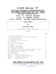
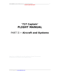
APPROACH PROCEDURE (VISUAL PATTERN)
© 2010 Captain Sim www.captainsim.com
27
‘B-52 Driver’ FLIGHT MANUAL PART III – Normal Procedures
DO NOT USE FOR FLIGHT
28
Referring to the figure, the downwind leg is entered at the altitude specified in applicable regulations. The
"Descent and Landing Checklist" will be completed at this point and the airspeed reduced to 30 knots above
computed best flare speed. The turn from the downwind leg will be a descending 90° turn to the base leg
with a reduction In airspeed and altitude. Roll out to a wings-level attitude while descending on the base leg
for sufficient duration (approximately 10 seconds) to allow for visual clearance of other aircraft in all
directions. Maintain 20 knots above computed best flare speed until starting turn to final approach. A 90°
descending turn to final approach will then be initiated and, at the completion of rollout on final approach,
the airspeed will be 10 knots above computed best flare speed, minimum altitude as specified in applicable
directives. A 30° bank will be the maximum allowable in the traffic pattern. The 10 knots above best flare
speed will be maintained until the flare point is reached. As the flare point is reached and the aircraft is
© 2010 Captain Sim www.captainsim.com
‘B-52 Driver’ FLIGHT MANUAL PART III – Normal Procedures
DO NOT USE FOR FLIGHT
29
rotated for landing, the throttles will be retarded so as to cross the end of the landing runway at best flare
speed. After touchdown, the airbrakes should be fully extended and the drag chute deployed.
NOTE
•
The pilot should be alert for the condition of forward throttle creep from IDLE
position throughout approach and landing to preclude unscheduled power resulting from
advanced throttle settings.
•
If a crosswind leg is flown, the aircraft will be rolled out to a wings-level attitude
on the crosswind leg for sufficient duration to permit visual clearance of other aircraft in all
directions.
•
The pilot's and/or pilot's sliding window may be opened at normal traffic pattern
speeds and maneuvers provided all hatches are in place. If a hatch has been released, the
opening of a sliding window should be avoided as inward acting airloads may cause the
window to blow into the cabin area.
© 2010 Captain Sim www.captainsim.com
‘B-52 Driver’ FLIGHT MANUAL PART III – Normal Procedures
DO NOT USE FOR FLIGHT
30
MINIMUM SPEEDS
The minimum recommended airspeeds at which the aircraft should be flown in straight flight with flaps either
up or down are given in the figure. It must be remembered that in turns the minimum speeds must be
increased from those shown.
© 2010 Captain Sim www.captainsim.com
‘B-52 Driver’ FLIGHT MANUAL PART III – Normal Procedures
DO NOT USE FOR FLIGHT
31
LANDING
LANDING WITH GUSTY WIND CONDITIONS
It is not necessary to increase the final approach speed for gust velocities up to and including 15 knots. For
gust velocities in excess of 15 knots, the final approach speed should be increased two-thirds of the gust
velocity in excess of 15 knots. For example, with a wind velocity of 20 knots with gusts to 50 knots, 10 knots
would be added to the final approach speed (total gust velocity 30 knots; 30 - 15 = 15 knots; 15 x 2/3 - 10
knots).
TOUCHDOWN
The recommended touchdown is with the rear gear first at minimum touchdown speed. Refer to Part 8 of the
Appendix for landing speeds. This allows for an adequate flare without a bounce. However, if the forward
gear is too high when the rear gear touches, a hard landing may result. Full airbrakes should be applied
immediately after touchdown provided there is no bounce. With the antiskid system operative, the wheel
brakes may also be applied immediately after touchdown although this decreases brake service life. The
runway available will determine when the wheel brakes should be applied.
•
NOTE
The front gear is well forward of the CG and if allowed to touch down first, a bounce is
almost certain to occur. This usually is the result, of too much speed.
NOTE
•
Sustained runway wind velocity plus one-third of the gust factor will be used to
compute crosswind crab settings when landing with gusty wind conditions.
•
If a crosswind cannot be compensated for by use of the crosswind crab system, a
landing is not recommended.
•
used.
If the wind is a variable wind, the average heading of this variable wind should be
•
Prior to or during the time the aircraft is in the traffic pattern, a decision must be
made as to whether or not the crosswind crab system is to be used. After obtaining the
wind direction and velocity from the tower located at the field at which the landing is to be
made, compute the crab angle for the wind and landing gross weight.
© 2010 Captain Sim www.captainsim.com
‘B-52 Driver’ FLIGHT MANUAL PART III – Normal Procedures
DO NOT USE FOR FLIGHT
32
CROSSWIND LANDING
WITH USE OF CROSSWIND CRAB SYSTEM
Smooth landings can be made through use of the crosswind crab system even though crosswinds of high
velocity are encountered. Such landings also require additional effort from the pilot. Touching down the
aircraft in a crabbed attitude may seem strange the first few times such landings are tried, but this
technique is easily learned by the pilot.
CROSSWIND CRAB SETTING. After voice radio contact has been established with the tower, obtain the
runway surface wind and direction. The most accurate wind measurements are obtained close to the ground.
Limited experience indicates that 50% of tower values closely approximate runway winds. If only
uncorrected tower wind values are used, it is recommended that the crab setting be established using 50%
of tower values. From this data, determine the crosswind crab setting to be used in landing. After the
landing gear has been extended, turn the crosswind crab control knob until the miniature aircraft and pointer
on the indicator point to the crab angle setting determined for the wind and gross weight. Extend the flaps,
raise airbrakes to position 4, and control the airspeed in the same manner as for a normal approach. After
rolling out onto final approach and after the aircraft is crabbed into the wind to establish a flight path
straight down the runway, recheck the position of the miniature aircraft and pointer on the crosswind crab
control indicator. The nose of the aircraft, as well as the nose of the miniature aircraft and pointer on the
indicator, should always be pointed off the runway into the direction of the wind component.
•
CAUTION
If rudder trim is used on landing, tie certain that the crosswind crab control knob
is not turned instead of the rudder trim knob since they are located concentrically.
LANDING ROLL. After the aircraft is on the runway, more and more lateral control will be required to hold
the wings level as the speed decreases. If difficulty is encountered in maintaining track down the runway at
low speeds, the control wheel should be centered since an asymmetric spoiler condition will cause an
unfavorable turning force. The crosswind crab system is not used to steer the aircraft on the ground.
NOTE
•
When landing under conditions of high crosswinds, light gross weights, and a
slippery runway, loss of steering may result.
© 2010 Captain Sim www.captainsim.com
‘B-52 Driver’ FLIGHT MANUAL PART III – Normal Procedures
DO NOT USE FOR FLIGHT
33
•
Be alert for indication of a missetting of crosswind crab at touchdown. Corrections
should be accomplished by normal rudder pedal steering. Do not use the crosswind crab
control knob for steering. On very smooth landings, a missetting of the crosswind crab will
not immediately manifest itself by the aircraft diverging off either side of the runway; the
first indication of incorrect setting will be a deceleration force due to tires scuffing.
WITHOUT USE OF CROSSWIND CRAB SYSTEM
If the crosswind crab system is not to be used because of a malfunction, the landing may be made by
approaching fully crabbed with rudder and lateral controls centered. If desired, a combination of crabbing
into the wind and a slight lowering of the upwind wing may be accomplished, but the wing should not be
lowered to such an extent that the tip gear touches the ground first upon landing. Touchdown in the crabbed
attitude with normal landing rates of descent will not induce detrimentally high side loads on the landing
gear since the gear is lightly loaded at this time. By landing rear gear first, the aircraft will tend to pivot
about the rear gear and thereby reduce the crab angle by the time the forward gear touches. Full airbrakes
should be applied and the drag chute may be deployed at touchdown since forward gear steering will be
adequate by the time the drag chute becomes effective.
MINIMUM RUN LANDING
The approach fur a minimum run landing should be planned so as to arrive over the end of the runway with
the throttles at IDLE and at a speed as close to best flare speed as possible. A minimum run landing is
accomplished by having the brake antiskid system operative, deploying the drag chute, using full airbrakes
after touchdown, applying wheel brakes immediately after touchdown, and continuing to apply brakes
throughout the landing roll. The drag chute provides considerable deceleration force over the first portion of
the landing roll while the wheel brakes have a small decelerating effect because the wheels are lightly
loaded. As the aircraft decelerates, the drag chute becomes less effective while the brakes become more
effective.
CAUTION
•
All landings should be planned from a landing distance standpoint as though the
drag chute were not installed. The chute should be considered only an aid to braking and a
means of reducing tire and brake wear.
WHEEL BRAKE APPLICATION
Each wheel is equipped with a complete brake antiskid assembly, eight units per aircraft. Therefore, when
one wheel approaches a skid and the brake pressure is released by the skid detector, no other wheel brake
assembly is affected. Regardless of this desired feature, however, the wings should be held as near level as
possible during the landing roll so that all wheels are on the ground. If the wings are not level, the high tire
on each landing gear becomes lightly loaded causing a loss in braking effectiveness because of the limited
braking torque on the heavily loaded wheels. Maximum braking effectiveness with antiskid operative is
obtained by depressing the rudder pedals fairly hard and letting the individual brakes cycle as required to
prevent skids. Application of a fairly hard force on the brake pedals will result in the heavily loaded wheels
being cycled at a slower and more desirable rate, while the lightly loaded wheels are cycled quite rapidly.
This cycling can be felt by the pilot and becomes quite noticeable, especially if several of the gears cycle on
and off at approximately the same time. If several of the gears do start to cycle in unison and cause a
violent vibration, the pedals should be released momentarily and then reapplied. The difference between
conventional braking and use of antiskid is that with antiskid operating, the brakes can be applied earlier in
the landing roll and maximum braking can be maintained throughout the entire roll without excessive tire
wear due to skids. On slippery surfaces at low taxi speeds, wheel deceleration is very fast when brakes are
applied and skid signals are generated more frequently, releasing brake pressure before a locked wheel
occurs. Aircraft deceleration is not felt by the pilots because of the fast cycling of the antiskid system.
However, the use of antiskid under these conditions is the recommended procedure since attempting to
brake without it results in greater stopping distances.
DRAG CHUTE DEPLOYMENT
Normally, the drag chute will be deployed on all landings. The drag chute should be deployed only after
touchdown. The time required for the drag chute to open is about 2 seconds after the drag chute lever is
pulled to DEPLOY position. It is not recommended that the drag chute be deployed during the flare while the
aircraft is floating since there is a tendency for the aircraft to pitch up or down, depending on the speed, and
to drop in due to rapid deceleration. See Section V for drag chute limitations.
© 2010 Captain Sim www.captainsim.com
‘B-52 Driver’ FLIGHT MANUAL PART III – Normal Procedures
DO NOT USE FOR FLIGHT
34
CAUTION
•
Dragging the chute along the runway causes considerable wear on the chute
suspension lines and canopy. If possible, keep engine maintain higher approach speed to
the flare thrust high enough at the lower ground run speeds to hold the chute off the
ground until the aircraft can be turned off the runway. Request the ground crew to stand
by to retrieve the chute as soon as the aircraft is clear of the runway and the chute is
jettisoned.
•
During prevailing surface winds of 15 knots or greater, do not turn more than 90°
away from the wind while drag chute is deployed.
NIGHT LANDING
The procedures and techniques used for a night landing are the same as those used for a normal day
landing. In addition, the terrain clearance light may be used at the pilot's discretion.
OBSTACLE CLEARANCE LANDING
If a relatively high altitude must be maintained to clear some obstacle located within the traffic pattern, a
steeper approach must be made after clearing the obstacle. A normal approach with full flaps and airbrake
lever in position 4 is made with sufficient altitude to clear the obstacle. If a steeper approach is desired,
airbrakes position 6 may be used. Should the obstacle be located close to the end of the runway, it may be
necessary to place the airbrake lever in position 6 and steepen the approach before passing over the
obstacle. In this case, the pilot should approach at a sufficiently high altitude to assure clearance with the
steeper approach. If full airbrakes are used, the rate of descent will be higher than normal and the flare will
have to be started earlier.
NOTE
•
If touchdown is to be made with full airbrakes, maintain higher approach speed to
the flare point.
LANDING CHECKLIST
Accomplish after touchdown (need not be read).
1.
Airbrake Lever
Position 6
2.
Drag Chute Lever
DEPLOY
Drag chute will be deployed on pilot's command. In the event a go-around is not anticipated and the drag
chute does not deploy, do not jettison the drag chute.
3.
Wheel Brakes
Checked
After establishing a stable ground roll, brakes will be checked for operation followed by intermittent
application of brakes as required.
4.
Hydraulic System
Check all hydraulic pumpout lights off.
Checked
5.
Centered
Crosswind Crab Control Knob
© 2010 Captain Sim www.captainsim.com
‘B-52 Driver’ FLIGHT MANUAL PART III – Normal Procedures
DO NOT USE FOR FLIGHT
35
GO-AROUND
The decision to make a go-around should be made as early as possible since engine acceleration time is a
factor and approach speeds are relatively close to touchdown speeds. Normally, this decision can be made
prior to touchdown. As soon as it has been decided to go-around, advance throttles to "go-around thrust"
which is the thrust required to arrest descent and produce a satisfactory rate of climb and/or acceleration,
retract airbrakes, trim as required, and, after it is certain that the aircraft will not touch the ground, retract
the landing gear. Further thrust refinements will be accomplished as necessary to obtain the desired
performance during the go-around.
WARNING
•
In cases where a go-around is initiated just prior to or during the landing flare and
where adequate runway is remaining, it may be necessary to maintain a touchdown
attitude, contact the runway, then retrim the aircraft during the ground run before
initiating power application for a go-around.
•
The thrust produced by the turbofan engines demands the use of proper
procedure and pilot technique when executing touch-and-go or go-around maneuvers. If
MRT is applied for touch and go or go-around below approximately 340, 000 pounds, the
aircraft will respond very rapidly. Immediate nose down trim will be required as a result of
1) any increase in airspeed, 2) the aft cg shift due to fuel movement to the rear of the
tanks in the case of partially full tanks, and 3) the nose up tendency produced by the
engine thrust line being below the cg. The adverse effect on aircraft trim is much more
pronounced at light gross weights. At light gross weights, nose down trim must be applied
simultaneously with any large increase in thrust to maintain positive control of the aircraft.
Conversely, any large decrease in thrust may be critical. If the aircraft has been allowed to
rotate to an extreme nose high attitude and is no longer accelerating at MRT, any attempt
to control the pitch by thrust reduction at this time will result in a stall. И the pitch attitude
has progressed to this point, the last resort for possible recovery is to maintain MRT for the
pushover and start retrimming as the airspeed begins to increase. It must be noted that
MRT is achieved short of full throttle and it is possible to obtain excessive overthrust if
throttles are advanced full forward.
•
The decision to go-around or land on the remaining runway must remain with the
pilot based upon all factors involved. However, if a situation is allowed to develop, which in
the pilot's judgement, requires a go-around from a low airspeed/low altitude condition, the
pilot must be extremely aware of the hazards of aircraft pitch up and the items affecting
pitch control. An unscheduled go-around with a mistrim condition can occur where several
other trim items occur simultaneously due to fuel shift, thrust, airbrakes, and ground
effect. Each item can be controlled by the use of elevator alone. But when several of these
items are combined the elevator, which is the primary flight control system, may not have
sufficient authority, and additional authority must be obtained from the stabilizer or
airbrakes. A 20 degree pitch attitude and strong buffet can easily occur in 3 seconds from
which a recovery may not be possible.
For pilot comfort and ease of flying, the thrust should be adjusted during climb to flap retraction altitude to a
setting which will produce a rate of climb not to exceed approximately 1000 feet per minute. If thrust has
been reduced during this initial climb, it may be necessary to add power during flap retraction to maintain
the desired speed schedule and to preclude loss of altitude. When the aircraft reaches 1000 feet and 180
knots IAS, the flaps may be retracted. However, if a positive vertical velocity of 1000 feet per minute is not
attained when reaching 1000 feet above the terrain, flap retraction will be delayed until an altitude of 1500
feet above the terrain is reached. During the flap retraction cycle, if is required that the pilot monitor his
aircraft attitude as closely as possible, keeping the aircraft trimmed to a zero stick force especially during the
last 20%.
WARNING
•
A go-around should not be attempted if the drag chute has been deployed since it
is possible that the drag chute may not jettison. Sufficient thrust is available from eight
engines to fly the aircraft with the drag chute deployed at weights below approximately
300, 000 pounds; however, this is not recommended since the associated control problems
have not be flight tested.
NOTE
•
When go-around is accomplished during closed traffic pattern work, the pilot may,
at his discretion, leave the landing gear and flaps down.
© 2010 Captain Sim www.captainsim.com
‘B-52 Driver’ FLIGHT MANUAL PART III – Normal Procedures
DO NOT USE FOR FLIGHT
36
NOTE
•
If a go-around is required under low altitude/low airspeed conditions pilots may
not have sufficient time to refer to the checklist. Therefore this checklist should be
accomplished as necessary and need not be read. When a safe altitude and airspeed is
attained the pilots will review the checklist and complete required items.
GO-AROUND CHECKLIST
1.
Go-Around Thrust
Set
The pilot will advance the throttles as required to arrest descent and produce a satisfactory rate of climb
and/or acceleration. Further thrust refinement will be accomplished as necessary to obtain desired
performance during the go-around. The throttle position should not exceed the thrust gate initially. The pilot
monitors the engine instruments and notifies the pilot of any abnormal engine operating characteristics.
•
•
WARNING
If the throttles are advanced beyond the thrust gate position for any reason, extreme care should
be exercised due to nose up rotation during acceleration.
If a go-around is initiated after starting landing flare, immediately counter the resultant pitching
moment with nose down elevator. Throttles will not be advanced beyond the thrust gate position
without simultaneously resetting the stabilizer toward target trim. Failure to retrim during the thrust
application phase of a go-around can result in pitch-up, which combined with other pitch trim items,
will exceed nose-down elevator authority. Also, with asymmetrical thrust, power must not be
applied faster than any generated roll-yaw problem can be controlled.
2.
Airbrake Lever
OFF
Pilot retracts airbrakes, levels off, and checks for a positive increase of airspeed.
3.
Trim
As required
At all times during go-around, pilot makes a conscious effort to keep the aircraft trimmed to zero stick force.
4.
Landing Gear Lever
As required
Pilot retracts the gear when it is established that aircraft will not contact the runway.
5.
Thrust
Adjusted
Pilot accelerates to desired IAS (best flare speed plus 30 KIAS or 180 KIAS) and adjusts thrust to establish a
rate of climb of approximately 1000 fpm.
6.
Wing Flaps
As required
Flaps will be retracted in a wings level attitude, using the normal speed schedule and in accordance with the
flap retraction procedures outlined in the "After Takeoff-Climb Checklist," this section. If the flaps are raised
to accomplish flaps up training, or if the pilots' intentions are to remain in the aircraft traffic area/terminal
control area, accelerate to approach speed plus 30 KIAS.
•
NOTE
Accomplish "After Takeoff - Climb" or Traffic Pattern" checklist, as applicable.
TOUCH-AND-GO LANDING
Failure to lower airbrakes and retrim the aircraft to target will result in excessive nose up rotation
immediately following unstick. The large amount of thrust available from the turbofan engines makes the
use of partial thrust procedures for touch and go of the utmost importance to preclude a possible hazard due
to the rapid acceleration. The thrust gate is used to provide a satisfactory partial thrust level for touch-andgo landings. Rapid pitch changes must be countered immediately by continuous use of stabilizer trim in
addition to control column movement. Touch-and-go landings can normally be performed within the limits
shown in the amplified "Touch-and-Go Landing" checklist unless additionally restricted by the major
command concerned.
© 2010 Captain Sim www.captainsim.com
‘B-52 Driver’ FLIGHT MANUAL PART III – Normal Procedures
DO NOT USE FOR FLIGHT
37
TOUCH-AND-GO LANDING CHECKLIST
NOTE
•
This checklist will be reviewed prior to touch-and-go landings and need not be
read while on the runway.
1.
2.
Airbrake Lever
Stabilizer Trim
Position 6
Reset
WARNING
•
If the stabilizer trim is not reset prior to takeoff, the excessive amount of nose up
trim will cause a nose up rotation after takeoff. Any pitch attitude changes following a
takeoff will be countered immediately by continuous use of the stabilizer trim in addition to
control column movement.
NOTE
•
The operation of the stabilizer trim mechanism during the ground roll of touchand-go landings is considered to be an inflight procedure and inflight operation limitations
will apply.
3.
Airbrake Lever
OFF
It is essential that the airbrake lever be returned to OFF before executing the takeoff following a touch-andgo to preclude an unexpected pitchup following takeoff.
4.
Throttles
Advance
The pilot performing the takeoff after a touch-and-go landing will advance the throttles slowly to an
intermediate setting allowing engines to accelerate and stabilize prior to advancing the throttles to the thrust
gate. Do not advance throttles until the trim has been reset. The pilot will monitor the engine instruments.
Further thrust refinement will be accomplished as necessary to obtain the desired performance during
takeoff and climb. See "Go-Around, " this section, for thrust effects. Premature liftoff prior to unstick speed
(minimum touchdown speed) can be hazardous since there is only a 7 to 12 knot margin between unstick
speed and initial stall speed. Premature liftoff can only occur when stabilizer is mistrimmed and/or excessive
back column is introduced prior to unstick. Accelerate to best flare speed plus 30 KIAS on climbout.
•
NOTE
Accomplish "After Takeoff - Climb" or 'Traffic Pattern" checklist, as applicable.
TRAFFIC PATTERN CHECKLIS
1.
Airbrake Lever
As desired
Airbrakes may be used as desired until on final approach when they will normally be Position 4.
2.
Planned Approach
Reviewed (if applicable)
Check the appropriate navigation aids tuned. Altitude restrictions, descent rate, MDA/DH/VDP, and missed
approach procedures will be emphasized. Review if type approach/pilot changes.
4.
6.
7.
Wing Flaps
Best Flare Speed
Thrust
100%
Checked
Set
8.
Landing Gear
DOWN, six down
Pilot checks gear lever in detent. Both pilots check that the gear warning light is out and that all six gear
indicate down and locked.
9.
10.
11.
Crosswind Crab
Target Trim
Landing Check
a. Gear
b. Flaps
c. Airbrakes 4 or as required
d. Lights
e. Fuel
A check of the above items will be made when established on
© 2010 Captain Sim www.captainsim.com
Set, checked
Noted
Completed
final.
‘B-52 Driver’ FLIGHT MANUAL PART III – Normal Procedures
DO NOT USE FOR FLIGHT
38
TAXI-BACK LANDING
Full stop taxi-back landings may be accomplished under the following limitations:
1.
Airplane gross weight will not exceed 270.000 pounds.
2.
Touchdown will be accomplished in the first third of the existing runway to include the
sterile portion of the approach end.
3.
Planned landing ground run will not exceed 50% of the available runway exclusive of the
sterile portion of the approach end.
4.
After establishing a stable ground roll, brakes will be checked for operation followed by
intermittent application of brakes as required.
5.
A minimum interval of 15 minutes air time will be established between landings or prior to
retracting the gear to provide wheel and brake cooling.
6.
If the first taxi-back landing accomplished is:
a.
Above 250.000 pounds, a maximum of one full stop taxi-back landing may be
accomplished on each sortie, followed by a final full stop landing utilizing the drag chute,
b.
At or below 250.000 pounds, a maximum of four full stop taxi-back landings may
be accomplished on one sortie. The fourth landing may be followed by a final full stop
landing utilizing drag chute.
TAXI-BACK LANDING CHECKLIST
1.
Airbrakes
Position 6
2.
Drag Chute
Deploy (if required)
3.
Brakes
Checked
4.
Hydraulic System
Checked
5.
Crosswind Crab
Centered
8.
Drag Chute
JETTISON (if applicable)
9.
Brakes
Set
10.
Sliding Window
Open
11.
Stabilizer Trim
Set Checked for takeoff setting
12.
Airbrakes
OFF
13.
Flaps
100%, lever down
14.
Fuel Panel Switches
Check
15.
Takeoff Data
Reviewed
16.
Crew
Stand by for takeoff
17.
Lights
ON
Turn landing, taxi, and crosswind landing lights on for night or day operations unless reflection reduces pilot
visibility.
18.
19.
20.
21.
22.
Crosswind Crab
Takeoff Thrust
70 Knots
Stabilizer Trim
Unstick Speed (S2)
© 2010 Captain Sim www.captainsim.com
Set Checked
Set
Now
Monitor
Now
‘B-52 Driver’ FLIGHT MANUAL PART III – Normal Procedures
DO NOT USE FOR FLIGHT
39
AFTER LANDING
The after-landing check shall be performed after the aircraft has been turned off the runway. Hard taxi
braking or riding the brakes shall be avoided at all times, particularly after a landing or refused takeoff.
AFTER LANDING CHECKLIST
1.
Lights
OFF (if applicable)
Turn landing, taxi, and crosswind landing light switches OFF or as necessary for taxi operations.
2.
Drag Chute Lever
JETTISON
The drag chute will be jettisoned and the control handle returned to LOCKED by the pilot after the aircraft
has turned off the runway and prior to being stopped for completion of the "After Landing Checklist."
CAUTION
•
To prevent or minimize damage to aircraft structure as the drag chute disconnect
link strikes it during the jettison sequence, jettison the chute at the lowest taxi speed that
will keep the chute inflated.
3.
4.
5.
8.
9.
12.
13.
Parking Brakes
Set
Yaw Switch
DISENGAGE
Rudder/Elevator Hydraulic Switches
OFF
Airbrake Lever
OFF
Stabilizer Trim
Reset to zero
Starter Switches
OFF
Unnecessary Electrical Equipment:
b.
Mach Indicator Switch
OFF
c.
Pitot Heat Switches
OFF
d.
Windshield & Engine Anti-Icing Switches
OFF
f.
Autopilot Master Switch
OFF
15. Generators 1, 7
OFF
16. Throttles 1, 2, 7 , 8
75% rpm, then CLOSED
While taxiing back to the ramp, advance throttles 1, 2, 7, and 8 to approximately 75% rpm for not less than
15 nor more than 30 seconds before moving to the CLOSED position. This will insure complete scavenging of
engine oil and prevent overservicing. This procedure will also prevent fuel from accumulating underneath the
engines after shutdown. No. 5, 6 engines may also be shut down if necessary to reduce taxi speed and still
maintain sufficient electrical and hydraulic power for the aircraft.
17.
Fuel Panel
Close all fuel valves not required.
Checked
18.
Sliding Window
Open sliding window to relieve cabin pressure.
Open
19.
Bomb Door Switch (nuclear and training missions only) OPEN
If munitions are aboard or have been released, bomb doors will not be opened until after parking.
ENGINE SHUTDOWN
CAUTION
•
If an engine has been operating at above 85% rpm for a period exceeding 1
minute after landing, allow the engine to idle at least 5 minutes before shutting down. This
will prevent damage resulting from rapid temperature change.
•
Normally, an engine will be sufficiently cool after landing to permit an immediate
shut
© 2010 Captain Sim www.captainsim.com
‘B-52 Driver’ FLIGHT MANUAL PART III – Normal Procedures
DO NOT USE FOR FLIGHT
40
BEFORE LEAVING AIRCRAFT CHECKLIST
1.
Parking Brakes
2.
Anticollision & Navigation Lights
3.
EVS Power Switches
4.
Gyro Power Switch
5.
Bomb Door Switch
Bomb doors will be opened at this time if conventional internal munitions were
be on interphone and confirm that bomb doors are clear.
Set
OFF
OFF
OFF
OPEN
carried. Ground personnel will
WARNING
•
If conventional internal munitions were carried, the flight crew must visually check
bomb bay prior to opening bomb doors.
6.
Generators 3 & 5
OFF
7.
Throttles
75% rpm, then CLOSED
Before shutting down any engines, advance throttles to 75% rpm to accomplish scavenging. Sufficient
engine scavenging will be accomplished by not less than 15 nor more than 30 seconds of engine operation at
75% rpm. Move throttle to CLOSED within a few seconds after retarding throttle from the 75% setting.
8.
9.
10.
11.
12.
13.
Radios
Fuel Panel Switches
Oxygen System
Parking Brakes
Light Switches
Battery Switch
© 2010 Captain Sim www.captainsim.com
OFF
OFF or CLOSED
OFF
OFF
OFF or as required
OFF
‘B-52 Driver’ FLIGHT MANUAL PART III – Normal Procedures
DO NOT USE FOR FLIGHT
41
SECTION II
ALL WEATHER OPERATION
INSTRUMENT FLIGHT PROCEDURES
The procedures and techniques outlined in current instrument flying directives should be followed. Flight
characteristics during instrument conditions do not differ from those encountered during visual flight
conditions. Limit angle of bank to 30° for all normal instrument maneuvers.
INSTRUMENT TAKEOFF AND INITIAL CLIMB
An instrument takeoff is essentially the same as a normal VFR takeoff. The same procedures are used.
Ensure the attitude indicator is set for takeoff by aligning the horizon bar with the miniature aircraft.
1. Align the aircraft visually with the runway. The pilot will visually monitor the takeoff and initial climb. A
takeoff with reference to instruments exclusively may be required because of low visibility conditions.
NOTE
•
The bank steering bar will be used during the takeoff and climb as an aid in
heading control. Cross-checking of the bank steering bar, turn needle, and heading
indicator will provide indication of attitude indicator failure in the roll axis. If the roll axis of
the ADI is inoperative on takeoff, the bank steering bar will aid in maintaining a wings-level
attitude until a new heading is selected. This type of failure has occurred several times
without a warning flag in view. If a new heading is selected, then the roll axis failure should
become apparent as the turn is initiated. A rapidly precessing heading indicator will also
give the same indications.
•
As the aircraft breaks ground, maintain the unstick attitude as indicated by the
attitude indicator until a cross-check of vertical velocity indicator and altimeter indicate a
definite rate of climb with increasing airspeed.
WARNING
•
If a pitchup occurs as the aircraft becomes airborne, failure to initiate positive
action with the elevator control and trim to stop the aircraft nose up rotation could result in
a stall.
•
The OFF flag will not appear during every attitude indicator failure. Therefore, it is
possible that a malfunction of the attitude indicator might be determined only by crosschecking it with the turn and slip indicator and the other flight instruments.
NOTE
•
The ATT warning flag indicates the attitude information displayed on the pilot
and/or pilot attitude director indicator may be erroneous and the standby attitude indicator
should be checked to determine proper attitude references.
•
An error in the pitch indication of the attitude indicators is generated during
accelerations or decelerations. The error is Indicated in a nose high direction during and
after a forward acceleration and a nose down direction during and after deceleration. The
longer the duration of acceleration (or deceleration), the greater will be the indicated error
and the longer it will persist when acceleration (or deceleration) ceases. The erection
system will reduce the error at about the same rate as it was generated. Pitch error may
reach one bar width during a high gross weight takeoff.
3.
Retract the gear as recommended for a VFR takeoff; however, be certain that a safe stabilized climb
has been established. Adjust pitch as necessary to maintain a climb at 180 knots IAS.
4.
Retract flaps as recommended in for а VFR takeoff.
© 2010 Captain Sim www.captainsim.com
‘B-52 Driver’ FLIGHT MANUAL PART III – Normal Procedures
DO NOT USE FOR FLIGHT
42
INSTRUMENT CRUISE
The aircraft has satisfactory handling characteristics throughout the design airspeed and altitude range. Use
the recommended procedures for cruise operation.
•
NOTE
The rotating anti-collision lights should be turned off during actual instrument
flight conditions whenever the pilot can notice the rotating light reflections in the cockpit. A
pilot may experience vertigo from these reflections. In addition, the lights will be ineffective
during such instrument flight conditions.
HOLDING
Enter the holding pattern in accordance with procedures as outlined in current directives. Establish a holding
airspeed of 230 knots IAS for all altitudes from 15. 000 to 35, 000 feet and for all gross weights up to 325.
000 pounds. Maintain the airspeed 10 knots above that given or Mach . 77, whichever is less, for endurance
at the given weight to allow for holding turns.
NOTE
•
If it is necessary to endure and fuel quantity is low, establish the holding airspeed
recommended for the existing gross weight and altitude. Increase the airspeed 10 knots or
maintain Mach .77, whichever is less. Maximum endurance altitude is recommended.
© 2010 Captain Sim www.captainsim.com
‘B-52 Driver’ FLIGHT MANUAL PART III – Normal Procedures
DO NOT USE FOR FLIGHT
43
TYPICAL DESCENTS AND PENETRATIONS
NOTE
•
Enroute descents are compatible with the typical penetration procedures except
for aircraft configuration, airspeed, rate of descent and routing to the final approach.
1. Prior to starting a penetration, initiate "Descent and Landing Checklist."
2. A normal penetration is accomplished with the gear down, throttles idle, airbrakes position 4 or as
required at 240 knots IAS or . 75 Mach, whichever is slower.
WARNING
•
Care should be taken to retrim between each two-unit increment of airbrake
operation.
© 2010 Captain Sim www.captainsim.com
‘B-52 Driver’ FLIGHT MANUAL PART III – Normal Procedures
DO NOT USE FOR FLIGHT
44
NOTE
•
Rate of descent may be varied (by airbrake and/or throttle position) to satisfy
local penetration procedures.
3.
Conform to published procedures.
4.
Pilot obtains altimeter setting prior to descent and set altimeters at the prescribed time during
descent.
5.
Retract airbrakes as required. Allow the aircraft to decelerate to 220 knots IAS. Complete the
"Descent and Landing Checklist" as required. Establish best flare speed plus 30 knots. Reduce airspeed to
best flare plus 10 knots prior to the final approach fix or glide slope interception. Maintain best flare plus 10
knots until the flare for landing is started. If visual references at the missed approached point are insufficient
to land, execute the missed approach procedure.
© 2010 Captain Sim www.captainsim.com
‘B-52 Driver’ FLIGHT MANUAL PART III – Normal Procedures
DO NOT USE FOR FLIGHT
INSTRUMENT APPROACHES
This aircraft and all modified versions thereof are in approach category "E."
RADAR APPROACH
© 2010 Captain Sim www.captainsim.com
45
‘B-52 Driver’ FLIGHT MANUAL PART III – Normal Procedures
DO NOT USE FOR FLIGHT
46
Entry into the radar approach pattern is normally made with gear down at 220 knots IAS. Complete
"Descent and Landing Checklist'. Adjust power to maintain best flare speed plus 30 knots IAS alter the flaps
are down. Reduce airspeed to best flare plus 20 knots on base leg. After the turn to final approach and prior
to reaching the glide slope, reduce airspeed to best flare plus 10 knots IAS. Maintain best flare plus 10 knots
until the flare for landing is started. When the minimum altitude is reached as indicated by the altimeter or
when advised by the controller, whichever occurs first, perform the missed approach procedure if visual
references are inadequate for landing.
© 2010 Captain Sim www.captainsim.com
‘B-52 Driver’ FLIGHT MANUAL PART III – Normal Procedures
DO NOT USE FOR FLIGHT
47
AUTOMATIC ILS APPROACH
The aircraft is equipped with an approach coupler which permits automatic ILS approaches. Except for the
use of the autopilot and approach coupler, the following procedures also apply to manual approaches.
© 2010 Captain Sim www.captainsim.com
‘B-52 Driver’ FLIGHT MANUAL PART III – Normal Procedures
DO NOT USE FOR FLIGHT
48
TRANSITION TO FINAL
Accomplish a normal transition as specified in the terminal charts. Set the NAV mode select switch to ILS,
tune the ILS frequency, set the inbound localizer course in the course selector window. Complete the
"Descent and Landing Checklist" and established best flare plus 30 knots IAS. Engage the autopilot and turn
altitude control switch ON when at glide slope interception altitude. When the aircraft is within 90' of the
inbound course, decelerate to best flare plus 20 knots IAS and center the bank steering bar. This will initially
establish up to a 45° intercept to the localizer. As the aircraft approaches the localizer, the bank steering bar
will direct a turn on course. When the aircraft is on the localizer course inbound (CDI centered), engage the
autopilot localizer placing the nav mode select switch to ILS. Stabilize the aircraft at best flare plus 10 knots
IAS prior to the glide slope interception point. Eliminate localizer standoff by use of the roll trim knob.
© 2010 Captain Sim www.captainsim.com
‘B-52 Driver’ FLIGHT MANUAL PART III – Normal Procedures
DO NOT USE FOR FLIGHT
49
FINAL APPROACH
When the glide slope indicator reaches center, engage the glide slope placing the nav mode select switch to
ILS APP and adjust power to maintain best flare plus 10 knots IAS. For a manual approach, keeping the
bank steering bar centered will automatically correct for wind, and keeping the pitch steering bar centered
will establish the pitch attitude necessary to correct to or maintain the glide slope. Continue the approach
until visual references are sufficient to land or to published minimums, whichever is higher. At this point, disengage the autopilot to land or to follow the missed approach procedures. Check trim indicators prior to
disengaging autopilot.
WARNING
•
During an ILS final approach using the Flight Director System (ILS APP mode
selected) the loss, or reduction in strength, of the glide slope signal will normally cause the
glide slope warning flag to appear. Simultaneously with the warning flag appearance, the
glide slope indicator and pitch steering bar may remain at or slowly move toward a
centered position. Failure to immediately observe the (red) warning flag under conditions
requiring high instrument (red) lighting intensities, coupled with the false "on glide slope"
indication, could result in misinterpretation by the pilot. During the ILS final approach
phase a frequent cross-check should be made for the glide slope warning flag and/ or
unduly stabilized glide slope indicator/ pitch steering bar combination. A continuous crosscheck of altitude and rate of descent should be made as well as monitoring marker
beacons, aural signals and radar altimeters, whenever possible.
CIRCLING APPROACH
Generalized procedures for circling approaches are contained in current instrument flight directives. Follow
enroute descent or jet penetration procedures; however, reduce airspeed to best flare plus twenty knots
prior to the final approach fix. Maintain twenty knots above best flare speed during the circling maneuver
until beginning rollout to align with the landing runway. At that time, reduce to best flare speed plus ten
knots until the landing flare point is reached. Bank angle should be limited to thirty degrees throughout the
maneuver.
MISSED APPROACH
Missed approaches are accomplished using the same procedures as for VFR go-arounds. Advance throttles
as required, retract airbrakes, establish a positive climb (approximately 1000 feet per minute is appropriate
for most missed approaches), trim as required, and check for a positive increase in airspeed. Aircraft
acceleration upon executing the missed approach procedure is such that at light weights under instrument
conditions flap placard speeds may be rather quickly exceeded.
WARNING
•
Care should be exercised in applying power at light gross weights due to pitchup
developing during acceleration.
Retract gear as soon as it is certain that the aircraft will not touch the ground and retract flaps as specified
if the published missed approach procedure is to be followed or if proceeding to an alternate airport. During
the flap retraction cycle, it is required that the pilot monitor the aircraft attitude indications as closely as
possible, keeping the aircraft trimmed to a zero stick force, especially during the last 20% of flap retraction.
NOTE
•
If a closed radar approach pattern is to be made, the pilot may, at his discretion,
leave the gear and flaps down and maintain airspeeds as specified for a normal radar
approach pattern.
© 2010 Captain Sim www.captainsim.com
‘B-52 Driver’ FLIGHT MANUAL PART III – Normal Procedures
DO NOT USE FOR FLIGHT
50
CUSTOMER CARE
FORUM
You are invited to join Captain Sim community forum
DAILY NEWS
For Captain Sim daily news please follow us at Twitter or Facebook.
VIDEO CHANNEL
For Captain Sim videos please watch our YouTube channel.
TECH SUPPORT
The 'B-52 Driver' is the most advanced, complete and accurate digital replica of the B-52 aircraft ever available for any game platform.
Our product is not perfect (unfortunately nothing is). But we are working on improvements. If you have
some important issue to report, please check-in to Your Profile then click Product Name > Customer Support
> and use the Trouble Ticket System. We process all tickets and consider the most significant issues for the
next service packs.
© 2010 Captain Sim www.captainsim.com