1
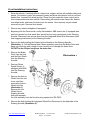
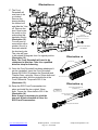
Illustration 14
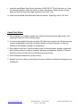
Use Original Hardware
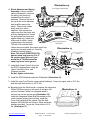
30. Shock Absorber and Spring
Assembly. Using a suitable
spring compressor, compress
the spring until tension is
released from the shock
absorber. Remove the nut at
the top of the shock absorber
and carefully remove the
shock. Remove the rubber
Area to Grind
bump stop from shock
absorber. Now remove the
striker cap from the shock and
slide the spring seat off. Install
the spring seat on new shock
against snap ring. Install new
striker cap on shock. Install
Front Crossmember
original bump stop on shaft.
20-52404-1
This will fit around the black
rubber sleeve provided. Now insert shock into
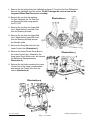
Illustration 15
spring and cap and install nut. Carefully
release the spring tension.
Front Crossmember
FRONT OF
20-52404-1
VEHICLE
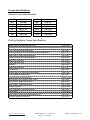
Note: The shock (50-BE5-B316-T0)
has two snap ring grooves. For 6”
lift use the upper groove. If you
would like 4” lift then move the
snap ring to the lower groove.
31. Install both Lower Control Arms into
the RCD Crossmembers using the
18mm Cam Bolts, Nuts, and
Washers provided.
Do Not tighten at this time.
Skidplate
20-52404-4
Rear Crossmember
20-52404-2
3/8" x 1-1/2" Bolts,
Washers, & Nuts
32. Install the RCD Skidplate under the Differential. (Illustration 15).
33. Install the new Front Shocks using original hardware. Torque the upper nuts to 35 ft. lbs,
and the lower bolt and nut to 351 ft. lbs.
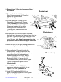
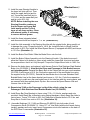
34. Beginning with the Driver’s side, compress the Integrated
Wheel End Disconnect on the bench to collapse the
vacuum chamber. While it is collapsed install a
vacuum cap on the vacuum port (Illustration 16).
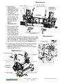
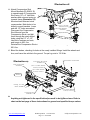
Install the Integrated Wheel End Disconnect on the
outer constant velocity joint housing. Install the
Front Axle Halfshaft in the vehicle. Use the Axle
Spacers 20-52404-20 and 12mm x 50mm bolts and
washers provided. Torque the 12mm bolts to 60 ft.
lbs. (Illustration 17).
www.racecardynamics.com
RCD Suspension 619-588-4723
Page 11 - #16-42404
Illustration 16
[email protected]