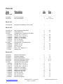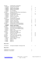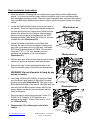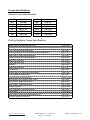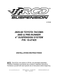
1
11/09/05
’04-’06 FORD F-150 4WD
4”-6” SUSPENSION SYSTEM
P/N: 10-42404
INSTALLATION INSTRUCTIONS
NOTE: Each lift kit, and options to lift kits, are packaged separately. Therefore
installation procedures are covered in separate instructions. Familiarize yourself
with each specific set of instructions before beginning.
www.racecardynamics.com
RCD Suspension 619-588-4723
Page 1 - #16-42404
[email protected]
Part List
Item
Description
Qty.
Illus.
Front Crossmember
Rear Crossmember
1
1
14, 15
10, 11, 15, 19
Steering Knuckle/Spindle - Driver's Side
1
1
Rear Compression Strut Mount
Compression Strut
Hardware Pack: Compression Strut Mount
Hex Bolt, 1/2" x 1-1/2" Gr. 8
Hex Bolt, 7/16" x 3-1/2" Gr. 8
Washer, 1/2" Flat HRDN
Washer, 7/16" Flat HRDN
Nut, 1/2" Top Lock
Nut, 7/16" Top Lock
Hardware Pack: Compression Strut
Hex Bolt, 1/2" x 4"
Washer, 1/2" Flat
Nut, 1/2" Nyloc
Sleeve, 3/4" x .095w x 2.75"
Bushing, Red
2
2
1
4
2
8
4
4
2
1
4
8
4
4
8
19
19
Rack and Pinion Bracket
Differential Skidplate
Sway Bar Drop Bracket
Differential Drop Bracket (Pass.)
Differential Drop Bracket (Drvr.)
Hardware Pack: Misc. Mounts
Hex Bolt, 5/8" x 4-1/2" Gr. 8
Hex Bolt, 7/16" x 1-1/4" Gr. 8
Hex Bolt, 3/8" x 1-1/2" Gr. 8
Washer, 5/8" Flat HRDN
Washer, 7/16" Flat HRDN
Washer, 3/8" Flat HRDN
Washer, 3/8" Split Lock
Nut, 5/8" Top Lock
Nut, 7/16" Top Lock
Nut, 3/8" Top Lock
Rack & Pinion Spacer
2
1
2
1
1
1
2
4
4
4
8
6
2
2
4
2
2
Box 1 of 6
20-52404-1
20-52404-2
Box 2 of 6
20-52404-5D
Box 3 of 6
20-52404-10
20-52404-11
20-70255
13-21456-Z
13-23120-Z
13-30382-Z
13-30304-Z
13-10514-Z
13-10384-Z
20-70268
13-20069-Z
13-30034-Z
13-10038-Z
20-830918
15-11148
19
10
19
10
19
10
19
19
19
19
19
Box 4 of 6
20-52404-3
20-52404-4
20-52404-7
20-52404-8
20-52404-9
20-70242
13-22028-Z
13-21118-Z
13-23471-Z
13-30369-Z
13-30304-Z
13-30408-Z
13-30151-Z
13-10345-Z
13-10384-Z
13-10553-Z
20-834350
www.racecardynamics.com
RCD Suspension 619-588-4723
Page 2 - #16-42404
8
15
18
9, 10
9, 10
8
18
15
8
18
15
15
8
18
15
8
[email protected]
20-70281
20-52404-14
13-23588-Z
13-30876-Z
13-30304-Z
13-10969-Z
13-10384-Z
20-70294
20-52404-12
20-52404-13
13-22093-Z
13-30304-Z
13-10384-Z
20-70512
20-52404-20
13-20758-Z
13-30460-Z
13-30546-Z
20-70525
20-52404-15
13-20758-Z
13-30546-Z
20-70564
50-52404-1
50-52404-2
50-5700-2
50-5700-4
20-68188
13-30330
13-10423
13-91049
20-834220
20-68305
13-20447-Z
15-10966
15-11395
15-11447
15-11460
Hardware Pack: Crossmembers
04-Up Ford F150 Cam Bolt
Hex Bolt, 7/16" x 4" Gr. 8
Washer, 18mm Flat HRDN
Washer, 7/16" Flat HRDN
Nut, 18mm Nyloc
Nut, 7/16" Top Lock
Hardware Pack: Rear E-Brake Cable & Brakeline
Rear Brakeline Mount
Emergency Brake Cable Mount
Hex Bolt, 7/16" x 1-1/2"
Washer, 7/16" Flat HRDN
Nut, 7/16" Top Lock
Hardware Pack: Axle Spacers
04-Up Ford F150 Axle Spacer
Hex Bolt, 12mm x 50mm
Washer, 12mm Split Lock
Washer, 12mm Flat HRDN
Hardware Pack: Front Driveshaft Spacer
04-Up ford F150 Front Driveshaft Spacer
Hex Bolt, 12mm x 50mm
Washer, 12mm Flat HRDN
Hardware Pack: Front Brakelines
04-Up Ford F150 Front Brakeline (Drvr.)
04-Up Ford F150 Front Brakeline (Pass.)
Brake Line Clip
Brake Line Crush Washer 10mm
Hardware Pack: U-Bolts
Washer, 9/16" Flat HRDN, Plain
Nut, 9/16" High, Plain
U-Bolt, 9/16" x 3-1/4" x 12.5" SQ
04-Up Ford F150 Rear Block (5in.)
Hardware Pack: Misc.
Screws for Brake Line Clamps
Brake Line Clamps
Zip Tie, 6"
Zip Tie, 8"
Zip Tie, 11"
1
4
1
4
2
4
1
1
1
1
1
2
1
1
2
12
12
12
1
1
4
4
1
1
1
2
4
1
8
8
4
2
1
4
4
4
2
2
Steering Knuckle/Spindle - Passenger's Side
1
10
10
10
21
20
17
17
17
17
13
13
13
22
22
22
22
Box 5 of 6
20-52404-6P
2
Box 6 of 6
50-BE5-B316-T0 Front Shock
50-BE5-B317-T0 Rear Shock
www.racecardynamics.com
2
2
RCD Suspension 619-588-4723
Page 3 - #16-42404
[email protected]
INTRODUCTION
•
Installation by a professional mechanic is recommended. Use of the appropriate tools, a
Ford service manual, and a shop hoist can greatly reduce installation time.
•
Prior to installation, carefully inspect the vehicle’s steering and drive train systems, paying
close attention to the tie-rod ends, rack & pinion unit, ball joints and wheel bearing
preload. Also check steering-to-frame and suspension-to-frame attachment points for
stress cracks. The overall vehicle must be in excellent working condition; repair or replace
worn parts.
•
Read instructions carefully and study illustrations before attempting installation. RCD
Suspension is not responsible for damage, failure or injury resulting from improper
installation or parts substitution of this kit.
•
Check parts and hardware against the parts list to assure that your kit is complete. Report
any shortages to RCD Suspension at (1-619-588-4723). The parts and hardware supplied
are of high-grade material and must not be replaced by inferior parts or failure may result.
Do not begin installation if parts are missing.
•
Separate parts according to the areas they will be used. Placing the hardware with
brackets before you begin will save installation time.
•
This kit is supplied as a bolt-on assembly. Do not weld anything to the components and
do not weld the components to the vehicle.
•
All components in this kit come with a protective coating. Do not plate (i.e. chrome,
cadmium, zinc etc.) or otherwise alter the finish in any way. This could decrease the
structural strength of the components.
•
Secure and properly block vehicle prior to beginning installation.
•
Always wear safety glasses when using power tools.
•
Foot-Pound torque readings are listed on the Torque Specifications chart at the end of the
instructions unless specifically stated in an instruction.
DO NOT USE AN IMPACT WRENCH TO TIGHTEN ANY OF THE BOLTS.
www.racecardynamics.com
RCD Suspension 619-588-4723
Page 4 - #16-42404
[email protected]
PLEASE NOTE
•
WARNING: DO NOT USE WHEEL SPACERS
•
Front-end realignment is necessary.
•
Speedometer recalibration is necessary if larger tires (10% more than stock diameter) are
installed.
•
Brake system will need to be bled by a professional brake technician.
•
This kit is designed to be either 4” or 6” lift depending on how the front shocks are
installed.
•
The 4” setting is designed to accommodate a 33” x 12.50” tire on a wheel size of 17” x 8”
with a maximum of 4-5/8” backspacing, while the 6” setting is designed to accommodate a
35” x 12.50” tire on a wheel size of 17” x 8” with a maximum of 4-5/8” backspacing.
•
Special tools are required for safe removal and installation of certain parts. These tools
can be purchased through your Ford Dealer.
C-Frame and Screw (P/N 211-023)
Front Wheel Hub Remover (P/N 205-D070)
Note: The Front Driveshaft will need to be rebalanced to complete this
installation.
www.racecardynamics.com
RCD Suspension 619-588-4723
Page 5 - #16-42404
[email protected]
Front Installation Instructions
1. Raise the vehicle. If working without a shop hoist, support vehicle with suitable safety jack
stands. Put vehicle in gear, set emergency brake and block rear wheels, both in front and
behind tires. Loosen front wheel lug nuts. Place floor jack under the lower control arm’s
front crossmember and raise vehicle. Place safety jack stands under frame rails, behind
front wheel wells, and lower the frame onto the stands. Once securely on jack stands
remove floor jack. Remove front wheels.
2. Remove any chassis skidplates (if equipped).
3. Beginning with the Driver’s side, unclip the brakeline, ABS sensor line (if equipped) and
4wd hub vacuum line from each other as well as from any connections on the Steering
Knuckle. Disconnect the vacuum lines from the Integrated Wheel End Disconnect (4wd
hub engaging mechanism) at the Steering Knuckle.
4. Remove the bolts holding the Caliper Anchor Bracket to the Steering Knuckle
(Illustration 1). Pull the Bracket and Caliper assembly away from the Brake Rotor and
hang out of the way with a length of wire, careful not to damage the brake lines.
DO NOT let the Caliper hang from the brake line.
5. Remove the Brake
Rotor from the Hub
and the Dust Shield
from the Steering
Knuckle.
Illustration 1
6. Remove Wheel
Speed Sensor (if
equipped with ABS)
from the Steering
Knuckle.
7. Remove the Axle-toWheel Hub Nut dust
cover, and then
remove the Axle-toWheel Hub Nut
(Illustration 1).
Remove the four
Wheel Hub-toSteering Knuckle
bolts and separate
the Hub assembly from the Knuckle using special tool 205-D070.
8. Remove the bolts holding the Integrated Wheel End Disconnect to the backside of the
Steering Knuckle (Illustration 2).
www.racecardynamics.com
RCD Suspension 619-588-4723
Page 6 - #16-42404
[email protected]
9. Remove the six bolts holding the Halfshaft and Inner CV Joint to the Front Differential.
Remove the Halfshaft from the vehicle. DO NOT damage the vacuum seal on the
Integrated Wheel End Disconnect assembly.
10. Remove the nut from the steering
Tie Rod. Separate the Tie Rod from
the Steering Knuckle using special
tool 211-023.
Illustration 2
11. Remove the nut from the Lower Ball
Joint. Separate the Lower Ball Joint
from the Steering Knuckle.
12. Remove the nut from the Upper Ball
Joint. Separate the Upper Ball Joint
from the Steering Knuckle and set
the Knuckle aside.
13. Remove the Sway Bar Link from the
Lower Control Arm (Illustration 3).
14. Remove the Lower Shock Mount Bolt on
the Lower Control Arm, followed by the
three upper Shock Mount nuts, and remove
the Shock and Spring assembly
(Illustration 4).
Illustration 3
15. Remove the two bolts mounting the Lower
Control Arm to the frame crossmembers
and remove the Control Arm from the
vehicle (Illustration 4).
Illustration 4
www.racecardynamics.com
RCD Suspension 619-588-4723
Page 7 - #16-42404
[email protected]
16. Repeat steps 3-15 on the Passenger’s Side of
the vehicle.
Illustration 5
17. Remove the four bolts holding the stock
Rear Crossmember onto the frame (just
behind the front differential)
(Illustration 5).
18. Put an index mark on flange of Front
Driveshaft at Differential and Transfer
Case (Illustration 6). Remove the four
bolts holding the Front Driveshaft to
Differential, and also the four bolts
holding the Front Driveshaft to the
Transfer Case, and remove the Front
Driveshaft.
Illustration 6
19. Support the Front Axle Housing with a suitable
hydraulic jack. Disconnect the axle vent hose from the
front axle. Remove the three bolts holding the Front
Differential. Then lower Front Differential and move
out of the way. Note: It may be necessary to rotate
the steering shaft to remove the upper Differential
bolt.
20. Mark and then cut the frame at the left rear control
arm mounting location (Illustration 7).
21. Remove the two 10mm bolts holding the
Steering Rack. Loosen the two 16mm bolts
holding the Steering Rack. One side at a time,
remove the 16mm bolt and bracket, and
replace with the 5/8 x 4-1/2” bolt, washer,
spacer 20-834350, and new Rack & Pinion
Bracket 20-52404-10. Secure with 5/8
Toplock and Washer provided. Install original
10mm cross bolts and tighten all bolts.
(Illustration 8).
Illustration 7
22. Install Diff Drop Bracket 20-52404-8 on
passenger side using original bolt. Do not
tighten at this time. (Illustration 9).
23. Install Diff Drop Bracket 20-52404-9 on
driver’s side using original bolt. Do not tighten.
(Illustration 9).
www.racecardynamics.com
RCD Suspension 619-588-4723
Page 8 - #16-42404
.45
.50
[email protected]
Illustration 8
24. Raise Front
Differential into
position in RCD Diff
Drop Brackets, and
install two 7/16 x 31/2 bolts with
washers through Diff
Drop Brackets, and
secure with the 7/16
nuts and washers
provided. Do not
tighten.
(Illustration 10).
Rack & Pinion
Frame
5/8" x 4-1/2" Bolt,
Washers, & Nut
FRONT OF
VEHICLE
Spacer
20-834350
25. Raise the RCD Rear
Crossmember into
place and install the
two original 18mm
bolts. Install the 7/16
Rack & Pinion Bracket
20-52404-3
x 4 bolt through the
Rear Crossmember
Illustration 9
to Differential. Install the two original 10mm bolts on right
side. They will go through the Diff Drop Bracket and RCD
Rear Crossmember. Torque the 18mm bolts to 222 ft.
lbs, and the 10mm bolts to 66 ft. lbs. (Illustration 11).
Drvr Diff Drop Bracket
20-52404-9
26. Tighten previously installed 7/16” and 10mm hardware
on the RCD Rear Crossmember and Diff Drop
Brackets. Torque the 7/16” Bolts to 60 ft. lbs, and the
10mm bolts to 66 ft. lbs.
Illustration 10
7/16" x 3-1/2" Bolt, Washer,
and Top Lock Nut
Drvr. Diff. Drop Bracket
20-52404-9
Pass. Diff. Drop Bracket
20-52404-8
Differential
Pass Diff Drop Bracket
20-52404-8
Original Hardware
FRONT OF
VEHICLE
Rear Crossmember
20-52404-2
www.racecardynamics.com
7/16" x 4" Bolt, Washers,
and Top Lock Nut
RCD Suspension 619-588-4723
Page 9 - #16-42404
[email protected]
Illustration 11
27. The Front
Driveshaft will
now have to be
re-clocked.
Remove the
clamps holding
the rubber boot
and slide the Yoke
off. Remove the
boot. Now locate
the notch on the
male spline that
has been filled in
(Illustration 12).
You will need to
remove this with a
grinder. Once it is
removed reinstall
the boot and yoke.
The yoke will have
to be rotated 90 degrees from it’s original position
(Illustration 12).
Note: The Front Driveshaft will need to be
rebalanced at this time. Take it to a qualified
driveline shop for balancing.
28. Once the Front Driveshaft has been rebalanced it
can be reinstalled. Insert the Front Driveshaft
Spacer 20-52404-15 between the Driveshaft and
Transfer Case, using the 12mm x 50mm bolts and
washers provided, and the original bolts at the
Front Differential. Torque all to 83 ft. lbs.
(Illustration 13).
29. Raise the RCD Front Crossmember into
place and install the two original 18mm
bolts. Torque the 18mm bolts to 222 ft. lbs.
(Illustration 14).
Note: It may be necessary to grind the
two rack & pinion brackets to clear the
RCD Front Crossmember.
Use All
Original Hardware
Rear Crossmember
20-52404-2
Illustration 12
Clock Like This
Remove This Key
Illustration 13
FRONT OF
VEHICLE
Front Driveshaft Spacer
20-52404-15
12mm x 50mm Bolts
& Washers
Original Hardware
www.racecardynamics.com
RCD Suspension 619-588-4723
Page 10 - #16-42404
[email protected]
Illustration 14
Use Original Hardware
30. Shock Absorber and Spring
Assembly. Using a suitable
spring compressor, compress
the spring until tension is
released from the shock
absorber. Remove the nut at
the top of the shock absorber
and carefully remove the
shock. Remove the rubber
Area to Grind
bump stop from shock
absorber. Now remove the
striker cap from the shock and
slide the spring seat off. Install
the spring seat on new shock
against snap ring. Install new
striker cap on shock. Install
Front Crossmember
original bump stop on shaft.
20-52404-1
This will fit around the black
rubber sleeve provided. Now insert shock into
Illustration 15
spring and cap and install nut. Carefully
release the spring tension.
Front Crossmember
FRONT OF
20-52404-1
VEHICLE
Note: The shock (50-BE5-B316-T0)
has two snap ring grooves. For 6”
lift use the upper groove. If you
would like 4” lift then move the
snap ring to the lower groove.
31. Install both Lower Control Arms into
the RCD Crossmembers using the
18mm Cam Bolts, Nuts, and
Washers provided.
Do Not tighten at this time.
Skidplate
20-52404-4
Rear Crossmember
20-52404-2
3/8" x 1-1/2" Bolts,
Washers, & Nuts
32. Install the RCD Skidplate under the Differential. (Illustration 15).
33. Install the new Front Shocks using original hardware. Torque the upper nuts to 35 ft. lbs,
and the lower bolt and nut to 351 ft. lbs.
34. Beginning with the Driver’s side, compress the Integrated
Wheel End Disconnect on the bench to collapse the
vacuum chamber. While it is collapsed install a
vacuum cap on the vacuum port (Illustration 16).
Install the Integrated Wheel End Disconnect on the
outer constant velocity joint housing. Install the
Front Axle Halfshaft in the vehicle. Use the Axle
Spacers 20-52404-20 and 12mm x 50mm bolts and
washers provided. Torque the 12mm bolts to 60 ft.
lbs. (Illustration 17).
www.racecardynamics.com
RCD Suspension 619-588-4723
Page 11 - #16-42404
Illustration 16
[email protected]
Illustration 17
35. Install the new Steering Knuckle to
the lower ball joint with nut. Then
install the upper ball joint and tie
rod. Torque the lower ball joint to
111 ft. lbs. and the upper ball joint
and tie rod to 85 ft. lbs.
NOTE: Before installing the new
Steering Knuckles, make sure
that the Upper and Lower Ball
Joint tapers and the Tie Rod
taper are all clean and dry. Clean
with mineral spirits, if necessary,
to remove dirt and grease.
Axle Spacer
20-52404-20
12mm x 50mm
Bolts & Washers
36. Install the three integrated wheel
end disconnect bolts and torque to 11 ft. lbs. (Illustration 2).
37. Install the Hub assembly to the Steering Knuckle with the original bolts, being careful not
to damage the o-ring. Torque the bolts to 148 ft. lbs. Install the Axle-to Wheel Hub Nut
and torque to 20 ft. lbs. Install the Wheel Speed Sensor (if equipped with ABS) and torque
to 13 ft. lbs. (Illustration 1).
38. Install the Brake Dust Shield. Slide the Brake Rotor onto the hub.
39. Install the Brake Caliper Assembly onto the Steering Knuckle. If the brake hose won’t
allow the Caliper to be bolted on, place a jack under the Lower Ball Joint stud and raise
the suspension so that it isn’t fully drooped. Torque the Caliper Mount bolts to 148 ft. lbs.
40. Remove the brake hose, and replace it with the new Driver’s Side Stainless Steel Braided
Brake Line (50-52404-1). Note that the Driver and Passenger’s Side Brake Lines are
not interchangeable. Reinstall the Banjo Bolt at the Caliper with two new crush washers
(50-5700-4) and torque to 20 ft. lbs. Secure the upper end of the new Brake Line using
the supplied e-clip (50-5700-2). Reinstall the hard brake line to the new Stainless Steel
Braided Brake Line (at the frame bracket) and torque to 14 ft. lbs. Cycle the suspension
and steering to make sure the new brake lines do not interfere with any moving parts, and
are secured with the supplied plastic Zip-ties. Also secure the Speed Sensor Line and
Vacuum Line at this time.
41. Repeat step 33-40 on the Passenger’s side of the vehicle, using the new
Passenger’s Side Stainless Steel Braided Brake Line (50-52404-2).
42. Install Sway Bar Drop Brackets to frame using 7/16 x 1-1/4 bolts, washers and nuts
provided. Install Sway Bar to Brackets using original hardware. Attach Sway Bar Links to
control arms. Torque 7/16 bolts to 60 ft. lbs, Sway Bar to Bracket bolts to 35 ft. lbs. and
Sway Bar to Control Arm nuts to 66 ft. lbs. (Illustration 18).
43. Assemble Bushings (15-11148) and Sleeves (20-830918) into both ends of both
Compression Struts (20-52404-11). Using 1/2” x 4” Hex Bolts (with the bolt heads facing
inward), washers and nuts, insert mount compression struts into brackets on the back of
the RCD Rear Crossmember (Illustration 19).
www.racecardynamics.com
RCD Suspension 619-588-4723
Page 12 - #16-42404
[email protected]
Illustration 18
44. Attach Compression Strut
Mount Brackets (20-52404-10)
to opposite end of Compression
Strut using 1/2” x 4” Hex Bolts,
washers and nuts and swing up
towards frame (Illustration 19).
Mounts should intersect stock
crossmember. Mark holes to be
7/16" x 1-1/4" Bolts,
drilled to mount brackets. Lower
Washers, & Nuts
and drill 1/2” holes as marked.
Sway Bar Drop
20-52404-7
Disconnect the Compression
Strut Mounts from the
Original Hardware
Compression Struts, and bolt
them through the newly drilled
holes using the 1/2” x 1-1/2”
Hex Bolts, washers and nuts,
and torque to 90 ft. lbs.
Reinstall the Compression Struts to the Mounts, and torque all remaining 1/2" hardware to
90 ft. lbs.
45. Bleed the brakes, checking for leaks at the newly installed fittings. Install the wheels and
tires, and lower the vehicle to the ground. Torque lug nuts to 135 ft-lbs.
Illustration 19
Rear Crossmember
20-52404-2
Compression Strut Mount
20-52404-10
Transmission Crossmember
1/2" x 1-1/2" Bolt, Washers
and Top Lock Nut
1/2" x 4" Bolt, Washers
And Top Lock Nut
FRONT OF
VEHICLE
Bushing, 15-11148
Sleeve, 20-830918
1/2" x 4" Bolt, Washers
And Top Lock Nut
Compression Strut
20-52404-11
46. Recheck ALL hardware used to install complete suspension system at this time.
Anything not tightened to the specified torque needs to be tightened now. Refer to
chart on the last page of these instructions for general and specified torque values.
www.racecardynamics.com
RCD Suspension 619-588-4723
Page 13 - #16-42404
[email protected]
Rear Installation Instructions
1. Raise the vehicle. If working without a shop hoist support vehicle with suitable safety
stands. To do this put vehicle in gear, block front wheels, both in front and behind tires,
then disengage emergency brake. Place floor jack underneath rear axle and raise vehicle.
Place suitable safety stands under frame to support vehicle and lower vehicle onto safety
stands.
2. Locate the Parking Brake Cable on the driver’s side of
the vehicle. There is a cable hanger bracket attached to
the front spring pivot bolt. Remove the Cable from this
bracket that connects to the Driver’s side rear brake.
Now remove the bracket and replace with the RCD
Emergency Brake Cable Mount 20-52404-13 and then
reinstall the cable (Illustration 20).
Illustration 20
3. Locate the Brake Hose Mount on the Rear Axle.
Remove the vent hose from the nipple. Unscrew the
vent tube, move brake line out of the way, and install
RCD Rear Brakeline Mount 20-52404-12 in its place.
Using the 7/16” x 1-1/2” bolt, washers, and nut
provided, bolt brakeline to top of new bracket
(Illustration 21).
E-brake Cable Mount
20-52404-13
Illustration 21
4. With the floor jack, raise the rear axle enough to relieve
tension on the shock absorbers and remove them.
5. Remove the rear U-bolts attaching rear axle to the
Driver’s side leaf spring. Carefully lower the rear axle.
WARNING: Do not allow axle to hang by any
hoses or cables.
6. Insert new Lift Block (20-834220) on axle pad. Make
sure the Block's pins index into the holes in the axle
housing spring pad (Illustration 22). The wing on the
Block faces the inside of the vehicle. Carefully raise the
rear axle until the Block makes contact with the leaf
spring. Make sure the two pins are aligned with the
holes in the Block.
Rear Brakeline Mount
20-52404-12
Illustration 22
U-Bolts, 13-91049
7. Re-mount axle to spring using the new U-bolts (1391049), 9/16” Washers, 9/16” High Nuts and
existing spring plates. Torque U-bolt nuts to 110 ft.
lbs. (Illustration 22).
Rear Block
20-834220
8. Repeat steps 3-5 on Passenger’s side of the
vehicle.
9/16 High Nuts
& Washers
www.racecardynamics.com
RCD Suspension 619-588-4723
Page 14 - #16-42404
[email protected]
9. Install the new Bilstein Rear Shock Absorbers (50-BE5-B317-T0) with the boot up. Using
the existing hardware, attach the shocks to lower axle mounts. Attach shocks to upper
frame mounts and torque the upper and lower nuts to 66 ft. lbs.
10. Install rear tire/wheel assemblies and lower the vehicle. Torque lug nuts to 150 ft-lbs.
Some Final Notes
11. After installation is complete, double check that all nuts and bolts are tight. Refer to the
torque specifications chart on the last page.
12. If new tires are installed that are more than 10% taller than original tires, the speedometer
must be recalibrated for the Anti-Lock Brake System to function properly. Contact an
Authorized Ford dealer for details on recalibration.
13. With vehicle on the floor, cycle the steering lock to lock and inspect steering, suspension
and driveline systems for proper operation, tightness and adequate clearance. Recheck
brake/hose fitting for leaks. Be sure all hoses are long enough.
14. Have headlights readjusted to proper setting.
15. Realign front end to factory specifications. Be sure vehicle is at desired ride height prior to
realignment.
www.racecardynamics.com
RCD Suspension 619-588-4723
Page 15 - #16-42404
[email protected]
Torque Specifications
General Torque Specifications:
5/16”
3/8”
7/16”
1/2”
9/16”
5/8”
3/4”
20 ft. lbs.
35 ft. lbs.
60 ft. lbs.
90 ft. lbs.
160 ft. lbs.
175 ft. lbs.
250 ft. lbs.
M6
M8
M10
M12
M14
M16
M18
9 ft. lbs.
23 ft. lbs.
45 ft. lbs.
75 ft. lbs.
120 ft. lbs.
165 ft. lbs.
220 ft. lbs.
Existing Hardware Torque Specifications:
W heel Hub-to-W heel Knuckle Bolts
Steering Rack Mounting Bolts 10mm
Front Differential Mounting Bolts
Front Driveshaft/Front Differential Pinion Flange Bolts
Sway Bar to Frame Mounting Bolts
Lower Control Arm Mounting Bolts
Sway Bar Link Nuts
Lower Ball Joint Nut
Axle Nut
Upper Ball Joint Nut
Tie Rod Nut
Caliper Mount to Steering Knuckle Bolts
Front Brakeline Banjo Bolts
Front Spring Eye Bolt and Nut
Hard Brake Line to Brake Hose Fitting
Front Shock, Upper Mount Nuts
Front Shock, Lower Mount Bolt
W heel Lug Nuts
Front Halfshaft to Differential Bolts
U-Bolt Nuts
Rear Shock, Upper and Lower Mount Nuts
Anti-lock Brake Sensor Bolt
www.racecardynamics.com
RCD Suspension 619-588-4723
Page 16 - #16-42404
148 ft. lbs.
76 ft. lbs.
66 ft. lbs.
83 ft. lbs.
35 ft. lbs.
222 ft. lbs.
66 ft. lbs.
111 ft. lbs.
20 ft. lbs.
85 ft. lbs.
85 ft. lbs.
148 ft. lbs.
26 ft. lbs.
222.0 ft. lbs.
13 ft. lbs.
35 ft. lbs.
351 ft. lbs.
150 ft. lbs.
60 ft. lbs.
110 ft. lbs.
66 ft. lbs.
13 ft. lbs.
[email protected]