1
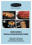
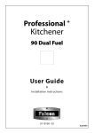
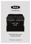
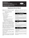
ArtNo.000-0005 Classic logo
Professional
ArtNo.000-0012 Professional + logo
+
ArtNo.000-0021 Toledo logo
90 Induction
Service Manual
ArtNo.000-0008 Falcon logo shaded
U110100 - 01sm
Australia
INSTALLATION
Check the appliance is electrically safe when you have finished.
Electrical Connection
This appliance must be installed by a qualified electrician
to comply with the relevant regulations (AS/NZS
60335.2.6:2002) and also the local electricity supply
company requirements.
Ensure that the mains characteristics (voltage, nominal,
power, etc.) match the ratings indicated on the data plate
affixed to the cooker.
ArtNo.132-0001 - 1 phase 240Vac 50Hz
The cooker is preset for a single-phase earthed electrical
connection. It is essential to install a multi-pole circuit breaker
that completely disconnects the appliance from the mains,
with a minimum contact break distance of 3 mm.
1-phase 240 VAC 50 Hz
Fig.7-6
Fig.7-7
Current Operated Earth Leakage Breakers
The combined use of your induction cooker and other
domestic appliances may cause nuisance tripping, so we
recommend that the cooker is protected on an individual
RCD (Residual Current Device) or RCBO (Residual Current
Breaker with Overload).
IF IN DOUBT, PLEASE CONSULT A SUITABLY QUALIFIED
ELECTRICIAN.
WARNING: THIS APPLIANCE MUST BE EARTHED
nn
Fig.7-8
The appliance must be connected to an efficient earthing
circuit. If the electricity network is not equipped with an
earth connection, then it must be installed separately in
compliance with local regulations.
Rear cover
Earthing is a safety measure required by law, and must be
performed with particular care by a qualified technician,
who must also check that the electricity supply
characteristics are correct.
Remove this area
The total electrical load of the appliance is approximately
17 kW. The cable size used should be suitable for this load and
comply with all local requirements (i.e. PVC Insulated cable
IEC 60227 – code 53 for ordinary cables).
Access to the mains terminal is gained by removing the
electrical terminal cover box on the back panel. Connect the
mains cable to the correct terminals for your electrical supply
type (Fig.7-6 and Fig.7-7). Check that the links are correctly
fitted and that the terminal screws are tight. Secure the mains
cable using the cable clamp.
Fig.7-9
Fixed Wiring
Conduit bracket
For connection to fixed wiring, i.e. flexible conduit, remove
the main rear cover.
Remove the electrical cable entry break out from the bottom
of the rear cover (Fig.7-8).
Centre upright
Fix the conduit bracket to the centre upright (Fig.7-9). Fit the
conduit up to the bracket and secure in place with the plastic
nut.
Connect the mains cable to the correct terminals for your
electrical supply type (Fig.7-10 and Fig.7-11). Check that the
links are correctly fitted and that the terminal screws are tight.
Secure the mains cable using the cable clamp.
26
INSTALLATION
Check the appliance is electrically safe when you have finished.
Refit the rear cover.
Repositioning the Cooker following
Connection
If you need to move the cooker once it has been connected,
make sure it is switched off at the supply switch before
gripping under the fascia panel and lifting the front of the
cooker slightly (Fig.7-5). Check behind the cooker to ensure
that the electricity cable is not caught. As you progress,
always ensure that the cable has sufficient slack to allow the
cooker to move.
ArtNo.132-0002 - 3 phase 240/415Vac 50Hz
3-phase 240/415 VAC 50 Hz
Make sure to release the stability chain as you ease the
cooker out. Do not forget to refit it when you replace the
cooker.
Fig.7-10
Fig.7-11
Mains terminal
When you replace the cooker, check behind it again once
more to ensure that the electricity cable is not caught or
trapped.
A
Hob Check
N
Fixing bracket for
conduit connection
Check each cooking zone in turn. Be sure to use pans of the
correct size and material.
Cable clamp
Grill Check
ArtNo.132-0005 - Fixed wiring connection 2 (AUS)
Turn on the grill control and check that the grill heats up.
Oven Check
Conduit
Set the clock as described earlier, and then turn on the ovens.
Check the oven fans start to turn and that the ovens heat up.
Fitting the Handles and Handrail (Classic
modelonly)
Remove the 4 mm Allen screws from the doors (Fig.7-12).
Fig.7-12
Fit the door handles and secure using the 4 mm screws
(Fig.7-13).
The handles should be above the fixings.
nn
ArtNo.215-0026 - Handle gaskets fixed
Remove the 4 mm Allen screws from the top corners of the
fascia (Fig.7-14). Fit the front handrail in position and secure
using the 4 mm screws.
Fig.7-13
ArtNo.210-0009 - Classic
removing the handles
Fig.7-14
Art No 215-0028 - Handrail fascia fixings
27
INSTALLATION
Check the appliance is electrically safe when you have finished.
Fitting the Plinth
Fig.7-15
Classic & Professional+ models
Loosen the three screws along the front bottom edge of the
cooker. Hook the central keyhole over the central screw. Twist
and fit each end keyhole over their respective screws. Tighten
the fixing screws (Fig.7-15).
Toledo model
Fit the inner plinth to the bottom front of the cooker using
the 5 screws provided (Fig.7-16.
ArtNo.000-0012 - Securing the plinth
Fit the outer plinth (2 screws, 1 each end) to the inner plinth.
The height of the outer plinth can be adjusted by sliding it up
or down via the slotted hole (Fig.7-17).
Fig.7-16
Fitting the Splashback (Classicmodelonly)
ArtNo.350-0010 - Fitting the plinth 1 (Kitchener)
The cooker can be installed with or without the supplied
splashback.
Position the splashback on the rear of the hotplate and secure
with the screws supplied (Fig.7-18).
Customer Care
Fig.7-17
Installer: Please complete your details in this Guide, inform
the user how to operate the cooker and hand oven the
instructions.
Thankyou.
ArtNo.350-0011 - Fitting the plinth 2 (Kitchener)
Outer plinth
Inner plinth
Outer plinth fixing screw
Fig.7-18
28
WARNING – SERVICING TO BE CARRIED OUT ONLY BY AN AUTHORISED PERSON
Disconnect from electricity before servicing. Check appliance is safe when you have finished.
8. Servicing
Disconnect the cooker from the electricity supply
nn
before servicing, particularly before removing any
Fig.8-1
of the following: control panel, side panels, ceramic
hob, or any of the electrical components or cover
boxes.
ArtNo.210-0008 - Classic
Removing the end caps
Before reconnection, check that the appliance is
nn
electrically safe.
1.
To Remove a Side Panel
Disconnectfromelectricitysupply.
Pull the cooker forward. Pull off the control panel end caps
at each end of the panel (Fig.8-1). Remove the fixing screws
under the end caps.
Fig.8-2
Remove the retaining screws for each panel (one at the front,
two at the rear, and one at each lower front corner of the side
panels).
ArtNo.210-0009 - Classic
removing the handles
Reassemble in reverse order.
2.
To Lift up the Ceramic Hob
Disconnectfromelectricitysupply.
Pull off the push fit control panel end caps at each end and
remove the end fixing screws under the end cap.
Remove the lower front retaining screws (one each side)
situated beneath the lower edge at the front corners of the
side panels.
Swing the side panels to gain access to the hob fixing screws
(1 each side) at the top front of the side uprights.
Remove these screws.
Lift up the ceramic hob at the front and prop into position
with a non-metallic prop.
CAUTION: The ceramic hob material is much more sensitive
to scratches on the underside than the top.
Take care not to touch or scratch the underside of the ceramic
as this will weaken the material and cause the top to shatter.
3.
To Remove the Control Panel
Classic only: Remove the handrail by unscrewing the 2 end
bracket fixing screws (Fig.8-2).
Pull off the control panel end caps at each end of the panel
(Fig.8-1). Remove the fixing screws under the end caps.
Pull off all the control knobs. Open the grill and right-hand
oven door and remove the control panel fixing screws
underneath the control panel. The screws directly below the
clock are for the clock fixing bracket, so do not remove them
at this stage.
Lift the control panel, pull forward and disconnect the wiring
from the rear.
Reassemble in reverse order. When replacing leads, refer to
the wiring diagram in this manual. Check the operation of the
timer.
29
WARNING – SERVICING TO BE CARRIED OUT ONLY BY AN AUTHORISED PERSON
Disconnect from electricity before servicing. Check appliance is safe when you have finished.
4.
Fig.8-3
To Replace a Hob Element
Disconnectfromelectricitysupply.
Lift up the ceramic hob (see 2). The Induction Heating
Elements (IHE) are now accessible. Note the wire connection
positions and element orientation for re-assembly. Disconnect
the 4 wires, and remove the element unit and the 3 springs.
Fit the new sealing ring around the fan vent (Fig.8-3) and refit
the 3 springs. Re-assemble in the reverse order.
Note: The IHE will require commissioning when the hob has
been refitted.
5.
To Replace the Light Switch
Disconnectfromelectricitysupply.
Remove the control panel (see 3).
Note: The old switch may be destroyed during removal.
Remove the old switch from its bezel by gripping the switch
body behind the control panel and twisting sharply. Remove
the switch bezel by folding back its locking wings and pushing
forward. Fit the new bezel to the control panel by first lining
up the raised key on its body with the cut-out in the control
panel and pushing it in from the front.
Assemble the new switch to the bezel by lining up the key
sections and pushing home. Fit the new button by pushing in
from the front.
Replace the Control Panel in reverse order and test for correct
operation.
6.
To Remove the Electronic Timer
Disconnectfromelectricitysupply.
Remove the control panel (see 3). Pull off the timer control
button(s).
Remove the timer/mounting bracket assembly from the
control panel by removing the fixing screws.
Remove the timer from its mounting bracket by depressing
the plastic lugs on the timer case, at the same time pulling the
unit forward.
Reassemble in reverse order. When replacing the leads, refer
to the wiring diagram in this manual. Check the operation of
the timer.
7.
To Replace the Grill Controller
Disconnectfromelectricitysupply.
Lift up the hob and remove the control panel (see 2 and 3).
Disconnect the wiring from the controller. Remove the two
screws holding the controller to the mounting panel. Fit the
new controller and reassemble in reverse order. Check for
correct operation.
8.
To Remove a Grill Element
Disconnectfromelectricitysupply.
Remove the grill pan from the grill compartment. Undo the
two screws and washers in the grill roof and remove the
enamelled front shield.
Undo the 2 screws and washers securing the grill element
front support. Remove the screws from the grill elements.
Lift the elements out carefully and, noting their position,
disconnect the leads from the element terminals.
30
WARNING – SERVICING TO BE CARRIED OUT ONLY BY AN AUTHORISED PERSON
Disconnect from electricity before servicing. Check appliance is safe when you have finished.
If it is not possible to disconnect the leads in this way, pull the
cooker forward to gain access to the rear. Undo the screws
securing the electric cover to the back sheet and remove the
cover. Disconnect the terminals from the rear.
Fig.8-4
Fig.8-5
Fit new elements and reassemble in the reverse order. Check
the operation of the grill.
9.
To Remove the Grill Door
2
1
Remove the left-hand side panel (see 1). Remove the control
panel (see 3). Remove the centre cover strip (5 screws, 2 top, 2
bottom, 1 in middle). Remove the two countersunk screws (1
each side) securing the grill hinge arms to the front of the grill
chamber.
ArtNo.320-0001 Door hinges
ArtNo.320-0001 Door hinges
Fig.8-6
Note: The arms are spring tensioned. Carefully remove the grill
door. Retain the gaskets.
Reassemble in reverse order, ensuring that the gasket is fitted
between the hinge arm and the front of the grill chamber.
Remove the two screws and washers securing the grill
element front support. Remove the screws from the grill
element.
ArtNo.320-0006 Oven door hinge adjustment 1
Lift the element out carefully, disconnecting the leads from
the element terminals (noting their position). If it is not
possible to disconnect the leads in this way, pull the cooker
forward to gain access to the rear, remove the screws securing
the electric cover to the back sheet, remove the cover and
disconnect the terminals from the rear.
Effect of hinge adjustment - exagerrated for clarity
Centreline of hinge pin
Fig.8-7
Fit the new element and reassemble in reverse order. Check
the operation of the grill.
10. To Replace an Oven Door
Open the oven door. Support the door and remove the two
screws securing the upper hinge and gasket to the cooker
front (Fig.8-4). Remove the door from the lower hinge by
lifting slightly and moving outwards (Fig.8-5).
ArtNo.320-0007 Oven door hinge adjustment 2
Oven door omitted for clarity
nn
The door is heavy, so take care.
Reassemble in reverse order.
Fig.8-8
11. To Adjust an Oven Door Angle
The bottom hinge of either oven door can be adjusted to alter
the angle of the door (Fig.8-6). Loosen the bottom hinge fixing
screws and use the notch and a flat bladed screwdriver to move
the position of the hinge to set the hinge position (Fig.8-7).
Retighten the hinge screws.
12. To Replace the Main Oven Door Outer Panel
ArtNo.320-0002a Proplus oven door side screws
Move the cooker forward to gain access to the sides.
Open the oven door slightly and remove the front panel fixing
screws from the door sides – two each side (Fig.8-8).
Fig.8-9
Carefully lift off the outer door panel.
Remove the door handle from the panel by unscrewing the
two retaining nuts. Fit the door handle to the new panel.
Fit the panel to the door. Reassemble in reverse order.
13. To Change the Main Oven Door Latch
Remove the outer door panel (see 12). Remove screws ‘B’ that
hold the latch assembly to the inner door panel (Fig.8-9). Fit
the new catch and reassemble in reverse order.
B
ArtNo.320-0003 Oven door latch
Verify the door operation.
31
Fig.8-10
ArtNo.320-0004 Oven door keep
WARNING – SERVICING TO BE CARRIED OUT ONLY BY AN AUTHORISED PERSON
Disconnect from electricity before servicing. Check appliance is safe when you have finished.
14. To Adjust the Main Oven Door Catch Keep
Fig.8-11
Open the oven door, and slacken off the locknut at the base of
the keep (Fig.8-10).
Screw in or out as required until the required fit is obtained.
Retighten the locking nut.
15. To Replace the Tall Oven Door Outer Panel
Remove the oven door (see 10). Lay the door face down on a
suitable surface and remove the two screws from the bottom
edge of the door and the two screws from the inside face of
the door.
Remove the outer door panel. Remove the handle by
unscrewing the two screws.
ArtNo.320-0005 Oven door rubber seal
Unscrew the two cross-headed screws holding the door
handle fixing bracket to the door panel. Fit the door handle
bracket and door handle to the new panel.
Fit the panel to the door and reassemble in the reverse order.
16. To Replace the Tall oven Magnetic Latch
Remove the control panel (see 3). Remove the plinth and the
central vertical cover (5 screws). Prise the retaining clip off the
magnet unit.
Fit the new unit and retaining clip, and reassemble in reverse
order. Check that the door operates correctly.
17. To Replace an Oven Door Seal
Open the oven door. The seal has small hooks that hold it in
place by locating into holes in the rear door face on the main
oven and oven front face on tall oven. At the corner, pull the
seal diagonally away from the door centre until the hook is
released (Fig.8-11). Proceed to the next hook and release it in
a similar way, and so on.
You can use force if the hooks are stiff, as the old seal will be
discarded.
Carefully lift away the inner back. Reassemble in reverse
order making sure that the four screws and washers are fully
tightened.
18. To Replace a Thermostat
Disconnectfromtheelectricitysupply.
Lift the ceramic hob and remove the control panel (see 2 & 3).
Open the oven door. Remove the oven furniture.
For the right-hand oven, remove the thermostat phial cover
(two screws). Unclip the thermostat phial from the clips in the
oven back.
For the left-hand oven, pull cooker forward to gain access
to the cover box at the rear of the cooker. Remove the four
screws securing the cover and lift clear.
Feed the thermostat capillary out of the oven. Disconnect
the wiring from the thermostat. Remove two screws holding
thermostat to mounting panel. Fit new thermostat and
reassemble in reverse order. Ensure that the phial is clipped to
the oven back with the phial centrally positioned between the
clips.
Check the operation of the thermostat.
32
WARNING – SERVICING TO BE CARRIED OUT ONLY BY AN AUTHORISED PERSON
Disconnect from electricity before servicing. Check appliance is safe when you have finished.
19. To Remove an Oven Element Thermal Cut-out
Fig.8-12
Disconnectfromelectricitysupply.
Pull the cooker forward to gain access to the cover box. Undo
the cover screws and lift clear. The cut-out is located on the
earth plate beside the oven element connections. Disconnect
the cut-out wiring. Undo the fixings that secure the cut-out to
the earth plate and remove. Fit the replacement control and
re-assemble in reverse order.
20. To Remove an Oven Inner Back
Disconnectfromelectricitysupply.
Open the door and remove the shelves. Remove the screws
and washers securing the inner back to the back of the oven
(Fig.8-12). Carefully lift away the inner back. Reassemble in
reverse order making sure that the screws and washers are
fully tightened.
ArtNo.320-0020 Oven back fixing screws
Fig.8-13
21. To Remove the Fan Oven Element
Disconnectfromelectricitysupply.
Element fixing screws
Remove the oven inner back (see 20). Remove the two screws
from the top of the element and the one from the bottom of
the element inside the oven (Fig.8-13).
Lift the element out carefully, disconnecting the terminals
connected to the element (noting their positions).
ArtNo.321-0005 Fan oven element
If it is not possible to disconnect the leads in this way, pull the
cooker forward to gain access to the rear.
Fig.8-14
Remove the screws securing the electric cover to the back
sheet, remove the cover and disconnect the terminals from
the rear.
Fig.8-15
22. To Replace an Oven Fan
Disconnectfromelectricitysupply.
ArtNo.324-0007 Unscrewing the bulb cover
Pull the cooker forward to gain access to the rear. Remove
the screws securing the electric cover to the back sheet and
remove the cover.
Disconnect the three terminals connected to the fan noting
their position. Remove the oven inner back (see 20). Hold the
fan blade and remove the centre nut (left-hand thread) two
brass washers, fan blade and circlip. Unscrew the fan retaining
nuts and washers (three off each) and lift the fan away from
the rear of the cooker. Fit the new fan and reassemble in
reverse order.
Check the operation of the oven.
23. To Change Oven Light Bulb
Disconnectfromelectricitysupply.
Make sure the oven is cool. Open the oven door and remove
the oven shelves. Remove the grill pan and support from the
grill chamber.
Unscrew the bulb cover by turning anticlockwise. It may be
very stiff (Fig.8-14).
Taking care to protect your fingers in case the bulb should
shatter, unscrew the old bulb.
Fit an Edison screw fitting 15 W 240 V lamp, FOR OVENS. It
must be a special bulb, heat resistant to 300 °C (Fig.8-15).
Screw in the new bulb, and then screw back the bulb cover.
Turn on the electricity supply and check that the bulb now
lights.
33
ArtNo.324-0005 Oven light bulb
Access To Remove Glass Induction Top
Remove grommet from LH &
RH Side panels
Fixing screw is located inside
Rear fixing screw (left & right)
Following removal of the 4 fixing screws
induction glass top can raised
Rangemaster Induction Models 90cm
Zone 3
Zone 2
Zone 5
YGP043491
YGP043491
YGP043491
Zone 1
Zone 4
YGP043492
YGP043492
YGP045186
Filter boards are located in a cover panel
below zones 3 & 4 (see below)
Rear of cooker
Cover panel secured by 3 screws at front &
2 in the rear (panel shown hinged down)
Filter
board A
Filter
board B
Filter
board C
Filter board A controls Zone 3 & 4
Filter board B controls Zone 5
Filter board C controls Zone 1 & 2
Filter
board A
YGP043544
Filter
board C
YGP045187
Filter
board B
YGP045187
Filter board A controls Zone 3 & 4
Filter board B controls Zone 5
Filter board C controls Zone 1 & 2
Filter
board A
YGP043544
Filter
board C
YGP045187
Filter
board B
YGP045187
General Error Codes
Error Code
Description
Error of Input unit
(Rotary Control)
Possible Error Cause
Permanent Operation of Rotary
Control or Broken Wire
between Rotary Control and UI
Board
Micro Defective
No failure
Error Correction
- Release Rotray Control
- Replace Rotary Control
- Replace Link Wire
Er20
H
Flash Error
Display of Residual Heat
Exchange UI Board
Cooling of Hob Required
E2
Overheating of Connection
Units
- Pot / Glass too high a
temeprature
- NTC Electronic too high
Cooling of the Power Board
Required
Error Code
Description
Possible Error Cause
Error Correction
No Display
Operation
Over - Voltage on switch
mmode power supply
C
C1
C2
E
No Failure
Basic Induction Codes
E3
E4
Blind Connection with 400 V
No Failure, User is in the
Service
S
i Menu
M
Mode
M d
Check Voltage Supply
Complete the Configuration
Process
P
This Error Code will be
relplaced after 8 S and the
Pot is creating an incorrect
- Unqualified Pot
unit can be used again.
working point on power board.
This may destroy some of the If the error code reappears the
- HW Failure
pot has to be removed and
components on the board
replaced.
1&2 Configure the IHE unit
using the service menu or the
IR diode.
1. IHE not Configured
3 Check the Power supply and
2. More than 1 IHE has the
also the connection between
same configuration
IHE not configured or NO
the Power Board and the
communication between IHE 3. IHE is not connected to
supply voltage or Filter Board is Connection Unit (CU).
and the UI Board
not enabling the Power to the 4 If none of the above clears
the fault,replace the IHE unit.
IHE
E5
Error on Filter Board
Filter Board Defective
Exchange Filter Board (CU)
E6
Error on Power Board
Power Board Defective
Exchange Power Board (IHE)
E9
Open Circuit/Short Circuit
value of coil sensor
Thermal Sensor defective or
not plugged in
Change Temperature
Senor/Coil Sensor
Induction Heating Element (IHE) Configuration Procedure
Fig.1
��������������
IMPORTANT:
The configuration process must be completed
within two minutes of turning on power to the
cooker.
1.
Turn the front left (zone 1) control
anticlockwise to ‘A’ and hold in position
(Fig.2).
Fig.2
�����������������
���������������
�����
8
C
8
8
��������������
8
Fig.4
Induction
3.
Rotate the front left (zone 1) control clockwise
to position ‘9’ (Fig.5); the display will show a
flashing E (Fig.6).
Fig.5
2.
Turn the rear left (zone 2) control clockwise
to Position ‘9’. Flick the control knob clockwise
beyond position 9 three times (Fig.3).
Fig.3
8
8
8
�����������
�����������
8
E
Induction
The display will now flash alternately between
C and 1 (Fig.4).
F200012-01
Fig.6
8
Induction
4.
Take a ferrous saucepan (it must be magnetic)
and place it on the Zone 1 hobplate (Fig.8
and Fig.9). The display will now alternate
between C and 2.
���������
���������
���
���������
2
Fig.9
������
������
������
������
������
8
Fig.10
Induction
Fig.8
���������������������
�����������������������
8
8
�����������������
���������������
�����
8
C
8
8
Fig.7
Place the saucepan onto the Zone 2 hobplate
until the display flashes repeatedly from C to
3. Repeat for Zones 3, 4 and 5 as the display
indicates.
This procedure registers the hob zones.
If the zones are registered correctly all five
displays will flash 8 (Fig.10). The hob is now
configured.
If the zone is registered incorrectly the five
display will flash 4.
8
8
Leave the control knob in position ‘9’ until the
display stops flashing then return the control
knob anticlockwise to ‘0’. The display will
once again flash alternately between C and 1
(Fig.7).
4
4
4 4
4
Induction
Note: If the hob has failed to register then switch
the appliance off for a few seconds to clear the
memory and repeat the above procedure.
9. Circuit Diagrams
ArtNo.095-0003 - Circuit diagram - 90 induction
Circuit Diagram: Hob
v
y
br
2.3kW
br
b
2.3kW
br
br
2.3kW
v
br
br
br
w
br
r
br
br
1.4kW
v
b
br
br
CU2
w
b
br
1.4kW
y
v
y
br
br
br
CU1
y
br
r
r
CU3
w
r
w
A
br
8
8
8
8
8
br
r
y
br
w
v
b
br
B
ArtNo.080-0051 - 90 Elan induction (hob) circuit diagram
br
br
C
D
br
br
E
br
F
G
Code Description
ColourCode
A
Touchlite panel
b
Blue
B
Distribution board
br
Brown
C
Left-hand front control
bk
Black
D
Left-hand rear control
or
Orange
E
Central control
r
Red
F
Right-hand rear control
v
Violet
G
Right-hand front control
w
White
CU1
Left-hand pair (slave) control unit
y
Yellow
CU2
Centre (slave) control unit
g/y
Green/yellow
CU3
Right-hand pair (master) control unit
gr
Grey
34
Circuit Diagram: Fan Oven
w
F
br
br
br
br
A1
bk
bk
J
r
w
v
r
bk
b
r
r
w
J
v
bk
o
g/y
P4
P3
2
P2
bk
br
1
P1
1
P1
P033458
gr
C2
2
P4 br
P3
P2
1
P1
1
P1
P033458
bk
P2
B2
1
v
g/y
y
gr
br
br
y
g/y
y
w
b
B1
J
C3
w
b
H
bk
G2
b
C4
b
br
b
o
H
b
b
w
B3
y
b b
w
C1
y
P1
P1
bk
P095199
y
B4
br
2
1
o
w
4
3
v
bk
y
v
y
br
b
o
A2
br
b
y
r
4
3
br
y
A3
v
G1
o
gr
Multi-pin
plug
y
w
br
r
bk
o
K
D
br
y
r
bk
b
br
gr
br
br
ArtNo.080-0064 90 induction (oven) circuit diagram
br
br
b
r
y
br
A
L
br
b
w b
w
w
b
v
N
Key
The connections shown in the circuit diagram are for single-phase. The ratings are for 240 V 50 Hz.
Code Description
Code Description
ColourCode
A1
Grill energy regulator
C3
Right-hand oven element
b
Blue
A2
Grill front switch
C4
Right-hand oven fan
br
Brown
A3
Grill elements
D
Clock
bk
Black
B1
Left-hand zoned oven thermostat
F
Cooling fan
or
Orange
B2
Left-hand oven thermostat front switch
G1
Oven light switch
r
Red
B3
Left-hand oven element
G2
Oven light
v
Violet
B4
Left-hand oven fan
H
Thermal cut-out
w
White
C1
Right-hand oven thermostat
J
Neon
y
Yellow
C2
Right-hand oven thermostat front switch
K
Connection block
35
g/y
Green/yellow
gr
Grey
10. Technical Data
INSTALLER: Please leave these instructions with the user.
DATA BADGE LOCATION: Cooker back, serial number repeater badge below oven door opening.
Connections
Electric
230-240 V 50 Hz
Dimensions
Overall height
minimum 905 mm
maximum 930 mm
Overall width
900 mm
Overall depth
602 mm (to fascia inc. splashback); 610 mm (over hotplate)
Refer to 'Positioning the Cooker'.
Ratings
2.3kW
2.3kW
2.3kW
ArtNo.313-0002 - 110 induction hob rating
1.4kW
1.4kW
Ovens
Energy efficiency class on a scale of A (more efficient) to G (less efficient)
Energy consumption based on standard load
Usable volume (litres)
Size
Time to cook standard load
Surface area of the grid
Grill
Main oven
Tall oven
Forced air convection
Forced air convection
2.5 kW
2.5 kW
A
A
0.85 kWh
0.99 kWh
67
66
Large
Large
38 minutes
49 minutes
1400 cm²
790 cm2
2.3 kW
Maximum total electrical load at 240 V: 17.1 kW (approximate total including oven lights, oven fan, etc.)
36