1
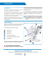
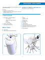
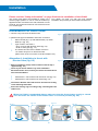
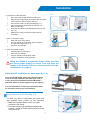
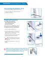
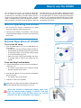
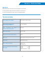
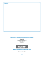
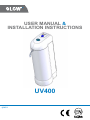
USER MANUAL &
INSTALLATION INSTRUCTIONS
UV400
4002
Introduction
Congratulations on your new water purifier
GLOW UV400!
The UV400 is designed for producing the water for
drinking and cooking of a normal household.
The water source must either be from the municipal
water system or well, aimed for personal consumption.
Make sure that the User Manual accompanies the UV400
if it is moved, resold or there is a change of owner so the
user will always have access to the complete instructions
and safety information.
For optimal function it is important that you read the
section entitled “Safety Information” on page 5 and that
you follow the installation instructions on pages 6-8 in
detail.
It is designed to give you plenty of clean water in years
to come, if correctly used and maintained.
We recommend that you refer to page 3
when reading the rest of this User Manual.
All bracketed numbers refer to figures 3.1
and 3.2.
Therefore, it is of the utmost importance to read the User
Manual thoroughly and must be kept in a safe place for
future reference.
Unpacking
Examine the water purifier for any signs of damage and
make sure that all accessories are included. See
fig. 2.
F
The following items should be included:
Water Purifier
B
Adapter 12 V
C
Wall Bracket
D
Diverter Valve with hose
E
External Thread Insert (and washer)
F
User Manual
fig. 2
Should you discover any damage, faults, or anything
missing, you should notify your dealer immediately.
E
Keep packaging material and
plastic bags out of children’s reach.
Guide to use the Manual
The following symbols will be found in the text to guide you throughout the instructions:
Safety information
Hints and information
Description of the UV400
The UV400 purifies water through filtration and disinfection with UV light.
It requires:
A water source with pressure
Voltage, 100 V to 240 V, 50 Hz to 60 Hz. The socket
fitting the Adapter 12 V (9).
All features are operated with a one-touch button - The
Blue Button (1) - guided by the Green Lamp (2) and
Red Lamp (3) on the control panel.
•
•
Control Panel
1
1 Push Button (The Blue Button)
2 • UV Lamp On
• Water Flow Start and Stop
• Flush
• Auto Filling
2 Green Lamp (Ready)
3 Red Lamp (UV Monitor)
Other Parts
5
6
6 Body
7 Bottom Cover
8 Filter Lock
9 Adapter 12 V
10
DC Plug
11
Wall Bracket
12
Diverter Valve with hose
13 External Thread insert (and washer)
14 Speedfit Connector with 3/4” nut
15 User Manual
4 Top Cover
5 Water Pipe (Purifier Water Outlet)
4
fig. 3.2
fig. 3.1
Contents
2
Introduction
3
Description of the UV400
5
Safety Information
6
Installation (Inlet Hose to faucet with Diverter Valve)
7
Installation (Inlet Hose directly to water pipe)
Installation (Connecting the Adapter 12 V/Flushing)
8
9-10
How to use the UV400
11
Maintenance (Replacing the Carbon Block Filter)
12
Maintenance (Replacing the UV Lamp)
13
Maintenance (Replacing the Quartz Sleeve)
14
Maintenance (Cleaning the Quartz Sleeve)
15
Maintenance (Cleaning the Coarse Filter)
16
Regular Care
17
Trouble Shooting: Electrical
18
Trouble Shooting: Water / Consumables
19
Service / Technical Data
20
Company Information
Safety Information
General
The UV400 is an extremely safe water purifier. However,
it is important that every user of this product is familiar
with its use and safety features.
To prevent mishaps and problems, read the “Safety
Information” in this chapter thoroughly and carefully
follow the “Installation” instructions on pages 6 to 8.
• The water from the UV400 should only be consumed
•
•
when the UV400 has been properly maintained and
the UV monitor’s Green Lamp (2) is lit. Turn to pages
6 to 15 for Installation and Maintenance.
Do not change or attempt to modify the UV400. This
could result in personal injury and/or damage to
property. These eventualities are not covered by any
warranty.
Once a month the connection should be checked for
leakage.
• If the UV400 is malfunctioning, disconnect the adapter
from the wall socket.
• The water supply to the UV400 must have a normal
temperature (between 2 0C and 44 0C) .
If the water supply to the UV400 could be unfit for
human consumption, the purified water from the UV400
should be tested and approved for consumption. The
tests should be carried out once a year.
Only use the original 12 V adapter. Use the Adapter
12 V (9) in normal room temperature and avoid direct
sunlight.
The UV400 should not be installed in any location,
where the temperature can fall below +2°C (35 °F).
The UV 400 is compact and heavy for its size especially
when filled with water. Thus, it should be handled with
care to avoid dropping it that would cause damage.
•
•
•
Installations and service
of the UV400. Old hoses should be replaced by the
• Only install the UV400 in an upright vertical position. new included hose (12).
• Only use those types of hose and connectors ap- • Never install an ice-machine or any appliance to the
proved for full line water pressure, when connecting
•
•
the UV400 to its water source.
Verify that the installation is approved by your
insurance company.
Included hose (12) should be used for the installation
•
UV400 Water Pipe (5). Use only original spare parts
recommended by GLOW.
Always connect the Adapter 12 V (9) to a socket in a
dry location.
Using the UV400
or mental capabilities, or lack of experience and
• The UV400 is designed to produce water for drinking knowldege, unless they have been given supervision
and cooking for a normal household.
or instruction concerning use of the UV400 by a
• The UV400 must never be used without the Carbon person responsible for their safety. Children should
Block Filter, except during the descaling procedure.
be supervised to ensure that they do not play with the
• Never block the Water Pipe (5) of the UV400.
UV400.
• Never connect a hose to the Water Pipe since it can • When the UV400 is unattended always make sure
accidentally get folded and cause damage to the
•
that the faucet (water supply) is closed. Turn and
leave the handle of the Diverter Valve in a vertical
position (for Alternative A installation on page 6).
UV400. This kind of damage is not covered by any
warranty.
The UV400 is not intended for use by persons
(including children) with reduced physical, sensory
Installation
Please read the “Safety Information” on page 5 before the installation of the UV400.
The UV400 must always be installed for usage in the
vertical upright position. It can be used as a table top
appliance and/or mounted on the wall, whatever is most
practical. The UV400 can either be connected to a faucet
or to a water pipe.
Your dealer can help you with the most suitable
installation and provide you with needed accessories.
Installation of Inlet Hose
1.Choose a dry area near the kitchen sink.
fig. 6.1
•
•
•
2.Decide what type of installation and water connection.
Wall mounted (fig. 6.1) with Wall Bracket (11) and/or
table top? (fig. 6.2)
Type of water connection?
- Alt A. to faucet with Diverter Valve (fig. 6.2)
- Alt B. to water pipe (fig. 7.4).
The UV400 should not be installed more than
1.8 meters away from an electrical outlet
(within reach of the connection of the DC Adapter 12V).
Alternative A: Installation to faucet with
Diverter Valve (fig. 6.2)
fig. 6.2
• Before installation, always remove strainer from the tap if
applicable (fig. 6.3)
Check
if your faucet matches any of the installation
•
alternatives below. If not, contact your dealer for further advice
and recommendations.
•
•
Alternative A1: Faucet with outer thread 22 mm (fig. 6.4)
Alternative A2: Faucet with inner thread (fig. 6.5)
• Connect the Diverter Valve with hose to the faucet according
to the matching Alternative.
Screw
the locking ring according to fig. 6.6 and tighten the
•
rubber seal.
When the UV400 is unattended always make sure that the faucet (water supply) is closed.
Turn and leave the handle of the Diverter Valve in a vertical position (fig. 6.6).
fig. 6.3
fig. 6.4
fig. 6.5
fig. 6.6
Installation
3. Connection of the Inlet Hose.
Place the water purifier where it will be used.
Determine the right length of the Inlet Hose and place it there where it does not get in the way.
Cut the Inlet Hose to its proper lenght (fig. 7.1).
See to it that there are no folds in order for the water to flow freely.
Insert the Inlet Hose to the Speedfit Connector (15)
(fig. 7.2).
Make sure it is fully inserted and locked when
it is pulled.
•
•
•
•
•
•
fig. 7.1
fig. 7.2
fig. 7.3
4. Turn on the water supply
Open the valve of the faucet.
Turn the handle of the Diverter Valve clockwise
to horizontal position (fig. 7.3).
Check for any leakage.
•
•
•
5. Turn off the water supply.
Close the Valve of the faucet.
Check for any leakage.
Turn the handle of the Diverter Valve counter clockwise to vertical position.
•
•
•
When the UV400 is unattended always make sure that
the faucet (water supply) is closed. Turn and leave the
handle of the Diverter Valve in a vertical position (for Alt.
A installation on page 6).
Alternative B: Installation to water pipe (fig. 7.4)
fig. 7.4
Since the GLOW UV400 works with a Solenoid Valve,
it can be directly installed to the water pipe. This is
a more permanent installation and GLOW UV400’s
automatic features can be enjoyed to its full capacity.
It is recommended to contact your authorized dealer
for assistance for this type of installation.
Disconnection of the hose (fig. 7.5)
fig. 7.5
In case you need to disconnect the hose from
the installed water purifier, do the following:
Make sure that the water is OFF (no water
pressure in the hose).
Push the locking ring (highlighted) against the
housing (arrow A), at the same time pull out the
hose (arrow B).
A
•
•
B
Installation Connecting Adapter 12 V / Flushing
Connecting the Adapter 12 V
1.Connect the DC Plug (10) to the UV400 (fig. 8.1).
2.Connect the Adapter 12 V (9) to the electrical socket in a dry location.
fig. 8.1
Flushing Procedure
The UV400 should be flushed:
• after installation of the UV400
• after replacement of filter
• Descaling Procedure
fig. 8.3
Never consume the flushed water. During
the flushing the UV Lamp is not lighted which
means that the water does not get sterilized.
1. Disconnect the DC Plug (fig. 8.2).
fig. 8.2
2. Push The Blue Button (1) and keep it
pressed (fig.8.3) at the same time as the
DC Plug (fig. 8.4) is reconnected.
fig. 8.5
3. After a short time the Solenoid Valve will
open and water will enter the UV400.
4.
Keep The Blue Button pressed down
during the entire flushing procedure
(fig. 8.5).
5.Release The Blue Button to stop the
flushing.
fig. 8.4
When the UV400 is unattended always make sure
that the faucet (water supply) is closed. Turn and
leave the handle of the Diverter Valve in a vertical
position (for Alt. A installation on page 6).
How to use the UV400
The UV400 is easy to use. Just press The Blue Button (1). Thanks to modern and advanced electronics,
all features are controlled by the Blue Button with the
guidance of the Green (2) and Red (3) Lamp. The first
“push” of the Blue Button (1) will activate the UV lamp inside the UV400. The Green Lamp will blink for about 20
seconds before you can draw water. During this period
the UV lamp is preheated for optimum disinfection. After
this the Blue Button is used for opening and closing the
water flow. The UV400 will automatically shut off when
it is not in use (the solenoid valve is not opened) for approximately 30 seconds.
Before operating the UV400
fig.9.1
1.Be sure that the UV400 is connected to its water
source and that the water pressure is on.
2.Verify that the UV400 is connected to the DC Plug
(10) and that the Adapter 12 V (9) is connected to the
wall socket.
Normal Operation of UV400
Turn-on the UV Lamp
fig.9.2
1.Push The Blue Button (1) once to TURN-ON the UV
lamp (fig.9.1).
The Green Lamp (2) should be blinking slowly for
approximately 20 seconds the first time (5 seconds
for following usage, as long as the voltage supply
is not disconnected). (fig. 9.2)
When the Green Lamp stops blinking and stays
lit, purified water is ready to be drawn from the
UV400.
•
•
Draw and Stop Purified Water
fig.9.3
2. Push the Blue Button one more time for DRAWING water (fig. 9.3).
The Green Lamp should now be blinking rapidly
that the solenoid valve is open.
•
3.Push the Blue Button, one more time for STOPPING
the flow of water.
The Green Lamp should stay lit.
•
4. Sequence 2 and 3 are repeated.
Reminder: The Green Lamp and the UV light will shut
off automatically after 30 seconds if not in use.
When the UV400 is unattended always make sure
that the faucet (water supply) is closed. Turn and
leave the handle of the Diverter Valve in a vertical
position (for Alt. A installation on page 6).
How to use the UV 400
With the Auto Filling feature you can draw the desired
amount of water in multiples of 0.5 l (amount of water
during 30 seconds.) This is very practical since you can
do other things while filling up your pitcher or container.
Before using the Auto Filling function the UV400
should be in ready mode (UV Lamp should be lit).
Auto Filling
1.Push the Blue Button (1) and keep it down while observing the following:
That the Green Lamp (2) blinks slowly.
And is constantly lit (fig. 10.1).
fig.10.1
•
•
2.Release The Blue Button when the desired number of
flashes is reached. Each flash corresponds to
0.5 l (> 2 bar and new filters).
Examples:
3 flashes correspond to 3 x 0.5 l = 1.5 l
5 flashes correspond to 5 x 0.5 l = 2.5 l
fig.10.2
Make sure that your container is big enough for
the desired amount of water.
Never leave the room when drawing water from
the UV400. Always make sure that the water
really stops before the container overflows.
fig.10.3
When the UV400 is unattended always
make sure that the faucet (water supply)
is closed. Turn and leave the handle of the
Diverter Valve in a vertical position (for Alt.
A installation on page 6).
10
Maintenance
Replacing the Carbon Block Filter
fig.11.1
The Carbon Block Filter has to be replaced when:
The water flow has been reduced to about half of its
full capacity.
It has been in use for 6 months.
•
•
1.Disconnect the DC Plug (10) from the water purifier.
2.Place the UV400 near a water outlet (normally the
kitchen sink) and be prepared for water to come out.
fig.11.2
3.Open the Bottom Cover (7) by turning it counter
clockwise (fig. 11.1) and pull it out together with the
attached Carbon Block Filter (fig. 11.2).
4.Be prepared for excess/left-over water to come out.
fig.11.3
5.Clean the inside of the Filter Chamber with a small
brush and rinse with clean water.
6.Press the lock located at the center of the Bottom
Cover towards the direction as shown in fig. 11.3.
7.Detach the old Carbon Block Filter and insert the
NEW Carbon Block Filter into the Bottom Cover.
fig.11.4
Make sure that the rubber seal is properly fitted
as shown in fig. 11.4.
Lubricate the rubber seal with any vegetable oil for
easier fitting when tightening the Bottom Cover (fig.
11.6).
8.Push the Filter Lock (8) back to the center of the
Bottom Cover (fig. 11.5).
fig.11.5
9.Insert the Bottom Cover with the NEW attached
Carbon Block Filter and tighten the Bottom Cover
clockwise (fig. 11.6).
9.Flush the UV400 for 5 minutes before using it again.
See “Flushing Procedure” on page 8.
fig.11.6
11
Maintenance
Replacing the UV Lamp
It is rare that the UV Lamp has to be replaced, since the
UV400 has a shut off timer. However, certain conditions
might cause damage or break the UV Lamp.
fig.12.1
Hold the end of the UV Lamp (metal cap) when
connecting and disconnecting the terminal(s).
Never pull the wire(s) for detaching the terminals of the
UV Lamp.
fig.12.2
Disconnecting UV Lamp
1.Disconnect the DC supply to the UV400.
2.Open the Top Cover with a coin by twisting it
(fig. 12.1).
3.Disconnect the terminal (fig. 12.2) by pulling it up at
the same time holding the end tip (metal cap) of the
UV Lamp.
4.Pull up the UV Lamp carefully (fig. 12.3).
5. Disconnect the bottom-end of the terminal (fig. 12.4).
fig.12.3
Installing UV Lamp
6.First connect the bottom-end terminal (with white
wires) (fig. 12.5) by fitting the terminal to the two pins
of the UV Lamp.
7.Insert the UV Lamp with the connected bottom-end
terminal into the Quartz Sleeve (fig. 12.6).
8. See to it that the UV Lamp is fully inserted.
9. Reconnect the top terminal (with blue wires) to the
two pins of the UV Lamp (fig. 12.7).
10. Refit the Top Cover and push it down until it snaps
in place (fig 12.8). Make sure that no cables are
squeezed.
11. Re-connect the DC supply.
fig.12.4
Only use GLOW’s original UV Lamp to ensure proper
disinfection and function.
A different type of UV Lamp can harm the electronics,
which would not be covered by the warranty.
Do not touch the glass of the UV Lamp since fingerprints can reduce UV transmittance.
fig.12.5
fig.12.7
fig.12.6
12
fig.12.8
Maintenance
Replacing the Quartz Sleeve
Before replacing the Quartz Sleeve, disconnect and
remove the UV lamp. Refer to fig. 12.3 in “Replacing the
UV Lamp” on page 12.
fig.13.1
1.Unscrew the Quartz Sleeve Holder (fig. 13.1).
2.Pull out the Old Quartz Sleeve together with the
O-ring (fig. 13.2).
3.Insert the new Quartz Sleeve with the O-ring(fig.
13.3).
4.Fit and screw the Quartz Sleeve Holder and tighten
the Silicon O-ring hard (fig. 13.3).
If the Quartz Glass is broken, replace it immediately.
Make sure that there are no remaining shards of
glass from the Quartz Sleeve in the UV chamber.
Broken Quartz Sleeve should be kept away from
children’s reach and disposed of appropriately.
fig.13.2
fig.13.3
13
Maintenance
Cleaning (Descaling) the Quartz Sleeve
1.Disconnect the DC plug (10).
fig.14.1
2.Remove the UV Lamp (see page 12). Follow
instructions 1 to 5.
3.Unscrew the Quartz Sleeve Holder (fig. 14.1).
4. Pull out the Quartz Sleeve together with the Silicon
O-ring (fig. 14.2). Be careful not to drop or damage
the Quartz Sleeve.
fig.14.2
5.Prepare a solution of water and vinegar for
cleaning and descaling of the Quartz Sleeve.
6.Wet a clean cotton cloth with the water and vinegar
solution.
7.Gently rub the outside surface of the Quartz
Sleeve with the wet cloth cleaning it thoroughly
(fig. 14.3).
fig.14.3
Make sure that the inside of the Quartz Sleeve
does not get wet. This could later short-cut the
UV Lamp.
Avoid touching the Quartz Sleeve directly with the
fingers below the Silicon O-ring.
8.Insert the newly-cleansed Quartz Sleeve Holder
and tighten the Quartz Sleeve holder (fig. 14.4).
fig.14.4
9.Insert and re-connect the UV Lamp, (see
instructions 6 to 11 on page 12).
14
Maintenance
Cleaning the Coarse Filter
If the water supply contains a lot of sediments the Coarse
Filter can get saturated.
fig.15.1
Before Cleaning the Coarse filter
1. Disconnet the DC Plug (10) of the UV400.
2.Close the tap/valve of the water supply to the
UV400.
Cleaning the Coarse Filter
fig.15.2
3. Put the UV400 carefully on the side.
4. Unscrew the hose connector from the Solenoid Valve
(fig 15.1).
5. Grip the Coarse Filter with a small plunger and pull it
out of the Solenoid Valve (fig. 15.2).
6. Clean the Coarse filter with a brush and water (fig.
15.3) and push it back into the solenoid valve with a
plier (fig. 15.4).
7. Refit the water inlet hose.
8. Open the tap to the water supply and verify that the
water inlet connection does
not leak.
9. Connect the DC Plug to the UV400.
fig.15.3
fig.15.4
15
Regular Care
Things to Remember
Frequency of descaling
Listed are the things you need to remember for the
regular care and maintenance of your UV400.
• Check the function of the Green Lamp (2) every time
the UV400 is in use.
•
Calcium Ca2+
and
Magnesium
Mg2+
Water hardness
ºd
(German water
hardness
standard)
Period
between every
descaling
procedure
- 50
-7
6 months
50 - 100
7 - 14
3 months
100 - 140
14 - 20
1 month
mg/l
Never leave the room with the Green Lamp flashing,
which means the UV400 will NOT automatically shut
off since the solenoid valve is open.
• Check weekly that all connections to the UV400 are
properly sealed.
• Always unplug the UV400 if it is not used for a long
time.
• Always carry out the descaling procedure regularly.
• If the water supply has been classified as unfit for
drinking, the water from the UV400 should be tested
frequently.
• Avoid installing the UV400 in a hot or cold area or
where it is exposed to direct sunlight.
• Never connect an equipment or a hose to the water
outlet of the UV400.
The Carbon Block Filter needs to be replaced when
the water flow has been reduced to half compared
to when the filter was new, or every 6 months.
For an immediate shut down of the UV400, simply
disconnect or unplug the adapter.
Never pour water over the water purifier or dip it in
water.
Never let the Adapter 12V get wet. Never clean the
adapter with a wet or damp cloth.
16
Trouble Shooting: Electrical
The UV400 has several built-in safety features indicated
by the Red and Green Lamp on the Control Panel.
Symptoms/Warnings
Check
UV light and disinfection assurance
Red Lamp (UV Monitor) (3) shines steadily
• If the UV Lamp is damaged, replace the UV Lamp *
• If the UV Lamp is not properly connected
Assure that the UV Lamp terminals are
properly fitted to the pins of the UV Lamp
• If any wires have gotten detached
from the UV Lamp terminal(s)
Red Lamp (UV Monitor) and Green
Lamp (Ready) are flashing together.
Over Current Protection
The room and water are too cold, below 4 degrees
Avoid cold water or areas
•
• UV Lamp terminal electrically shortcut by water
Check if the end of the UV is wet
Check if the Quartz Glass Sleeve has water inside
The Lamp does not light up, nothing happens
UV Monitor Red Lamp and Ready
Green Lamp are flashing
• You press the Blue Button too quickly
• The unit is not properly connected to the electrical source
• Incorrect Adapter 12 V
• Incorrect voltage
You might use wrong 12 V adaptor
* Only use original spare parts and consumables.
17
Trouble Shooting: Water
If the water which comes out of the unit is
of poor quality or if the unit is leaking
Symptoms/Warnings
Check
If no, or only a little amount of water comes
out of the UV400, despite the Green Lamp
flashing (Solenoid Valve being open).
• Is the water on and the pressure high enough?
• Is the Carbon Block Filter old and/or saturated?
If so replace filter.
• Is the Coarse Filter clogged? Clean it.
• Is the Bottom Cover tightened?
• Is the Sleeve Holder tightened?
• Is the inlet hose to the purifier connected properly.
• Has the unit not been used for a long period? Run the
UV400 for at least 5 minutes. Dispose the water.
• Let the UV400 run for about 10 minutes before initial use.
• Is the Carbon Block Filter old? The activated
Water leaks from the UV400
Bad smelling water
carbon effect might have been depleted.
The first time the UV400 is used or after a new
• filter
is installed, the UV400 may drip constantly
The UV400 drips constantly
•
•
•
before all air has disappeared. This normally
disappears after a short period of time.
No Carbon Block Filter is used. Install a new one.
Old Carbon Block Filter is used. Replace it.
Too low water pressure could keep the
Solenoid Valve from closing properly.
Consumables / Spare parts
If the UV400 does not work properly, we recommend
that you start to use the Trouble Shooting (see page 17
and page 18), before calling for service.
We also recommend that you always keep an extra
Carbon Block Filter available if it needs to be replaced.
Contact your authorised dealer for consumables and
spare parts.
The UV Lamp and Quartz Sleeve rarely need to be
replaced. However, certain conditions might damage
them.
The filter is the part which normally has to be relplaced
reguraly for proper function.
Spare Parts:
UV Lamp
Carbon Block Filter
18
Quartz Sleeve
Service / Technical Data
Service
Before calling service, take down notes of the problem of your UV400.
For easy and faster support note down the product no. and serial no.
For service and spare parts, please contact your authorized dealer.
Technical Data
Power Supply to 12 V Adapter
100 V to 240 V, 50 Hz to 60 Hz
Power Supply to Water Purifier
(Only use original adapter)
12 V DC, stabilized
Power Consumption with Adapter
included: when pouring water:
12
V Max 20 W
Water line pressure:
0.5 bar – 8 bar
Weight (water purifier without water):
3.0 Kg
Water Flow :
approximately 2.7 litres per minute > 2 bar
Dimensions:
h36 x w12 x d19 cm
Water supply temperature:
Minimum 2 0C
Maximum 44 0C
Recommended water source for normal
filter usage
Turbidity
< 1 FNU
Chlorine
< 4 mg/l
Organic substances < 1 mg/l
19
Dealer:
The UV400 is developed and marketed by Glow AB.
Glow AB
Kopparbergsvägen 6
SE- 722 13
Sweden
www.glowinternational.net
Made in the E.U.
20