1
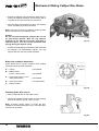
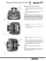
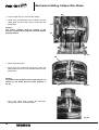
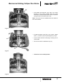
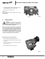
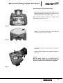
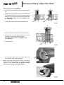
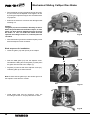
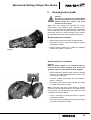
Assembly and Maintenance Instructions Mechanical Sliding Calliper Disc Brake Type PAN 19-1 1st Edition 8150100633 815 010 063 3 This publication is not subject to any update service. New versions are available in INFORM at www.wabco-auto.com Copyright WABCO 2006 Vehicle Control Systems An American Standard Company 8150100633 The right of amendment is reserved Version 001/10.03(en) 815 010 063 3 Table of contents Page 1. 2. Description of the mechanical sliding calliper disc brake 4 1.1 4 Introduction Service instructions 5 2.1 Safety tips during repair 5 2.2 Checking brake function 5 2.2.1 Checking adjuster function 6 2.3 Checking brake pads 7 2.4 Checking brake disc 8 3. Renewing brake pads 4. Renewing brake 16 5. Renewing gaiters 18 5.1 Renewing guide pin gaiters and bushes 18 5.2 Renewing adjuster screw gaiter 23 6. 8 Renewing brake cylinder 25 Table 1: Spanner widths [AF] and tightening torques [Nm] 26 Note: The Service Instruction focuses on trained specialists. Operations on the brake can only be carried out if the appropriate paragraphs have been read through and understood. The safety instructions according to paragrahph 2.1 are to be considered and to be followed. These Service Instructions are copyright. All rights reserved. This publication is not subject to any update service. You will find the latest versions in INFORM under www.wabco-auto.com when quoting the publications number 815 010 063 3 No part of this publication maybe reproduced, stored in a retrieval system, or transmitted in any form or by any means, electronic, photocopying, recording or otherwise without permission in writing from WABCO. 1 3 PAN 19-1 Mechanical Sliding Calliper Disc Brake 1. Description of the mechanical sliding calliper disc brake 1.1 Introduction The brake PAN 19-1 is a new developed onepiston-brake, which is intended for use in commercial vehicles and trailers on front and rear axles for 19,5" or 22,5" wheel rims as service, auxiliary and parking brake. It is actuated mechanically via a diaphragm brake cylinder or a spring brake cylinder. This cylinder is mounted to the end cover of the brake calliper. A very compact unit is achieved by the direct mounting of the brake cylinder onto the calliper. This enables optimal utilisation of the installation situations. The complete disc brake including brake cylinder consists of two assemblies: • Brake calliper (1) • Brake Carrier (2) The radially open design of the brake calliper allows a simple and quick change of the brake pads. Brake pads with a large wear volume are used in order to prolong the pad replacement intervals with this brake. The internal moving components are lubricated for life and all sealing components are maintenance free unless damaged. The disc brake is equipped with an electrical wear indicator (40). 1 2 Fig. 1 4 Mechanical Sliding Calliper Disc Brake 2. Service Instructions A second technican must assist during removal and installation of the brake. Heavy load - Danger of bodily injury! This instruction with the following pictures contains the required steps and work sequences to replace the available repair kits. The spanner size and the tightening torques in the sequneces are listed in table 1 (see page 26). For lubrication use only the tube of grease supplied with the brake repair kit. 2.1 PAN 19-1 During repairs outside of the vehicle, the brake must be secured in a fixture, such as a heavy vise as high torque is required during removal and installation of the bolts. Danger of bodily injury! Safety tips to be considered during repair The flawless technical condition of the disc brake is most important to ensure good driving and safe braking characteristics. The brake calliper with clamping unit shall not be opened. Therefore the bolts holding the cover shall not be loosened. Only original and genuine WABCO service parts and approved brake pads are to be used. Observe brake pad and disc wear limits! Worn-out pads and discs reduce the brake effectiveness and cause brake failure! Danger of accidents! Burned, glazed or oil contaminated brake pads must be replaced immediately. Always replace brake pads on a per axle basis! During repairs on the brake the vehicle must be parked on a level surface and be blocked to prevent rollaway. Only approved and suitable fixtures are to be used for the lifting and blocking of the vehicle. While working on the brake it must be ensured that the brake cannot be actuated inadvertently. Do not actuate the brake while the brake pads are removed. Danger of bodily injury! Do not clean the brake with pressurised air or other high cleaning pressure apparatus. Danger of bodily injury! Keep hands and fingers out of the inside of the calliper to avoid injury! During repairs use only recommended tools. Do not use a power-driven socket or tools! Tighten nuts and bolts only to specified torque limits. With newly installed brake pads on the first 50 km no emergency stops should be made. Also avoid long braking cycles and forced brakings. When wear of the cast brake parts such as cracks or heavy abrasion is noticied replace the entire brake assembly according to the instructions. Upon completion of repairs the vehicle's braking system must be tested on a roller dynamometer. If no roller dynamometer is available a driving test with brake applications must be perfomed. 2.2 Checking Brake Function Caution: Do not use a power-driven socket! While working at the brake or moving of the brake calliper handle the callipercalliper only from outside to avoid injury! 5 PAN 19-1 Mechanical Sliding Calliper Disc Brake 2.2.1 Checking adjuster function General note: The turning directions and the torques for the hexagon on the adjuster nut are given in table 1, position I. Work sequences: • 12 Remove plug (12) for the adjuster from the calliper (22) carefully. Caution: On disassembly the proper tool position is against the plug 12 (left side in fig. 2)! Do not place the tool between calliper and outer side of the sealing ring, otherwise the inner sealing might be damaged ( right side in fig. 2) • Using a AF 8 ring spanner (table 1, position I) turn the adjuster (22) hexagon approx. 1/2 turn clockwise. Caution: Do not overload the adjuster hexagon! Do not use an open-ended spanner. With the ring spanner mounted on the adjuster nut ensure that there is sufficient space, soit will not be prevented from turning during the adjuster check. • Fig. 2 Actuate the brake about approx. 5 times (apprx. 1 bar) The adjuster is functioning when the ring spanner (arrow) turns anti-clockwise with every brake actuation. Note: With increasing adjustment increments the angular movement of the ring spanner becomes smaller. The adjuster is in order when the ring spanner rotates as described above. • Remove ring spanner. • Refit plug (12) and ensure that the plug is placed properly. 12 22 Fig. 3 Failures that might occur: If the adjuster (22) respectively ring spanner (arrow) a) does not turn b) turns only with the first actuation c) turns forward and backward with every actuation, the adjuster is not ok. Change the brake according to section 4! 12 22 Fig. 4 6 Mechanical Sliding Calliper Disc Brake 2.3 PAN 19-1 Checking brake pads Note: The brake pad thickness needs to be checked regularly depending on operating conditions during maintenance intervals and under applicable local laws and regulations. Burned, glazed or oil contaminated brake pads must be replaced immediately. Always replace brake pads on a per axle basis! Work sequences: Friction material Caution: To avoid damage to the brake disc, the brake pads should be replaced at the latest when the thinnest section of the friction material is 2 mm. The thickness of the residual friction material should not be less than 2 mm. A = residual friction material thickness 2 mm. B = total friction material thickness 21 mm Fig. 5 At residual friction material thickness A < 2 mm renew brake pads according to section 3. Measuring of wear The average brake pad wear can be measured, depending on the access, at the close fit (longer guide pin at the brake disc entry) or at the clearence fit (shorter guide pin at the brake disc exit). Y X Therefore measure the thickness (X) of the flange of the axle and the distance (Y) between the flange and the edge of the brake calliper of the particular close fit (arrows). The maximum wear is reached or exceeded wtih the following values. Shorter guide pin: maximum wear X+Y > 95 mm. Change lining. Fig. 6 Longer guide pin: maximum wear X+Y > 122 mm. Change lining. 7 PAN 19-1 2.4 Mechanical Sliding Calliper Disc Brake Checking brake disc Work sequences: • Remove brake pads according to section 3 and measure the thickness of the disc in the contact area of the brake pads. C = total disc thickness - new 45 mm D = wear allowance limit 37 mm, the brake disc must be renewed. The renewal is recommended on a per axle basis. E = total pad thickness new 30 mm F = pad backplate thickness 9 mm G = minimum residual friction material thickness 2 mm H = absolute minimum pad thickness 11 mm, the brake pads must be renewed. Caution: Observe brake pad and disc wear limits! Worn-out pads and discs reduce the brake effectiveness and cause brake failure! Danger of accidents! 3. Fig. 7 Renewing brake pads Caution: Do not use a power-driven socket! While working at the brake or moving of the brake calliper handle the calliper only from outside to avoid injury! 38 40 Work sequences for removal of pads: • Disconnect cable of the wear indicator (40) at the plug (arrow). • Remove hexagon bolt (39) with spanner AF 17 (table 1, position II) from pad hold-down hoop (38). 39 Fig. 8 8 Mechanical Sliding Calliper Disc Brake PAN 19-1 1 38 • Pad hold-down hoop (38) has to be withdrawn from the calliper (1). • Remove three hold-down springs (37) from the brake pads (35 and 36) and the spreader plate (19). • Remove cable guide (40) and contacts from the brake pads. • Both cable clips (41) have to be removed from the brake calliper. • Remove plug (12) for the adjuster (22) of the calliper (1) carefully. Fig. 9 41 19, 37 37 36 40 35, 37 Fig. 10 Caution: While disassemblying plug (12) please note the instructions for fig. 2! • 12 Fig. 11 De-adjust the brake by rotating the hexagon on the adjuster nut (22) with a ring spanner, then release by approx. 1/4 turn. Note: The turning direction to de-adjust is to the right, that means clockwise. 22 9 PAN 19-1 Mechanical Sliding Calliper Disc Brake 19 Caution: When re-adjusting push back the spreader plate (19) by hand to ensure that the pin as torsion lock (fig. 17) for the adjusting screw does not slip out of its groove. Otherwise the adjuster screw might turn, thereby damaging its gaiter! • 35 Slide the calliper (1) by hand towards the wheel side and remove the brake pad (35). Fig. 12 19 • Slide the calliper (1) by hand towards the wheel side and remove the brake pad (36) and the spreader plate (19). Caution: Do not actuate the brake while the brake pads are removed. Danger of bodily injury! 36 Fig. 13 • Using a wire brush remove any corrosion from the spreader plate, brake pad slot and brake pads guide surfaces. Caution: Take care not to damage the dust caps (5, 10). The guide surfaces must be free of grease! 5 10 5 Fig. 14 10 Mechanical Sliding Calliper Disc Brake PAN 19-1 10, 21 5, 8 5, 9 Checking the dust caps (gaiters) and the brake calliper movability: • Slide the calliper towards the side to allow examination of the gaiters (5, 10), the guide pins (8, 9) and the adjuster screw (21) for wear and damage. Renew all defective gaiters according to section 5.1 and 5.2 Caution: In case of a defective gaiter (10) check whether dirt or water has already entered or damaged the inner parts of the brake or the gaiter seat in the calliper by corrosion. In case of doubt the brake must be renewed according to section 4. If the gaiter (10) is damaged while the brake is serviced, the gaiter must be renewed according to section 5.2. Fig. 15 • Slide the calliper on the guide pins by hand over its total displacement and check for freedom of movement. If the movement is restricted renew the guide pin bushes and gaiters according to section 5.1 Caution: Do not squeeze the dust caps of the guide pins against the brake carrier! Fig. 16 Checking the adjuster unit (clamping unit): • Prevent the adjuster screw from turning during the test and while rotating on the adjuster hexagon by e.g. holding the pin (fig. 17). Fig. 17 11 PAN 19-1 Mechanical Sliding Calliper Disc Brake • Extend the adjuster (22) towards the brake disc by turning the adjuster hexagon anti-clockwise with a ring spanner and check for ease of movement. • After checking the adjuster unit return the adjuster screw completely by turning clockwise. Note: The torque to return the adjuster screw is greater than the torque to turn it towards the disc. Caution: Do not overload the adjuster hexagon! Do not use an open-ended spanner. With the ring spanner mounted on the adjuster nut ensure that there is sufficient space, so it will not be prevented from turning during the adjuster check. • 22 Fig. 18 Actuate the brake lightly several times and check that the adjuster unit automatically adjusts. The ring spanner will turn with every brake actuation. Brake disc condition inspection: Check brake disc for cracks, condition of the rubbing faces and maximum wear dimension. A = crazing = permissible B = Radial cracks to max: 0.5 mm width = permissible C = unevenness under 1.5 mm of the plate surface = permissible D = continuous cracks = not permissible a = braking surface Fig. 19 Checking brake disc runout: • Mount a dial indicator on the brake carrier. • With the disc installed measure the runout by rotating the hub as shown in fig. 20. Limit 0.15 mm. Note: At higher values rework or renew the disc. Installation of cleaned brake discs only. The brake discs must be free of grease! Fig. 20 12 Mechanical Sliding Calliper Disc Brake PAN 19-1 Work sequence for pad installation: 21 19 • Slide the calliper until there is sufficient space between the actuation side and the disc to insert the brake pad. • Insert spreader plate (19) in the brake carrier and engage with the adjuster screw (21). Caution: The spreader plate must be located within the brake carrier guidance and the pin of the adjuster screw must be located in the slot of the spreader plate. Otherwise the function of the adjuster mechanism is not ensured! The adjuster screw can be turned to obtain alignment. The gaiter may not be twisted! Fig. 21 36 • New brake pad (36) has to be inserted on the actuating side • Slide the calliper toward the wheel until the brake pad (36) contacts the disc. • New brake pad (35) has to be inserted on the wheel side. • Using a 1 mm thick feeler gauge (arrow) inserted between the backing plate of the brake pad on the wheel side and the brake calliper, turn the hex nut (22) of the adjuster screw with a closed end wrench until both brake pads contact the brake disc. Fig. 22 35 22 Caution: Do not overload the adjuster hexagon (22)! Note: The turning direction to adjust the break is to the left, that means anti-clockwise. Do not fit pad hold-down hoop before adjusting clearance. Fig. 23 13 PAN 19-1 Mechanical Sliding Calliper Disc Brake 40 • Fit new cable clips (41) to the brake calliper. • Install new pre-assembled wear indicator and the cable guide (40) and insert sensor contact into the brake pads. Caution: The sensor contacts must be pointed in the direction of the break disc and the contacts must be properly seated! 41 41 Fig. 24 40 • Raise cable guide (40), • place three new hold-down springs (37) under the cable guide and on top of the spreader plate and the brake pads. Caution: Lay cables on the actuation side so that they are not located on the brake pad (see cable position in fig. 25). • 37 Fig. 25 Then push cable guide against the hold-down springs and position on brake calliper. Fig. 26 14 Mechanical Sliding Calliper Disc Brake PAN 19-1 38 • Insert new pad hold-down hoop (38) in the holes (arrows) of the brake calliper and then push downward so that the radial corners of the hold-down springs snap into the hold-down hoop. Note: The hoop has to be installed above the cables of the wear indicator. Fig. 27 41 • Fit new hexagon bold (39) to the brake calliper (table 1, position II) with required tightening torque. • Connect wear indicator cable plug to mating end on vehicle side. • Secure exit cable on new cable clip (41). • Check the correct cable position. 39 Fig. 28 Fig. 29 15 PAN 19-1 Mechanical Sliding Calliper Disc Brake • Fit new plug (12) to the opening in the brake calliper! Check and make sure the correct seat! • Check that the hub rotates freely. Caution: Upon completion test the brakes on the roller dynamometer! 12 4. Fig. 30 Renewing brake Caution: Do not use a power-driven socket! While working at the brake or moving of the brake calliper handle the calliper only from outside to avoid injury! Note: The new brake is supplied as a pre-assembled unit and may be mounted to the vehicle's axle via brake carrier. Pay attention to the correct mounting side in the vehicle directed forward (left brake, left vehicle side; right brake, ricght vehicle side). The removed brake pads must be tested for wear according to section 2.3. If the use of new brake pads is necessary the renewal is recommended on a per axle basis. Work sequences for brake removal: • Remove brake pads according to section 3. • Remove brake cylinder from brake calliper according to section 6. • Dismantle the calliper with the carrier from the axle (table 1, position III). • Check brake disc according to section 2.4. Fig. 31 16 Mechanical Sliding Calliper Disc Brake PAN 19-1 Work sequences for installing brake: • Place the new brake with the brake carrier over the brake disc and mount on the axle. Thighten hexagon bolts with spanner (table 1, position III). Note: Special assembly instructions of the vehicle manufacturer have to be noted. Fig. 32 • Remove the transport protection cap from the cylinder flange on the brake calliper. • Refit brake pads and spreader plate according to section 3. • Refit the brake cylinder on the calliper according to section 6. Fig. 33 Caution: With the brake cylinder in its installed position, ensure that the lower drainage hole facing the ground is open! All other holes must be plugged! Fig. 34 17 PAN 19-1 5. Mechanical Sliding Calliper Disc Brake Renewing gaiters Caution: Do not use a power-driven socket! While working at the brake or moving of the brake calliper handle the calliper only from outside to avoid injury! Note: When replacing all of the gaiters in the calliper, the work sequences 5.1 and 5.2 are to be combined. In this case work sequences need not to be repeated several times. When replacing individual gaiters, follow the corresponding work sequences of the seccions 5.1 and 5.2. 5.1 Renewing guide pin gaiters and bushes Work sequences for removal: • Remove brake pads according to section 3. • Remove brake cylinder from brake calliper according to section 6. • Dismantle the calliper with the carrier from the axle according to section 4. Fig. 35 • Dismantle brake calliper (1) from brake carrier (2) by removing short and long caps (11, 11.1) from the guide pins (8, 9) in the calliper housing with a suitable tool, e.g. chisel. F 8, 9 11, 11.1 Caution: Take care not to damage cover bores in housing. The proper tool position is against the cover. 1 2 Fig. 36 18 Mechanical Sliding Calliper Disc Brake • 6 7 1 PAN 19-1 Release the bolts (6, 7) with a male socket (table 1, position IV) and separate the calliper (1) from the carrier (2). Caution: Moving brake calliper: Danger of bodily injury! 2 • Clean the mating surfaces (collars) of the carrier (2). • Withdraw the guide pins (8, 9) and remove the gaiters (5) from the calliper (1). • Place the calliper (1) on a firm base to push out the bushes (4), so that the calliper opening is facing upwards. • Press the bushes (4) out of the calliper (1) using a mandrel. • Clean the bores in the calliper. Fig. 37 1 5 8, 9 Fig. 38 1 4 Fig. 39 4 F F Fig. 40 19 PAN 19-1 Mechanical Sliding Calliper Disc Brake Work sequence for installation: F • Press in two new bushes (4) for the longer guide pin (8). • Firstly (A) fit the inner bush with the special fitting tool (L1) and secondly (B) the outer bush with the special fitting tool (L2) by pressingin as far as the mandrel will go. Use special fitting tools from WABCO case no. 12 851 021. L1 Grease the bushes and the space between them. A • F L2 B Fig. 41 F • Press in new bush (4) for the shorter guide pin (9). • Fit the bush (C) with special fitting tool (L3) by pressing in as far as the mandrel will go. Use special fitting tools from WABCO case no. 12 851 021. • L3 Grease the bush. C • Fit new green gaiters (5) in the gaiter seats (ring groove/arrow) in the brake calliper (1). Fig. 42 1 Note: Clean gaiter seats before fitment. The sealing seats must be free of grease. It is possible to fit the gaiters by hand. Ensure that the gaiters are fitted evenly into the seats in the brake calliper! 5 Fig. 43 20 Mechanical Sliding Calliper Disc Brake 1 PAN 19-1 • Grease the sliding surfaces of the guide pins (8, 9) and the inner lip of the gaiters (5). • Insert the new guide pins from the cylinder side into the calliper (1), and • push gaiter (5) against its guide pin seat (8, 9). • Move guide pins backwards and forwards as shown in figure 44 several times. Check for ease of movement. 8, 9 Caution: The longer guide pin (8) is a close fit and is located at the brake disc leading side. The shorter guide pin (9) is a clearence fit and is located at the brake disc trailing side. Remove all excess grease. The brake carrier end of the guide pins (arrow) and the mating surfaces of the carrier must be free of grease! 8, 9 Do not lose the metal-ring on gaiter (5) and check for proper seat (right side in fig. 44)! 5 Fig. 44 1 6 • Place the calliper (1) on the carrier (2) and insert the guide pins (8, 9) into the collars in the carrier. • Insert new bolts (6) (long for close fit pin 8), (7) (short for clearence fit pin 9) into the guide pins in the brake calliper (1). • Screw bolts to the brake carrier (2) with spanner (table 1, position IV). 7 Caution: On assembly ensure that the gaiters (5) are not damaged or twisted during tightening the bolts. Firstly, tighten the bolt for the close fit longer pin (8), followed by the bolt for the clearance fit shorter pin (9). 5 2 If during the maintenance work the guide pin (8, 9) fastening to the carrier (2) is loosened, then new bolts (6, 7) must be used when reasssembling! Fig. 45 21 PAN 19-1 Mechanical Sliding Calliper Disc Brake 9 • Move brake calliper backwards and forwards on guide pins (8, 9) several times. Check for ease of movement. Caution: Do not squeeze guide pins dust caps against brake calliper! 8 Fig. 46 • F Lubricate the bores for the caps (11, 11.1) in the brake calliper (1). 11 • 11.1 Place new caps (11, 11.1) in the bores of the brake calliper and press in with a suitable tool. Note: Fit the long cap (11.1) on the longer guide pin (8). Take care to avoid damaging the covers. • F 1 1 Mount brake over the brake disc on the axle according to section 4. Note: Special assembly instructions of the vehicle manufacturer have to be noted. • Install brake pads and set clearence. Carry out according to section 3. and pay attention to notes. • Before refitting the brake cylinder clean the sealing surface on the calliper and grease the concave seat (arrow) in the brake lever. • Refit the brake cylinder on the calliper according to section 6. Fig. 47 Caution: With the brake cylinder in its installed position, ensure that the lower drainage hole facing the ground is open! All other holes must be plugged! Fig. 48 22 Mechanical Sliding Calliper Disc Brake 5.2 PAN 19-1 Renewing adjuster screw gaiter Note: If the gaiter only is to be renewed it is not necessary to dismantle the brake calliper and cylinder. Work sequences for removal: • Remove brake pads and spreader plate according to section 3. • Pull brake calliper to actuation / cylinder side by hand. • Pull the gaiter (10) out of the annular groove in the adjuster screw (21). • Remove the gaiter from the seat in the brake calliper by means of a screwdriver. • Check the adjuster screw thread. Fig. 49 21 10 Fig. 50 21 Note: For this purpose refit the wheel side brake pad so that the adjuster screw cannnot be screwed completely out of the adjuster. After the thread check remove the brake pad. Fig. 51 23 PAN 19-1 Mechanical Sliding Calliper Disc Brake • Secure adjuster screw (21) against turning (arrow fig. 51) and screw out the adjuster screw approx. 30 mm by turning the adjuster hexagon anti-clockwise with a ring spanner. • Examine the thread for corrosion and damage whilst screwing out. Caution: The gaiter (10) can be renewed, if definitely no dirt or water has penetrated into the brake calliper, or if the gaiter has been directly damaged during servicing the brake. In case of doubt the brake must be replaced according to section 4., if internal parts are corroded. • Fig. 52 After examination grease the thread and partly screw back the adjuster screw clockwise. Work sequence for installation: • Clean the gaiter (10) seat (arrow) in the calliper. • Push the new gaiter (10) over the adjuster screw. Centralise the fitting tool on the gaiter (10) and press the gaiter into the seat in the calliper (1). • Fig. 53 10 1 Fit gaiter (10) into ist seat of the adjuster screw (21). Lubricate gaiter lip to ease insertion. Note: Ensure that the gaiter lip in the annular groove in the adjuster screw sits free of folds! 21 • Fig. 54 Install brake pads and set clearence. Carry out according to section 3. and pay attention to notes. Fig. 55 24 Mechanical Sliding Calliper Disc Brake 6. PAN 19-1 Renewing brake cylinder Caution: Do not use a power-driven socket! While working at the brake or moving the brake calliper handle the calliper only from outside to avoid injury! Note: Only use cylinders as specified by vehicle manufacturer. The following work sequences only inform in principle about the assembly and disassembly of the brake cylinder. Detailed assembly and check instructions have to be used according to the cylinder type and the instructions of the cylinder manufacturer. Work sequences for removal: • Make sure that the brake hoses are pressureless. • Disconnect air line to cylinder (according to cylinder manufacturer's data). • Remove brake cylinder from calliper by releasing cylinder nuts (table 1, position V). Fig. 56 Work sequence for installation: Caution: With the brake cylinder in its installed position, ensure that the lower drainage hole facing the ground is open! All other holes must be plugged! • Before refitting the brake cylinder clean the sealing surface on the calliper and grease the concave seat (arrow) in the brake lever. • Fit brake cylinder and tighten nuts with spanner (table 1, positionV). • Reconnect brake hose to brake cylinder (according to cylinder manufacturer's data). Note: The brake hose must not be twisted or located such that it will rub against anything! The brake hose of the air supply is not allowed to have an influence on the movability of the brake calliper. Fig. 57 • Test air connection for leaks (according to cylinder manufacturer's data). • Carry out function and effectiveness tests (according to cylinder manufacturer's data). 25 PAN 19-1 Mechanical Sliding Calliper Disc Brake Table 1: Tightening torques Position Spanner width [AF] Hexagon External Internal Tightening Torque: [Nm] Turning direction of the hexagon: • Adjust, anti-clockwise (left) maximum 3 clearance decreases I 8 X – • De-adjust, clockwise (right), maximum 12, clearance increases Caution: Do not use a power-driven socket! 26 II 17 X – 30 + 15 III 24 X – 290 ± 20 recommended Please note the special assembly instructions of the vehicle manufacturer! IV 14 V 24 310 ± 30 Tightening order for guide pins: 1. Close fit pin (long internal hexagon bolt) 2. Clearence fit pin (short internal hexagon bolt) – – 210 - 30 Notes 1 27 Notes 28 1