1
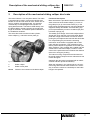
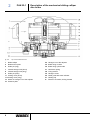
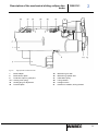
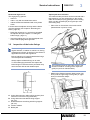
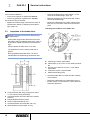
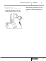
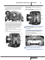
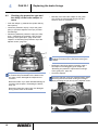
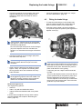
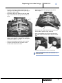
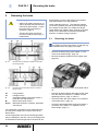
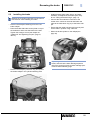
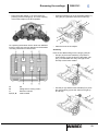
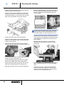
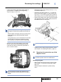
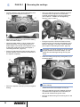
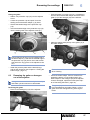
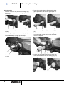
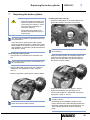
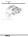
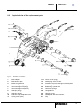
PAN 22-1
Assembly and Maintenance Instructions
PAN 22-1
Assembly and Maintenance Instructions
Edition 3
This publication is not subject to any update service.
You will find the latest version in INFORM
www.wabco-auto.com
© 2009
The right of amendment is reserved.
Version1/06.2009(en)
815 010 066 3
PAN 22-1
Table of Contents
1 Important instructions and safety instructions
5
1.1
General Information
5
1.2
Safety instructions
5
1.3
Repair and maintenance instructions
6
1.4
Symbols used
6
2 Description of the mechanical sliding calliper disc brake
3 Service Instructions
7
10
3.1
3.1.1
Checking the brake
Checking the adjuster
10
10
3.2
Inspection of the brake linings
11
3.3
Inspection of the brake discs
12
4 Replacing the brake linings
14
4.1
Removal of the brake linings
14
4.2
Checking the protection caps and the ability of the brake calliper to move
16
4.3
Fitting the brake linings
17
5 Renewing the brake
20
5.1
Removing the brake
20
5.2
Installing the brake
21
6 Renewing the sealings
22
6.1
Renewing the protection caps and the bushings of the guide pins
22
6.2
Renewing the protection cap of the adjuster screw
25
6.3
Renewing the gaiter on hexagon nut of the adjuster
27
7 Replacing the brake cylinder
29
8 Annex
31
4
8.1
Widths A/F and tightening torques
31
8.2
Exploded view of the replacement parts
33
8.3
Procurement and disposal of spare parts
34
Important instructions and safety instructions
1
Important instructions and safety instructions
1.1
General Information
This publication describes maintenance and repair of
the disc brakes PAN 22-1 including the individual
operations and work processes required to replace
components using available repair kits.
1.2
WARNING
Reduced braking effect or brake
failure
Danger of accidents
– Regularly check the wear limits of
brake linings and brake discs.
– Replace worn, scorched, glazed,
or oily brake linings immediately.
Before you begin with maintenance, repair, replacing a part etc., carefully read all the safety
instructions as well as the repair and maintenance
instructions included this publication. These instructions must be observed to avoid personal
injury or material loss.
– Immediately replace worn or damaged brake discs.
– Always replace all brake linings
and brake discs on an axle.
WARNING
Rolling vehicle
Danger of accidents
– Position the vehicle on an even
surface and secure it against rolling away with brake wedges.
Before you perform any work on the vehicle
(repair, maintenance, replacing parts, etc.),
you must ensure the following:
– Only use approved devices to jack
up and secure the vehicle.
Only trained and qualified personnel may perform
repairs on the vehicle.
– Ensure that the gearbox is in neutral and that the hand brake is applied.
Always follow specifications and instructions of
vehicle manufacturer.
Always comply with the Company and national
accident prevention guidelines and Health and
Safety regulations.
1
Safety instructions
This publication is directed at trained service
technicians employed at workshops for commercial vehicles.
WABCO only guarantees the safety, reliability and
performance of its products and systems if all
instructions, notes and safety instructions are
observed.
PAN 22-1
CAUTION
Risk of injury due to hazardous
dusts
– Do not clean any soiled areas of
the brake with compressed air or
other high-pressure devices.
Wear any necessary protective clothing.
The workplace has to be dry, as well as sufficiently lit and ventilated.
CAUTION
Risk of injury due to heavy load
– A second technician must assist
during removal and installation of
the brake.
CAUTION
Risk of injury due to brake action
while working on the brake
– Attach a clearly marked note on
the steering wheel saying that
work is being performed on the
vehicle and that the brake must
not be touched.
5
1
CAUTION
PAN 22-1
Important instructions and safety instructions
– Only grip the brake on the outside
with your hands while moving the
brake calliper or working on the
brake.
– Do not use motor-driven screw
tools.
CAUTION
Risk of injury due to falling brake
parts
– Use suitable equipment, such as a
vice, to clamp the brake when performing repairs on the brake outside the vehicle.
1.3
fied spanners, applying only the specified tightening torque; refer to the table in Annex (see chapter 8.1 "Widths A/F and tightening torques",
page 31) for the corresponding positions.
Risk of injury: Crushing of fingers
– Perform a concluding roller test stand test having
completed the repairs. If no roller test stand is
available, conduct a test drive with brake action
tests.
– Do not perform full braking, with the exception of
emergency braking, during the first 50 km after
new brake linings have been fitted. Also avoid
continuous braking over longer periods. Ensure
that the driver of the vehicle is informed.
1.4
Symbols used
DANGER
Repair and maintenance instructions
– Imminent hazard situation which
can cause serious personal injury
or death if the safety instruction is
not observed.
For good handling and braking characteristics it is
essential that the disc brake be in flawless technical
condition.
WARNING
– If cast parts have been heavily damaged or are
severely worn, (cracks for example), replace the
entire brake following the instructions.
– Potential hazard situation which
can cause death or serious personal injury if the safety instruction
is not observed.
– Do not open the clamping unit on the brake calliper, and do not unscrew the fastening screws on
the clamping unit cover.
– Do not apply the brake when brake linings have
been removed.
CAUTION
– Potential hazard situations that
can cause minor or moderate to
severe injury, or material loss, if
the safety instruction is not observed.
– Do not use compressed air or other high-pressure
devices when cleaning the brake or the vehicle.
This may result in the risk of personal injury or
hazardous dusts. Rubber parts of the brake could
also be damaged.
– Only use original WABCO parts and approved
brake linings. An exploded view of replacement
parts is found in the annex of this document (see
chapter 8.2 "Exploded view of the replacement
parts", page 33).
•
– Only use grease contained in the repair kits.
– Step
– Perform the repair work using only the recommended tools. Do not use motor-driven screw
tools. Tighten screws and nuts only with the speci-
6
Important instructions, information, or tips that you
should always observe.
List
Description of the mechanical sliding calliper disc
brake
2
PAN 22-1
2
Description of the mechanical sliding calliper disc brake
The brake PAN 22-1 is a one-piston-brake. The brake
is supposed to be used in commercial vehicles and
trailers on front and rear axles for 22.5" wheel rims as
service, auxiliary and parking brake. It is actuated
mechanically via a diaphragm brake cylinder or a
spring brake actuator. The latter is fitted directly onto
the brake calliper, thereby reducing the overall axial
length of the brake. This enables optimal utilisation of
the installation situations.
Functional description
The entire disc brake consists of brake cylinder,
brake calliper (1), and brake anchor plate (2).
The radially open design of the brake calliper allows
simple and quick changes of the brake pads. Brake
pads with a large wear volume are used in order to
prolong the pad replacement intervals with this brake.
More information is provided in the illustrations below.
Axial movement of the brake calliper (1) occurs on
the guide pins (8, 9) of the brake carrier (2). In the
brake carrier the brake pads (35, 36) are guided and
supported axially relocatable. The brake lining support is implemented by means of a retainer (38) and
hold-down springs (37).
For compensating the pad wear the actuating
mechanism of the brake is equipped with an automatic adjuster mechanism. This mechanism maintains a preset clearance regardless of load and operating conditions. This, together with a stable and stiff
construction of the brake calliper, results in a safe
control of the pedal travel and increases the distance
reserve for emergency braking.
The internal moving components are lubricated for
life and all sealing components are maintenance free
unless damaged.
fig. 2-1:
1
2
Arrow
Entire disc brake
Brake calliper
Brake anchor plate
Direction of movement of the brake caliper
Optionally the disc brake is equipped with an electrical wear indicator (threshold indicator).
When the indicators in the vehicle light up, the minimum lining thickness has been reached. It is necessary to drive the vehicle to a workshop for the brake
linings to be replaced.
7
2
fig. 2-2:
PAN 22-1
Description of the mechanical sliding calliper
disc brake
Top view and sectional view
1 Brake calliper
2 Brake anchor plate
6 Guide pin (long)
7 Internal hexagon bolt (short)
8 Internal hexagon bolt (long)
9 Guide pin (short)
11 Closing cover (short)
11.1Closing cover (long)
13 Gaiter on hexagon nut of the adjuster
19 Pressure plate
8
22
35
36
37
38
39
40
41
A
Hexagon nut of the adjuster
Brake lining rim side
Brake lining cylinder side
Hold-down spring
Lining retainer
Hexagon screw
Cable guide with wear indicator
Holding clip
Direction of rotation, driving forward
Description of the mechanical sliding calliper disc
brake
fig. 2-3:
1
2
5
11.1
12
19
PAN 22-1
2
Page preview and sectional view
Brake calliper
Brake anchor plate
Protection caps for guide pins
Closing cover (long)
Sealing plug for adjustment
Pressure plate
35
36
37
38
39
A
Brake lining rim side
Brake lining cylinder side
Hold-down spring
Lining retainer
Hexagon screw
Direction of rotation, driving forward
9
3
3
PAN 22-1
Service Instructions
Service Instructions
CAUTION
Risk of injury
– Observe all safety instructions, as
well as all repair and maintenance
instructions (see chapter 1 "Important instructions and safety instructions", page 5).
– These instructions must be observed to avoid personal injury or
material loss.
3.1
Checking the brake
– Check the gaiter (13) for wear and damage.
3.1.1
Checking the adjuster
– Renew defect gaiter (13) of the adjuster (see
chapter 6.3 "Renewing the gaiter on hexagon nut
of the adjuster", page 27).
Directions of rotation and torques of the hexagon
nut of the adjuster are listed in the table in the
annex (see chapter 8.1 "Widths A/F and tightening torques", page 31, item I).
– Use the ring spanner to turn hexagon (22) of the
adjuster ½ turns clockwise (see chapter 8.1
"Widths A/F and tightening torques", page 31,
item I)
– Remove the sealing plug (12) of the adjuster.
There must be sufficient space for the engaged
ring spanner; it must not be obstructed when it is
turned during adjustment.
When removing the sealing plug, apply the respective tool (such as a screwdriver) only to the sealing
plugs and do not damage the gaiter (13) of the adjuster or the Brake calliper.
Do not use an open-end spanner for the hexagon
(22) of the adjuster and never overstrain the
hexagon nut. Otherwise the hexagon will be damaged.
– Gently apply the brake 5 times (braking pressure
approx. 1 bar).
The adjuster is functioning when the ring spanner
turns anti-clockwise with every brake actuation.
With increasing adjustment the angle of rotation of
the engaged ring spanner becomes smaller. The
adjuster is working correctly if the ring spanner
rotates anti-clockwise as described above.
10
Service Instructions
PAN 22-1
3
Faults that might occur:
Optical pad wear indication
The engaged ring spanner
• does not
• rotate - only with the initial brake action
• rotates forward and backward with every brake
action
In these cases the adjuster is faulty and the brake
must be replaced (see chapter 5 "Renewing the
brake", page 20).
The medium brake pad wear can be measured with a
tape measure or a ruler, depending on the access,
either at the fitted pin (long guide pin at disc leading
side) or at the non-fitted pin (short guide pin at the
disc trailing side).
– Place ruler on the surface of the brake carrier.
(hatched area in picture, arrow)
– Reset the clearance to 1 mm having completed
the adjuster test (see chapter 4.3 "Fitting the
brake linings", page 17).
– Insert the sealing plug (12) into the adjuster and
ensure that the plug has a tight seat.
3.2
Inspection of the brake linings
The brake lining thickness must be checked at
regular intervals, in relation to vehicle use, during
maintenance intervals, as well as in the context of
applicable local laws and regulations.
Burned, glazed or oil contaminated brake linings
must be replaced immediately.
Always replace all brake linings on an axle.
To avoid damaging the brake disc replace the
brake linings no later than at the point when they
reach the wear limit at their weakest spot.
The measuring point on the brake carrier is the
worked on area for screwing of the respective
guide pin (arrow on hatched area).
– Measure the distance between brake carrier (left
arrow) and the upper edge of the guide pin (right
arrow) on the brake calliper.
A Lining thickness worn without lining support (limit
value 2 mm minimum lining thickness)
B Lining thickness new without lining support
(23 mm)
C Overall thickness new lining with lining support
(32 mm)
D Friction material
H Brake pad
11
3
PAN 22-1
Service Instructions
If the measured distance
• on the short guide pin is greater than 94 mm,
• on the long guide pin is greater than 120 mm,
the maximum wear is reached.
– Remove the brake linings (see chapter 4.1 "Removal of the brake linings", page 14).
– Replace the brake linings if the maximum wear is
reached (see chapter 4 "Replacing the brake linings", page 14).
– Replace the brake disc if the wear measurement
limit of 37 mm has been reached at the thinnest
point.
– Measure the brake disc thickness at the contact
area of the brake linings.
Checking the condition of the brake disc
3.3
Inspection of the brake discs
Regularly check the wear limits of brake linings
and brake discs.
When brake linings and/or brake discs are worn,
the braking effect is reduced and there is a risk of
brake failure. Replace brake discs and brake linings.
Always replace all brake discs on an axle.
The brake discs must be cleaned and free of
grease.
Having installed new brake discs, it is recommended that new brake linings be fitted as well.
A network-type cracks: permissible
B radial cracks up to a max. 0.5 mm width: permissible
C Uneven disc surface up to max. 1.5 mm depth:
permissible
D continuous cracks: not permissible
a Width of the braking area
– Check the brake disc for cracks and the condition
of the surface.
– Replace the brake disc if the brake disc has continuous cracks or unevenness or cracks reach the
maximum dimension.
A Lining thickness with lining support (limit value
11 mm minimum lining thickness)
C Overall thickness new lining with lining support
(32 mm)
D pad backplate thickness (9 mm)
E minimum pad thickness (2 mm)
F Overall thickness new brake disc (45 mm)
G Wear allowance limit (at least 37 mm)
12
Service Instructions
Checking the disc runout
– Fasten the dial indicator to the brake calliper.
– With the brake disc installed, check the disc
runout by rotating the wheel hub. Limit value:
0.15 mm
PAN 22-1
3
– Replace the brake disc or rework it appropriately if
the disc runout is greater than 0.15 mm.
– Install the brake linings, and adjust the clearance
(see chapter 4.3 "Fitting the brake linings",
page 17).
13
4
4
PAN 22-1
Replacing the brake linings
Replacing the brake linings
CAUTION
Risk of injury
– Observe all safety instructions, as
well as all repair and maintenance
instructions (see chapter 1 "Important instructions and safety instructions", page 5).
– These instructions must be observed to avoid personal injury or
material loss.
4.1
– Remove three hold-down springs (37) from the
brake linings (35 and 36) and the pressure plate
(19).
– Remove the cable guide (40) with the wear indicators.
– Remove the spring clips (41) from the calliper.
– Remove the sealing plug (12) of the adjuster from
the calliper (1).
Removal of the brake linings
– Disconnect the plug connection (40) of the wear
indicator. (40)
– Remove the hexagon head screw (39) from the
lining retainer (38) (see chapter 8.1 "Widths A/F
and tightening torques", page 31, item II).
– The lining retainer (38) has to be withdrawn from
the calliper (1).
When removing the sealing plug, apply the respective
tool (such as a screwdriver) only to the sealing plugs
and do not damage the gaiter (13) of the adjuster or
the Brake calliper.
– Check the gaiter (13) for wear and damage.
– Renew defect gaiter (13) of the adjuster (see
chapter 6.3 "Renewing the gaiter on hexagon nut
of the adjuster", page 27).
14
Replacing the brake linings
– Use a ring spanner to turn the hexagon (22) of the
adjuster clockwise to the stop position and then
turn the hexagon back in anticlockwise direction
by 90°.
– While turning the hexagon (22), use your hand to
push the pressure plate (19) towards the cylinder
side to ensure that the pin as an antirotation element for the adjuster screw (21) does not slip out
of the retaining groove of the pressure plate.
Otherwise the adjuster screw could turn and so
damage the protection cap (10).
– Push the calliper (1) towards the rim side (arrow)
by hand.
– Remove the brake lining (35) on the rim side.
PAN 22-1
4
– Push the calliper (1) towards the cylinder side
(arrow) by hand.
– Remove the brake lining (36) and pressure plate
(19) on the cylinder side.
Danger of bodily injury!
Do not apply the brake when brake linings have
been removed.
– Use a wire brush to clean pressure plate, lining
slot and pressure plate guide, and remove any
corrosion on these components.
Take care not to damage the protection caps (5,
10) while cleaning.
The guide surfaces of the brake linings on the
brake anchor plate must be free of grease!
15
4
4.2
PAN 22-1
Replacing the brake linings
Checking the protection caps and
the ability of the brake calliper to
move
– Manually move the brake calliper on the guide
pins across the entire displacement path and
check for ease of movement.
– Push the calliper (1) towards the cylinder side by
hand (arrow).
– Check the protection caps (5, 10) for the guide
pins (8, 9) and the adjuster screw (21) for wear
and damage.
– Renew any defective protection caps (see chapter 6.1 "Renewing the protection caps and the
bushings of the guide pins", page 22 and see
chapter 6.2 "Renewing the protection cap of the
adjuster screw", page 25).
Do not squeeze the guide pin protection caps
against the brake anchor plate while moving the
calliper.
– Replace the bushings and the protection caps if
the calliper moves sluggishly (see chapter 6.1
"Renewing the protection caps and the bushings
of the guide pins", page 22).
If a protection cap is damaged, check whether dirt
or moisture has penetrated into the brake's interior parts or have damaged the calliper due to
corrosion.
Renew the brake if you have identified damage or
corrosion (see chapter 5 "Renewing the brake",
page 20).
Renew the protection caps if they are damaged
during service work on the brake.
16
– Check the adjuster.
Secure the adjuster screw (21) against twisting when
performing the test and when turning the hexagon
(22) by arresting the pin (arrow) of the adjuster screw.
Replacing the brake linings
– Use the ring spanner to turn hexagon (22) of the
adjuster anticlockwise until the adjuster screw
reaches the brake disc and check for ease of
movement.
PAN 22-1
4
– Check the brake discs (see chapter 3.3 "Inspection of the brake discs", page 12).
4.3
Fitting the brake linings
– To insert the brake linings on the cylinder side,
push the calliper towards the cylinder side until
there is sufficient distance to the brake disc.
– Insert the pressure plate (19) into the brake anchor plate and push the pressure plate against the
adjuster screw (21).
There must be sufficient space for the engaged
ring spanner; it must not be obstructed when it is
turned during adjustment.
Do not use an open-end spanner for the hexagon
(22) of the adjuster and never overstrain the
hexagon nut. Otherwise the hexagon will be damaged.
– Use the ring spanner to turn hexagon (22) clockwise back to the stop limit.
When returning the hexagon (22) clockwise, the
torque is greater than the torque to turn anticlockwise.
– Gently apply the brake 5 times (braking pressure
approx. 1 bar). The adjuster is functioning when
the ring spanner turns anti-clockwise with every
brake actuation.
With increasing adjustment the angle of rotation of
the engaged ring spanner becomes smaller. The
adjuster is working correctly if the ring spanner
rotates anti-clockwise as described above.
Ensure that the pressure plate is seated in the
guide groove of the brake anchor plate and that it
rests with the entire surface on the guide strips of
the brake anchor plate. Otherwise the pressure
plate could slide out of the guiding.
If required, push the calliper a little towards the
rim side.
The pin of the adjuster screw must mesh with the
groove (small arrow) of the pressure plate, otherwise the adjustment will not function correctly.
Turn the adjuster screw until the pin meshes with
the groove of the pressure plate. Ensure that the
protection cap is not twisted.
Faults that might occur:
The engaged ring spanner
• does not
• rotate - only with the initial brake action
• rotates forward and backward with every brake
action
In these cases the adjuster is faulty and the brake
must be replaced (see chapter 5 "Renewing the
brake", page 20).
17
4
PAN 22-1
Replacing the brake linings
– Fit a new brake lining (36) on the cylinder side.
– Fit two new spring clips (41) in the brake calliper.
– Push the calliper towards the rim side until the
brake lining (36) of the cylinder side bears against
the brake disc.
– Place the cable guide (40) with preassembled
wear indicators onto the brake calliper and insert
the indicators (circle) into the brake linings.
– Fit a new brake lining (35) on the rim side.
– Adjust the clearance by means of a 1 mm feeler
gauge (arrow). For this purpose insert the feeler
gauge between the brake lining of the rim side
and the calliper. Turn the hexagon (22) of the adjuster anticlockwise with a ring spanner until both
brake linings bear on the brake disc.
Ensure that each wear side of the indicators
points towards the brake disc and that the indicators are inserted completely into the brake pad.
– Position the cable guide (40) and the cable outlet
of the wear indicators onto the brake calliper.
When laying the cable, ensure that the cable does
not touch the brake lining.
– Place the new hold-down springs (37) over the
cable guide onto the brake linings (35, 36) and the
pressure plate (19).
Always insert the feeler gauge into the centre
between brake calliper (1) and brake lining support plate (35). Do not use an open spanner for
the hexagon (22) of the adjuster. Otherwise the
hexagon will be damaged.
18
Replacing the brake linings
– Push the new lining retainers (38) through the
openings in the cable guide into the openings (arrows) of the brake calliper.
PAN 22-1
4
– Fasten the cable to the spring clip (41) of the
brake calliper.
– Press down the lining retainer so that the radial
lugs of the hold-down springs mesh with the retainer.
– Ensure that the cable has been laid correctly and
fix the cable in position using cable ties.
– Push a new sealing plug (12) into the opening of
the brake calliper. Ensure that the plug has a tight
seat.
– Fasten a new hexagon screw (39) to the brake
calliper (see chapter 8.1 "Widths A/F and tightening torques", page 31, item II).
– Remove the transport protection cap if in place.
– Connect the wear indicator connector to the
socket of the vehicle or the axle.
– Check the wheel hub for ease of movement.
Having completed the work, test the brake on a
roller test stand.
19
5
5
PAN 22-1
Renewing the brake
Renewing the brake
CAUTION
Risk of injury
– Observe all safety instructions, as
well as all repair and maintenance
instructions (see chapter 1 "Important instructions and safety instructions", page 5).
– These instructions must be observed to avoid personal injury or
material loss.
determined by means of the brake's lining retainer
(38) and hexagon screw (39) positions.
Use the following scheme: The retention aperture
for the lining retainer (38) and the thread opening for
the hexagon screw (39) in the calliper are always
offset relative to the brake centre M (axle) by an axle
offset V in the brake disc exit direction (brake disc
direction of rotation driving forward).#
5.1
Removing the brake
The graphic representation of the brake carrier
may differ from the actual design, so that the representation does only apply in principle.
– Remove the brake linings (see chapter 4.1 "Removal of the brake linings", page 14).
– Remove the brake cylinder from the calliper (see
page 29).
fig. 5-1:
Left brake with the direction of rotation of the brake
disc driving forward
fig. 5-2:
Left brake with the brake disc direction of rotation
driving forward
38
39
V
M
Arrow
Lining retainer
Hexagon screw
Axle offset relative to the brake centre in
brake disc exit side direction
Brake centre (axle centre)
Brake disc direction of rotation, brake disc
exit side top
The new brake is supplied as a pre-assembled unit
and may be mounted to the vehicle's axle via the
brake carrier.
Left and right brake must not be interchanged when
they are installed on the axle. The correct assignment
of the brakes to left and right side of the axle can be
20
– Disconnect the plug connection of the wear indicator.
– Remove the brake calliper with brake anchor plate
from the axle (see chapter 8.1 "Widths A/F and
tightening torques", page 31, item III).
– Check the brake disc (see chapter 3.3 "Inspection
of the brake discs", page 12).
– Check the dismantled brake linings and replace if
necessary (see chapter 3.2 "Inspection of the
brake linings", page 11).
Renewing the brake
5.2
Installing the brake
Observe the mounting instructions of the vehicle
manufacturer when installing the brake.
– Remove the transport fastenings from the new
brake calliper.
– Place the brake with brake anchor plate on top of
the brake disc and mount the brake to the axle.
Tighten the hexagon screw (see chapter 8.1
"Widths A/F and tightening torques", page 31,
item III).
PAN 22-1
5
– Install pressure plate, brake linings, and wear
indicators, and adjust the clearance (see chapter 4.3 "Fitting the brake linings", page 17).
– Connect the wear indicator connector to the
socket of the vehicle or the axle and fasten the
cable to the hold-down clip (41) of the brake calliper.
– Ensure that the cable has been laid correctly and
fix the cable in position using cable ties.
– Mount the brake cylinder on the calliper(see
page 29).
Depending on the installation position of the
brake, ensure that the lower drainage aperture
facing the ground is open! All other drainage apertures must be sealed by plugs.
– Remove the transport protection cap (arrow) from
the brake calliper in the cylinder fastening area.
21
6
6
PAN 22-1
Renewing the sealings
Renewing the sealings
CAUTION
Risk of injury
– Observe all safety instructions, as
well as all repair and maintenance
instructions (see chapter 1 "Important instructions and safety instructions", page 5).
– Unscrew the screws (6, 7) (see chapter 8.1
"Widths A/F and tightening torques", page 31,
item IV), and remove the brake calliper (1) from
the brake anchor plate (2).
– These instructions must be observed to avoid personal injury or
material loss.
When replacing all of the gaiters in the calliper,
the work sequences for renewing the protection
caps and the bushings of the guide pins as well
as the protection cap of the adjuster screw can be
executed combined.
6.1
Renewing the protection caps and
the bushings of the guide pins
Disassembly
– Remove brake linings, the brake cylinder, the
wear sensor, and the brake calliper with brake anchor plate from the axle (see chapter 5.1 "Removing the brake", page 20).
– Remove the closing cover (11, 11.1) of the guide
pins (8, 9) from the brake calliper (1).
When removing the sealing plug, apply the respective tool (such as a chisel) only to the closing
cover and do not damage the seat of the closing
cover on the brake calliper.
22
Danger of bodily injury!
Risk of injury due to unsecured brake calliper.
– Clean the contact areas (fitting collars) to the
guide pins on the brake anchor plate (2).
– Remove the guide pins (8, 9) from the brake calliper (1).
– Remove the protection caps (5) from the ring
groove of the Brake calliper (1).
Renewing the sealings
– Place the brake calliper (1) on a firm base for
pressing out the bushings (4). The cover opening
of the brake calliper must face upwards.
For replacing the bushes use the tools from WABCO
tool box 12 851 021 and pay attention to the detailed
mounting instructions in the tool box.
PAN 22-1
6
– Press the bushings (4) out of the brake calliper (1)
using the pin (A) and the extrusion mandril (C).
– Clean the bores in the calliper.
Assembly
Press in two new bushings for the longer guide pin.
– Use pin (A) and insert mandril (F) to press the
inner bushing (4) into the bores of the brake calliper (1) on the brake disc entry side right to the
end stop of the insert mandril.
A
B
C
D, E, F, G
Pin
Fitting tool for closing covers
Extrusion mandril
Insert mandril
– Use the pin (A) and the insert mandril (E) to press
the outer bushing (4) into the same bore right up
to end stop.
23
6
PAN 22-1
Renewing the sealings
– Grease the space between the bushings and the
sliding surfaces of the bushings.
– Use pin (A) and insert mandril (D) to press a new
bushing (4) for the short guide pin into the bores
of the brake calliper (1) on the brace disc exit side
right to the stop position of the insert mandril.
– Position the beaded edge of the protection caps (5)
into the sealing seats (ring grooves) of the guide
pins (8, 9). Ensure that the metal-ring does not
move off gaiter.
Ensure that the beaded edge of the protection
caps (5) have an even and wrinkle-free seat on
the brake calliper (1) and the guide pins (8, 9).
– Grease the sliding surfaces of the bushings.
– Clean the sealing seats (ring groove) of the brake
calliper for the protection caps. The sealing seats
must be free of grease.
– Push the new green protection caps (5) into the
sealing seats (ring groove) of the brake calliper (1).
– Remove any excess grease. The plane surfaces
of the guide pins to the brake anchor plate and the
contact areas of the brake anchor plate must be
free of grease.
– Manually move the guide pin in the bushings
backwards and forwards and check for ease of
movement.
– Grease the sliding surfaces of the guide pins (8, 9)
and the inner lip of the gaiters (5).
– Insert a new long guide pin (8) from the cylinder
side into the calliper (brake disc leading side).
– Insert a new short guide pin (9) from the cylinder
side into the calliper (brake disc trailing side).
– Slide the protection caps (5) over both guide pins.
24
– Place the calliper (1) on the brake anchor plate (2)
and the inserted guide pins (8, 9) into the fitting
collar.
– Insert new screws (6, 7) through the guide pins
inserted in the brake calliper (1). Use the long
screw (6) for the long guide pin (8) and the short
screw (7) for the short guide pin (9).
Renewing the sealings
– Fasten the screws to the brake anchor plate (2)
(see chapter 8.1 "Widths A/F and tightening
torques", page 31, item IV).
PAN 22-1
6
– Grease the bores for the closing cover (11, 11.1)
in the brake calliper (1).
– Insert the new closing covers (11, 11.1) into the
bores of the brake calliper (1). Use the long closing cover (11.1) for the long guide pin (8) and the
short closing cover (11) for the short guide pin (9).
– Press in the closing cover right up the end position
using the fitting tool for closing covers (A, B) from
the WABCO tool box 12 851 021.
On assembly ensure that the gaiters (5) are not
damaged or twisted during tightening the bolts (6,
7).
Always tighten the longer guide pin (8) with pressfit first and then the shorter guide pin (9) with
clearance.
If the guide pins (8, 9) are released from the brake
anchor plate (2) during the maintenance work,
new screws (6, 7) must be used for reassembly.
– Manually move the brake calliper on the guide
pins (8, 9) across the entire displacement path
and check for ease of movement; repeat the action a number of times.
Avoid damaging the covers while pressing them
in.
– Install the brake, brake linings and brake cylinder
(see chapter 5.2 "Installing the brake", page 21).
6.2
Renewing the protection cap of the
adjuster screw
If the gaiter is removed individually, brake calliper
and brake cylinder need not be dismantled.
Removing the gaiter
– Remove the brake linings and the pressure plate
(see chapter 4.1 "Removal of the brake linings",
page 14).
– Push the calliper towards the cylinder side by
hand.
Do not squeeze the guide pin protection caps
against the brake anchor plate while moving the
calliper.
25
6
PAN 22-1
Renewing the sealings
– Pull the protection cap (10) from the sealing seat
(ring groove) of the adjuster screw (21).
– Remove the protection cap (10) from the sealing
seat of the brake calliper.
– Check the brake calliper. If dirt or moisture has
entered the brake, or if the sealing seat in the
brake calliper or the thread of the adjuster screw
is damaged, replace the brake (see chapter 5
"Renewing the brake", page 20).
– Fit the rim side brake lining into the lining slot so
that the adjuster screw cannot be screwed out of
the adjuster completely.
– Use a ring spanner to turn the hexagon (22) anticlockwise until the adjuster screw has been
screwed outwards approx. 30 mm by this action
(see chapter 8.1 "Widths A/F and tightening
torques", page 31, item I).
– During this process, check the thread of the adjuster screw (21) for corrosion and damage. If the
thread is damaged or corroded, renew the brake
(see chapter 5 "Renewing the brake", page 20).
The gaiter (10) can be renewed, if no dirt or water
has penetrated into the brake calliper, or if the
gaiter has been damaged during servicing the
brake.
– Clean the sealing seat (arrow) of the gaiter (10) in
the brake calliper.
Ensure that no dirt or moisture enters the brake
when cleaning.
– Secure the adjuster screw (21) on the pin against
twisting.
– Grease the thread of the adjuster screw (21).
– Use a ring spanner to turn the hexagon (22) anticlockwise until the adjuster screw has been partially turned inwards through this action.
– Remove the brake lining from the lining slot on the
rim side.
26
Renewing the sealings
Fitting the gaiter
– Slide a new protection cap (10) over the adjuster
screw.
PAN 22-1
6
– Push the gaiter (13) using a tool (e.g. screwdriver)
from the seat of the brake calliper and remove the
gaiter (13) of the hexagon (22) of the aduster.
– Centre the protection cap and push it into the
sealing seat of the brake calliper (1) by hand.
– Grease the beaded edge of the protection cap
(10).
– Insert the beaded edge of the protection cap (10)
into the sealing seat of the adjuster screw (21).
– Clean the sealing seat (arrow) of the gaiter (13) in
the brake calliper.
Ensure that the cap has a correct sealing seat in
the brake calliper (1) and that the beaded edge of
the protection cap (10) has an even and wrinklefree seat in the ring groove of the adjuster screw
(21).
– Install the pressure plate and the brake linings,
and set the clearance (see chapter 4.3 "Fitting the
brake linings", page 17).
6.3
Renewing the gaiter on hexagon
nut of the adjuster
If the gaiter is removed individually, brake calliper
and brake cylinder need not be dismantled.
Removing the gaiter
– Remove the sealing plug (12) of the adjuster.
Ensure that no dirt or moisture enters the brake
when cleaning.
– Check the brake calliper. If dirt or moisture has
entered the brake, or if the sealing seat in the
brake calliper or the hexagon (22) of the adjuster
screw is damaged, replace the brake (see chapter 5 "Renewing the brake", page 20).
The gaiter (13) can be renewed, if no dirt or water
has penetrated into the brake calliper, or if the
gaiter has been damaged during servicing the
brake.
27
6
PAN 22-1
Renewing the sealings
Fitting the gaiter
– Place the mounting cap (A) onto the hexagon (22)
of the aduster and push the mounting cap right up
to the stop.
– Press the mounting sleeve (B) against the inner
gaiter lip towards, that the inner gaiter lip fit correct in the annular groove of the adjuster.
– Grease the inner lip (arrow) of a new gaiter (13)
slightly.
– Remove mounting sleeve (B) and mounting cap
(A).
– Place the gaiter (13) onto the mounting cap (A).
– Check and make sure the correct seat of gaiter
(13) in the brake calliper and annular groove (arrow) of the adjuster.
– Push the gaiter (13) by hand into the sealing seat
of the brake calliper (1) right up to the stop.
– Place the mounting sleeve (B) onto the mounting
cap (A).
28
– Push a new sealing plug (12) into the gaiter (13)
of the adjuster. Ensure that the sealing plug (12)
has a tight seat.
Replacing the brake cylinder
7
PAN 22-1
7
Replacing the brake cylinder
CAUTION
Risk of injury
Installing the brake cylinder
– Observe all safety instructions, as
well as all repair and maintenance
instructions (see chapter 1 "Important instructions and safety instructions", page 5).
– Clean the sealing area on the brake calliper and
grease the calotte in the brake lever (arrow).
– These instructions must be observed to avoid personal injury or
material loss.
Only use brake cylinders as specified by the vehicle manufacturer.
The instruction to replacing the brake cylinder
serves as general information. Observe the installation guidelines as well as instructions for testing
and installation of the brake cylinder manufacturer
and adhere it strictly.
Ensure that no dirt or moisture enters the brake
when cleaning.
Removing the brake cylinder
– Unscrew the air connection from the brake cylinder.
Ensure that the air connection of the brake cylinder is pressureless.
– Attach the brake cylinder to the brake calliper and
screw the brake cylinder manually with new fastening nuts until the brake cylinder rests against
the surface of brake calliper.
– Unscrew the brake cylinder nuts (see chapter 8.1
"Widths A/F and tightening torques", page 31,
item V).
– Remove the brake cylinder from the brake calliper.
– Screw the brake cylinder with approx. 120 Nm.
– Tighten the fastening nuts with approx. 210 30 Nm (see chapter 8.1 "Widths A/F and tightening torques", page 31, item V).
Always use new fastening nuts for the installation
of brake cylinder.
Ensure that no dirt or moisture enters the brake
when removing the brake cylinder.
Depending on the installation position of the
brake, ensure that the lower drainage aperture of
the brake cylinder facing the ground is open. All
other drainage apertures must be sealed by
plugs.
29
7
PAN 22-1
Replacing the brake cylinder
– Screw the air connection to the brake cylinder.
Observe the instructions of the manufacturer of
brake cylinder in this regard.
– Ensure that the brake hose is not twisted and
routed so that it does not rub against the other
parts.
30
– Ensure that the brake hose does not exert initial
stress on the sliding function of the brake calliper
and does not obstruct brake calliper movement.
– Check the air connection for tightness.
– Perform a function and effectiveness test of the
brake.
Annex
8
Annex
8.1
Widths A/F and tightening torques
PAN 22-1
8
Table 1 (see also drawing on the next page)
Item
Width
A/F
Hexagon screw
external
inside
Tightening torque (Nm)
Comments
I
Hexagon adjuster
8
X
–
II
Screw for lining
retainer
17
X
–
III
Observe the installation guideline of the axle or vehicle manufacturer and adhere it
Brake fastening
screwed connec- strictly.
tion
IV
Guide pin
screwed connection
14
Brake cylinder
screwed connection
24
V
1)
Designation
–
X
Direction of rotation of the hexagon
• Adjust anti-clockwise (left), maximum 3 Nm: air gap
decreases
• De-adjust clockwise (right), maximum 12 Nm: air
gap increases
30 + 15 Nm
310 ± 30 Nm
Tightening sequence for guide pins:
• 1. long hexagon socket screw (fit pin)
• 2. short hexagon socket screw (clearance fit pin)
X
–
210 – 30 Nm1)
•
Screw on the fastening nuts manually till the brake
cylinder rests against the surface.
• Tighten the fastening nuts with approx. 120 Nm.
• Tighten the fastening nuts with 210 – 30 Nm.
Use fastening nuts only once.
The tightening torques apply for original WABCO cylinders
31
8
fig. 8-1:
32
PAN 22-1
Annex
Display of positions of widths A/F and tightening torques
Annex
8.2
fig. 8-1:
1
2
4
5
6
7
8
9
10
11
PAN 22-1
8
Exploded view of the replacement parts
Illustration of a left brake
Brake calliper
Brake anchor plate
Bushes for guide pins
Protection caps for guide pins
Internal hexagon bolt (long)
Internal hexagon bolt (short)
Guide pin (long)
Guide pin (short)
Protection cap for adjuster screw
Closing cover (short)
11.1
12
13
35
36
37
38
39
40
41
Closing cover (long)
sealing plug of the adjuster
Protection cap for the hexagon of the adjuster
Brake lining rim side
Brake lining cylinder side
Hold-down springs
Lining retainer
Hexagon screw
Cable guide with wear indicator
Clip
33
8
8.3
PAN 22-1
Annex
Procurement and disposal of spare parts
Procurement of spare parts
– Identify the brake by means of the WABCO part
number.
fig. 8-1:
A
B
C
D
WABCO type plate
Vehicle manufacturer part number
Production date
Assembly number
WABCO part number
– Open INFORM at www.wabco-auto.com
– Enter the WABCO part number of the brake calliper.
– Click "Repair".
– Open the spare part sheet.
Disposing of the brake components
– Dispose of used and replaced parts in accordance
with the national and regional regulations regarding
environmental protection.
Generally brake components can be scrapped.
34
transmission automation systems supplied to the world’s leading commercial
truck, trailer, and bus manufacturers.
WABCO is headquartered in Brussels,
Belgium.
For more information, visit
www.wabco-auto.com
© 2009 WABCO All rights reserved. 815 010 066 3/06.2009
WABCO Vehicle Control Systems
(NYSE: WBC) is a leading supplier of
safety and control systems for commercial vehicles. For over 140 years,
WABCO has pioneered breakthrough
electronic, mechanical and mechatronic
technologies for braking, stability, and