1
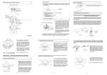
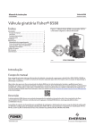
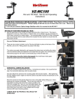
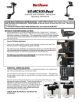
INSTALLATION, MAINTENANCE
& SERVICE BULLETIN
KT AIR SUSPENSION
(Engineering Lit. No. KL006)
KT250 T
KT300T
KT250U
KT300U
Contents
1. Preassembly Considerations
2. KT Welding Instruction – Axle Connection
o Engineering LIT No: KL004
3. KT Welding Instruction – Suspension Mounting
o Engineering LIT No: KL005
4. KT Tightening Instruction
o Engineering LIT No: KL003
Fasteners sizes and torque settings
Pivot Alignment
Height Control Valve (HCV) setting
5. Axle Alignment
6. Torque Decal
7. Maintenance
For Product Support call: (03) 9369 0000 / (07) 3372 2223 / (08) 9353 3655
www.khitch.com.au
Bulletin No: KPM-001-0712 Rev1
1
INSTALLATION, MAINTENANCE
& SERVICE BULLETIN
1. Preassembly Considerations
o Check if the correct parts have been supplied.
o Check if the installation drawings are available and match the parts.
o Check track size, axle positioning, brake booster orientation before welding.
o Ride height , hubs, wheels and tyre size need to agree with the application
o Are the correct equipment and tools available to do the installation?
o Only skilled personnel should be in charge of the installation.
o FKH KT suspension parts description:
NOTE:
See the FKH Parts View
KPS-001-1112
for all the part numbers.
For Product Support call: (03) 9369 0000 / (07) 3372 2223 / (08) 9353 3655
www.khitch.com.au
Bulletin No: KPM-001-0712 Rev1
2
INSTALLATION, MAINTENANCE
& SERVICE BULLETIN
2. KT Welding Instruction – Axle Connection
STEP 1
Weld Specification:
1. Preheat the axle connection at the axle and suspension seat if recommended.
2. Suspension welding surface must be free from grease, paint, moisture and dirt.
3. Welding parameters:
- Standard electrode: AWS E-7018 (over dried)
- Standard wire: AWS ER-70S-X
- Volts: 26-30 DCRP
- Current: 275-325 Amps
- Gas: 86%Ar, 14% CO2 at 30-35 CFH
STEP 2
Pre-weld Setup and Measurement:
1. Place the suspension on a smooth
level surface.
2. Place the axle in line with trailing arm
seat and accurately centre axle
relative to the arms.
3. Locate the camshafts in their proper
positions.
4. The arms must remain vertically
parallel to each other and square to
the axle.
5. Clamp and secure the arm assembly to the axle.
IMPORTANT:
•
Consult axle manufacturer for
preheating specifications and do
not concentrate the heat in one
area.
•
Do not over tighten clamps. The
arm pivots must remain parallel.
•
At least one side arm must seat on
the axle firmly, but non-seated side
gap must be no more than 1.5mm.
•
U-bolts should be installed after
completion of welding (allow a sufficient cool down period).
For Product Support call: (03) 9369 0000 / (07) 3372 2223 / (08) 9353 3655
www.khitch.com.au
Bulletin No: KPM-001-0712 Rev1
3
INSTALLATION, MAINTENANCE
& SERVICE BULLETIN
STEP 3
Tacking Length and Placement:
1. Tack the axle to the arm
near the centre, as
shown.
2. Double check measurement
before commencing welding.
STEP 4
Welding Direction and Sequence:
1. Start welding at rear side of
the axle connection.
2. Place four single root pass
welds at all areas.
3. Continue with second and
third weld passes.
IMPORTANT:
•
Make sure tacks are near the seat centre.
•
Make sure all 4 root pass welds are completed before proceeding to
next weld pass stage.
For Product Support call: (03) 9369 0000 / (07) 3372 2223 / (08) 9353 3655
www.khitch.com.au
Bulletin No: KPM-001-0712 Rev1
4
INSTALLATION, MAINTENANCE
& SERVICE BULLETIN
STEP 5
Welding Size and Location:
1. Perform three weld passes as shown
1st
2nd
3rd
1. Accurately perform weld passes to specified length
IMPORTANT:
•
All axle seat
connections require
three weld passes.
•
Do not wrap welds
around axle seat
corners.
CAUTION:
•
Avoid all cold laps and undercuts. Fill all craters. Clean weld between
each pass.
•
Failure to follow properly procedures can result in loss warranty
coverage.
For Product Support call: (03) 9369 0000 / (07) 3372 2223 / (08) 9353 3655
www.khitch.com.au
Bulletin No: KPM-001-0712 Rev1
5
INSTALLATION, MAINTENANCE
& SERVICE BULLETIN
3. KT Welding Instruction – Suspension Mounting
AIR SPRING MOUNTING
Mounting Plate without Spacer
Mounting Plate with Spacer
IMPORTANT:
•
Do not weld within 12mm between mating edge of the suspension component
and trailer frame.
•
It is responsibility of the suspension installer to provide both proper welding
parameters and adequate attachment for the suspension.
•
Do not attach air spring direct to trailer frame.
For Product Support call: (03) 9369 0000 / (07) 3372 2223 / (08) 9353 3655
www.khitch.com.au
Bulletin No: KPM-001-0712 Rev1
6
INSTALLATION, MAINTENANCE
& SERVICE BULLETIN
HANGER MOUTING
IMPORTANT:
•
•
Do not weld within 12mm between mating edge of the suspension
component and trailer frame.
Insure that the left and right hangers are welded on the same
perpendicular line to the chassis. (Axle alignment)
For Product Support call: (03) 9369 0000 / (07) 3372 2223 / (08) 9353 3655
www.khitch.com.au
Bulletin No: KPM-001-0712 Rev1
7
INSTALLATION, MAINTENANCE
& SERVICE BULLETIN
CROSS MEMBER MOUTING
Knee Bracket
C - Channel Bracket
IMPORTANT:
•
The above methods are common practices, but individual installations
may vary.
For Product Support call: (03) 9369 0000 / (07) 3372 2223 / (08) 9353 3655
www.khitch.com.au
Bulletin No: KPM-001-0712 Rev1
8
INSTALLATION, MAINTENANCE
& SERVICE BULLETIN
4. KT Tightening Instruction
Size: ¾-16 UNF
Torque: 55-65Nm
Size: 1-1/8-12 UNF
Torque: 1100-1200Nm
Size: M24x3
Torque: 550600Nm
Size: ¾-16 UNF
Size: 5/16-18
UNC
Torque: 15-
Size: 5/16 NUT
Torque: 35-40Nm
Size: 1/2-13 UNF
Torque: 35-45Nm
Size: 7/8-14 UNF
Torque: 600-650Nm
IMPORTANT:
•
Shock absorber fasteners must be tightened at ride height.
•
U-bolts must be tightened and torqued using a cross pattern sequence.
Ensure equal amounts of thread protrude above U-bolt nut.
CAUTION:
•
Over torque could result in fastener failure.
•
Do not apply any additional lubricants.
•
Failure to follow properly torque can result in loss warranty coverage.
For Product Support call: (03) 9369 0000 / (07) 3372 2223 / (08) 9353 3655
www.khitch.com.au
Bulletin No: KPM-001-0712 Rev1
9
INSTALLATION, MAINTENANCE
& SERVICE BULLETIN
Size: ¾-16 UNF
Torque: 55-65Nm
Size: 1-1/8-12 UNF
Torque: 1100-1200Nm
Size: M24x3
Torque: 550600Nm
Size: ¾-16 UNF
Size: 5/16-18
UNC
Torque: 15-
Size: 5/16 NUT
Torque: 35-40Nm
Size: 1/2-13 UNF
Torque: 35-45Nm
Size: 7/8-14 UNF
Torque: 600-650Nm
IMPORTANT:
•
Shock absorber fasteners must be tightened at ride height.
•
U-bolts must be tightened and torqued using a cross pattern sequence.
Ensure equal amounts of thread protrude above U-bolt nut.
CAUTION:
•
Over torque could result in fastener failure.
•
Do not apply any additional lubricants.
•
Failure to follow properly torque can result in loss warranty coverage.
For Product Support call: (03) 9369 0000 / (07) 3372 2223 / (08) 9353 3655
www.khitch.com.au
Bulletin No: KPM-001-0712 Rev1
10
INSTALLATION, MAINTENANCE
& SERVICE BULLETIN
Pivot Alignment
Inner & Outer
Collar square
holes must
line up inside
to outside
5mm rearward offset
5mm forward offset
IMPORTANT:
•
Do not fully torque up pivot bolt until Axles are fully aligned. Before
alignment, tighten up pivot bolt to a point where hardened washers can
still rotate freely.
•
Adjust all four eccentric collars to achieve Axles alignment
For Product Support call: (03) 9369 0000 / (07) 3372 2223 / (08) 9353 3655
www.khitch.com.au
Bulletin No: KPM-001-0712 Rev1
11
INSTALLATION, MAINTENANCE
& SERVICE BULLETIN
Pivot Bolt and Trailing Arm Bush
The Ø 1-1/8” bolt should be tight in the centre of the sleeve and have a gap at
each end of the sleeve.
The reason for that is that the rubber coating on the inside of the sleeve tapers
from the middle at Ø 1-1/8” out to approximately Ø 1-5/16” at each end.
The purpose of the tapered inside rubber coating, is to prevent the steel bush
rusting to the pivot bolt.
The bush (and the trailing arm) is securely locked in to position due to clamping
force of the pivot bolt after it is torqued to 1100-1200Nm.
Note: There are other trailing arm bushes, which do not have the internal rubber in the steel bush.
(W&C, Hendrickson, Aftermarket)
For Product Support call: (03) 9369 0000 / (07) 3372 2223 / (08) 9353 3655
www.khitch.com.au
Bulletin No: KPM-001-0712 Rev1
12
INSTALLATION, MAINTENANCE
& SERVICE BULLETIN
HCV Setting
Overslung at ride height.
Correct setup
Underslung at ride height.
Incorrect setup
IMPORTANT:
•
•
•
HCV can be used in right-hand or left-hand.
Unless approved by Fuwa K Hitch, DO NOT use more than one HCV per
trailer.
When assembling air fittings, be mindful that excess pipe compound or
teflon tape may contaminate the air system.
For Product Support call: (03) 9369 0000 / (07) 3372 2223 / (08) 9353 3655
www.khitch.com.au
Bulletin No: KPM-001-0712 Rev1
13
INSTALLATION, MAINTENANCE
& SERVICE BULLETIN
5. Axle Alignment
The following steps are to ensure that proper axle and suspension alignment is achieved.
•
•
•
•
•
•
Brakes must be released, pull the trailer in a straight line on a level smooth surface.
Check that the tyres are the same size and have equal inflation pressure.
Set the suspension to correct ride height.
Align all three axles within the tolerances (Fig A).
Torque pivot bolt to 1100-1200Nm
Re-check the Alignment at the 1st Service (5000-10000km or 2-4weeks)
+/- 1mm
+/- 1mm
+/- 1mm
+/- 1mm
+/- 2mm
+/- 2mm
Fig A
For Product Support call: (03) 9369 0000 / (07) 3372 2223 / (08) 9353 3655
www.khitch.com.au
Bulletin No: KPM-001-0712 Rev1
14
INSTALLATION, MAINTENANCE
& SERVICE BULLETIN
6. Torque Decal
The above Torque Decal (sticker) should be attached to the trailer chassis after it has been
painted, close to the Chassis VIN Number Decal clearly accessible and visible.
For Product Support call: (03) 9369 0000 / (07) 3372 2223 / (08) 9353 3655
www.khitch.com.au
Bulletin No: KPM-001-0712 Rev1
15
INSTALLATION, MAINTENANCE
& SERVICE BULLETIN
7. Maintenance
The maintenance frequency may need to be changed subject to application and vehicle operating
conditions.
Any instructions from the vehicle OEM must be considered first.
1.
2.
3.
4.
5.
Check all fasteners
Check U-Bolts
Check shock absorbers for leaks* and bush wear
Check HCV for leaks and correct adjustment
Check pivot bolt, TF bush and hanger wear pad
for wear and excess movement
6. Check air spring for leaks or damage
PD
PD
1st Service
1st Service
1st Service
1st Service
½ yearly
Annually
Annually
Annually
1st Service
Annually
Annually
The above recommendations are for “On Highway only” applications.
Note: * Do not confuse “misting” and “sweating” with a leaking shock absorber. Only a
leaking shock absorber needs to be replaced.
On a leaking shock absorber the oil runs all the way down the shock absorber body. If in
doubt, clean the shock absorber and check it again after a couple of days.
If you need any further information please call the relevant numbers
below or go to the FKH web site.
For Product Support call: (03) 9369 0000 / (07) 3372 2223 / (08) 9353 3655
www.khitch.com.au
Bulletin No: KPM-001-0712 Rev1
16