1
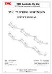
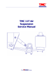
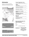
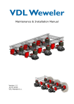
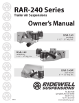
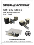
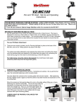
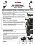
TMC Australia Pty Ltd
TMC 90 Mechanical Suspension Installation and Service Manual
TMC 90 SPRING SUSPENSION
INSTALLATION and SERVICE MANUAL
TMC AUSTRALIA PTY LTD
78 Star Crescent, P.O. Box 5028
Hallam, Victoria, 3083
2009
Telephone:
Facsimile:
E-mail:
+ (61) 3 8786 3688
+ (61) 3 8786 3699
[email protected]
Page 1 of 9
TMC Australia Pty Ltd
TMC 90 Mechanical Suspension Installation and Service Manual
INSTALLATION OF SUSPENSION HANGERS.
Position the two front suspension hangers on the trailer frame. Ensure that they are square to the frame
and located in line longitudinally and transversely. All dimensions longitudinal, transverse and diagonal
are to be within 2mm maximum variation. Position all the other suspension hangers onto the trailer
frame, ensuring all the dimensions are held to within 2mm maximum variation. On all equaliser hangers
be sure to position the hanger with the offset in the hanger to the rear. A suspension dimensional layout
drawing is supplied with each suspension kit, extra copies of the dimensional drawing can be obtained
by contacting TMC Australia Pty Ltd.
Tack weld all the suspension hangers in position, recheck the positioning of all the suspension hangers
to comply with the 2mm maximum variation before final welding of the suspension hangers.
All welding between the suspension hangers and the trailer frame is to be done using either low
hydrogen electrodes or an approved equivalent MIG process.
Weld all around the top of each suspension hanger in 12mm continuous fillet weld.
After installation of all the suspension hangers it is recommended that between all pairs of front hangers
and equalisers hangers that either a pipe or channel type cross bracing is fitted. Fully weld around the
ends of the cross bracing to each suspension hanger.
INSTALLATION OF AXLE SEATS, (Spring Seats).
Position the axle seats on the axle tube at the correct spring centres, the spring centres and suspension
hanger centres must be the same dimension. The axle seats must be located equally either side of the
axle centre. The axle seats are to be located on top of the axle for over slung suspensions and under the
axle for underslung suspensions. For cambered axle installations care must be taken to ensure the correct
positioning of the axle seats relative to the top centre mark of the axle. The axle seats must be aligned
flat and parallel to each other. Tack weld each axle seat in position and recheck the positioning of the
axle seats before final welding.
Weld the axle seats to the axle tube using either low hydrogen electrodes or an approved equivalent
MIG process.
Weld each axle seat in position using 10mm continuous fillet weld as per the welding diagram
below.
OVERSLUNG SUSPENSION
2009
UNDERSLUNG SUSPENSION
Page 2 of 9
TMC Australia Pty Ltd
TMC 90 Mechanical Suspension Installation and Service Manual
ASSEMBLY OF TORQUE ARMS
Assemble the adjustable torque arms to the same length as the matching fixed length torque arms. It is
recommended that the fixed length torque arms are fitted on the near side (kerb) of the trailer and the
adjustable torque arms are fitted on the off side of the trailer.
Fit the end of the torque arm into the suspension hanger or axle seat casting, insert the tapered rubber (or
poly) torque arm bushes in from either side. Fit the torque arm pin through the rubber bushes (or poly),
fit the torque arm washer and lock nut onto the end of the torque arm pin. Check that the torque arms are
located centrally in the end of the hanger or axle seat and tighten the torque arm pin nut.
Assembly torque.
Torque arm pins:
1”UNF nut
1”UNF nut
180/220 Nm. (Rubber bush).
250/300 Nm. (Poly bush).
Assembly Notes:
1. On two and three axle suspensions the middle and rear torque arms are longer than the torque
arm fitted to the front axle.
2. On all underslung suspensions the adjustable torque arms are to be fitted with the clamp bolts to
the top as shown on the assembly drawings.
3. On installation lubricate the rubber torque arm bushes with a soapy solution, do not use liquid
detergent or rubber grease.
4. On installation lubricate the poly torque arm bushes with rubber grease only.
FINAL ASSEMBLY
Fit the springs to the axles ensuring that the hook ends of the springs are to the rear of the axle as
installed into the suspension.
Assembly torque.
U bolts:
1”UNF nut
750/800 Nm.
Fit the axle with springs and torque arms into the hanger assemblies, ensure the spring fit up into the
hangers and equalisers, fit into the equalisers the spring drop out bolts. Tighten the torque arm pins and
drop out bolts.
2009
Page 3 of 9
TMC Australia Pty Ltd
TMC 90 Mechanical Suspension Installation and Service Manual
AXLE ALIGNMENT and ADJUSTMENT PROCEDURE
Measure from the centre of the kingpin to a centre point on each end of the front trailer axle, adjust as
needed the adjustable torque arms length to get the two dimensions equal.
Then align the remaining axles off the front trailer axle by adjusting the length of the adjustable torque
arm(s) until the axle centres on both sides of the trailer are equal.
It is possible also to do the axle alignment
using a laser or optical aligning device
designed for axle alignment.
A = B +/-2 mm
C = D +/-1 mm
E = F +/-1 mm
After the axle alignment is completed and checked tighten the adjustable torque arm clamp bolts.
Assembly torque.
Torque arm clamp bolts:
½”UNF nut
90/100 Nm.
A final visual inspection of the suspension should be carried out to ensure that all components are
correctly located and fitted. The incorrect fitment and installation of any components will greatly reduce
the service life of the suspension and its component.
ADJUSTMENT OF EQUALISER POSITION
When considering the suspension and axle to be fitted to a new trailer always take into account the angle
of slope as shown in Fig. 1. If this angle of slope is greater than that shown below for each type of
suspension in the laden condition then the equaliser will have excessive tilt (see Fig. 2). This tilt will
reduce the equaliser movement causing the equaliser to strike hanger or chassis from under uneven
(rough) road conditions.
This can be overcome by specifying a spring seat 25mm higher on the forward axle than that fitted to the
rear axle (see Fig. 3); or alternatively, by welding a 25mm thick packer to the spring seats (see Fig. 4).
The same result can be achieved by welding spacers between the main frame and the top of suspension
hanger brackets (see Fig. 5).
If the angle slope is greatly excess of the following slopes, a spring seat or packer of greater height of
25mm will be required to combat the equaliser tilt.
Tandem suspension:
One in fifty (25mm higher on front axle)
Tri-axle suspension:
One in one hundred (25mm higher on front axle, 12mm higher on
center axle)
Note: No higher spring seats or packers are necessary if the bottom of the trailer main beam and the
ground are parallel.
Tri-axle suspension: Experience has shown that the correct installation of tri-axle suspension is more
critical than that of tandem suspensions. When the trailer angle of slope in the laden condition is greater
2009
Page 4 of 9
TMC Australia Pty Ltd
TMC 90 Mechanical Suspension Installation and Service Manual
than the angle of slope specified then reduced equaliser travel will cause uneven axle loading (possibly
overloading some axles).
Overloading on some axles can cause excessive tyre wear or even failure, particularly when corning.
Therefore, it is imperative when installing tri-axle suspension that attention is paid to the laden trailer’s
angle of slope. If the slope is greater than one in two hundred, then spring seat of correct height or
packers of correct thickness must be fitted to both the front axle and center axles (the highest spring seat
or packers being fitted to the front axle).
The height of spring seat or packer can only be determined by considering each installation individually
after determining the fifth wheel height (laden), wheel base, tyre size, the trailer beam design,
suspension height (laden) etc.
When the suspension has been matched to the designed laden fifth wheel height, the recommended
variation should be within 38mm for wheel base and 50mm for the length of kingpin to center of
suspension.
TRAILER SLOPE VS. EQUALISER POSITION
Angle of Slope
Fig. 1
Fig. 2
Fig. 3
2009
Page 5 of 9
TMC Australia Pty Ltd
TMC 90 Mechanical Suspension Installation and Service Manual
Fig. 4
Fig. 5
EQUALISER BUMP STOPS (1540 SPACING ONLY)
For TMC 90 1540 axle spacing design, bump stops must be fitted at either end of all equalisers as per
below drawings. These bump stops are used for preventing damage or premature failure of hanger and
equalisers when equaliser rotate to their maximum position. This extreme position of the equalisers can
occur (lock up within the equaliser hanger) due to operations on very rough road conditions and
incorrect installation of suspension on trailer frames where trailer frame slope is not account for. The
extra load applied to the equaliser hanger and equaliser in this condition can cause damage and possibly
failure of the castings.
Please note the bump stops are welded to the trailer frame (main beam). The bump stops are not
supplied as part of the suspension kit.
FINAL INSPECTION
A visual inspection of the suspension after installation and assembly should be carried out to ensure that
all components are correctly located and seated, as incorrect location or misalignment of the components
will greatly reduce the service life of the suspension.
2009
Page 6 of 9
TMC Australia Pty Ltd
TMC 90 Mechanical Suspension Installation and Service Manual
RECOMMENDED SERVICE SCHEDULE – ON HIGHWAY
First Service 500 km or on Delivery:
Check all torque settings and re torque.
Every 5,000km:
Check all torque settings and inspect for visual damage and wear.
Grease equaliser shafts using an EP2 type grease or an approved equivalent. It is recommended
that the vehicle be lifted up to remove the load from the equalisers when greasing these points.
For vehicles operating in severe conditions it is recommended that the equaliser shafts are
greased daily.
Repair and replace parts as necessary.
Every 50,000 km or Annually:
Check all torque settings and inspect for visual damage and wear.
Check all suspension bushings for wear and deteration replace or repair as necessary.
Check all leaf springs and U bolts for wear and deteration, replace or repair as necessary.
Carry out a visual inspection of the suspension for wear and damage, repair or replace any worn
or damaged parts as necessary.
Check the axle alignment and realign as necessary. Axle alignment must be checked when ever
serve kerb contact, accident damage or the torque arm bushes are replaced.
RECOMMENDED SERVICE SCHEDULE – OFF ROAD
Daily:
Lubricate the equaliser shafts daily using an EP2 type grease. . It is recommended that the
vehicle be lifted up to remove the load from the equalisers when greasing these points.
Alternatively an automatic greasing unit can be installed to lubricate the equaliser shaft bushings.
First Service 500 km or 1 week:
Check all torque settings and re torque.
Every 5000 km or Monthly:
Lubricate as per daily.
Check all suspension bushings for wear and deteration replace or repair as necessary.
Check all leaf springs and U bolts for wear and deteration, replace or repair as necessary.
Carry out a visual inspection of the suspension for wear and damage, repair or replace any worn
or damaged parts as necessary.
Check the axle alignment and realign as necessary. Axle alignment must be checked when ever
serve kerb contact, accident damage or the torque arm bushes are replaced.
Check all torque settings.
2009
Page 7 of 9
TMC Australia Pty Ltd
TMC 90 Mechanical Suspension Installation and Service Manual
TORQUE SETTINGS CHART
U Bolts:
- 750/800 Nm. (1” UNF)
Equaliser Shaft Locknut:
- 290/350 Nm. (M30)
Torque Arm Pin Locknut:
- 180/200 Nm. (1” UNF) with rubber bushes.
- 250/300 Nm. (1” UNF) with poly bushes.
Adjustable Torque Arm Eye Bolts: - 90/100 Nm. (1/2” UNF)
Equaliser Drop Out Bolts:
- 90/100 Nm. (5/8” UNF)
As TMC Australia Pty Ltd policy is one of continuous development we therefore reserve the right
to change or modify the specifications without notification.
2009
Page 8 of 9
TMC Australia Pty Ltd
TMC 90 Mechanical Suspension Installation and Service Manual
TMC 90 Mechanical Suspension Spare Parts Listing:
Item
1.
2.
3.
4.
Part No.
324101
324102
324103
324110
324111
5. 324112
324113
324114
6. 324118
324119
7. 323143/410
323157/420
323158/430
8. 324104
324105
9. 324106
10. 324107
2009
Description
Front hanger
Rear hanger
Equaliser hanger
10 leaf spring
11 leaf spring
Axle seat 152 dia x 25 high
Axle seat 150 sq x 25 high
Axle seat 127 dia x 25 high
Spring top plate 127 axle
Spring top plate 152 axle
U bolt – 127 dia x 410
U bolt – 152 dia x 420
U bolt – 150sq x 430
Equaliser 1300 spacing
Equaliser 1540 spacing
Equaliser shaft assembly
Equaliser bush
Item
11.
12.
13.
14.
15.
16.
17.
18.
19.
20.
21.
22.
23.
Part No.
324108
323100/380
323100/495
323100/616
323124L
323124R
323133/01
323133/02
323124/04
323131
323128
323128PB
Description
Equaliser bush seal
Fixed torque arm – 380mm
Fixed torque arm – 495mm
Fixed torque arm – 616mm
Adj torque arm end – LH
Adj torque arm end – RH
Adj torque arm screw
Adj torque arm screw
Adj torque arm screw
Torque arm pin assembly
Torque arm bush – rubber
Torque arm bush - poly
9HB1/2UNC2.00 Hex bolt ½”unc x 2” long
9LN1/2UNC Nyloc nut ½”unc
9HB5/8UNC6.00 Hex bolt 5/8”unc x 6” long
9LN5/8UNC Nyloc nut 5/8”unc
Page 9 of 9