1
VTM-100
Television Signal Monitor
Installation and Operation Handbook
TWO-YEAR LIMITED WARRANTY
Videotek, Inc. warrants that this product is free from defects in materials and workmanship for a period of two years from the date
of purchase, except for CRTs and LCDs, which are warranted for a period of one year. During this warranty period, Videotek will,
at its option, repair or replace defective products at no charge for the parts or labor. Batteries are not covered in the warranty.
For warranty service or repair, this product must be returned to a service facility designated by Videotek in the original packing or
its equivalent. The purchaser shall insure the product and prepay shipping charges to Videotek, and Videotek shall insure the
product and pay shipping charges to return the product to the purchaser.
The foregoing warranty shall not apply to defects or damage resulting from improper or inadequate maintenance by the
purchaser, connecting the product to incompatible equipment, misuses, operation outside any environmental specification for the
product, improper site preparation or maintenance, or attempts by personnel other than authorized Videotek representatives to
repair or service the product.
No other warranty is expressed or implied. Videotek specifically disclaims the implied warranties of merchantability and fitness for
a particular purpose. The remedies provided by the foregoing warranty are the purchaser's sole and exclusive remedies.
Videotek shall not be liable for any direct, indirect, special, incidental or consequential damages, whether based on contract, tort,
or otherwise.
Printed October 2006
Item #061730 Rev. D
Copyright © 1994 - 2006 by Videotek, Inc.
All rights reserved.
Contents of this publication may not be reproduced in any form without permission of Videotek, Inc.
This instrument, in whole or in part, may be protected by one or more US (US Patent 6,069,607) or foreign patents or
patent applications.
Specifications subject to change without notice.
___________________________________________________________________________________________________________
Videotek and the Videotek logo are registered trademarks of Videotek, Inc.
Blank Page
Table of Contents
OPERATOR'S SAFETY SUMMARY . . . . . . . . . . . . . . . . . . . . . .
4
SPECIFICATIONS . . . . . . . . . . . . . . . . . . . . . . . . . . . . . . . . . . . . .
5
INSTALLATION OF THE VTM-100 . . . . . . . . . . . . . . . . . . . . . .
6
VTM-100 FULL MENU SYNOPSIS . . . . . . . . . . . . . . . . . . . . . . .
8
OPERATING INSTRUCTIONS . . . . . . . . . . . . . . . . . . . . . . . . . . .
User-Interface Controls . . . . . . . . . . . . . . . . . . . . . . . . . . . . .
Screen Overview . . . . . . . . . . . . . . . . . . . . . . . . . . . . . . . . . .
Default Values . . . . . . . . . . . . . . . . . . . . . . . . . . . . . . . . . . . .
Graticules and Measurement Scales . . . . . . . . . . . . . . . . . . .
Operating the VTM-100 From a PC . . . . . . . . . . . . . . . . . . .
Computer Command Summary . . . . . . . . . . . . . . . . . . . . . . .
9
9
9
16
16
19
20
TROUBLESHOOTING . . . . . . . . . . . . . . . . . . . . . . . . . . . . . . . . . . 23
ADDENDUM . . . . . . . . . . . . . . . . . . . . . . . . . . . . . . . . . . . . . . . . . 25
3
OPERATOR'S SAFETY SUMMARY
Refer all servicing to qualified service personnel
To maintain and to ensure safe operation, observe the following instructions, symbols and precautions.
1. When the unit is to be permanently cabled, first connect protective ground conductor before making any other
connections.
2. Built-in units should only be operated when properly fitted into the system.
3. For permanently cabled units without built-in fuses, automatic switches or similar protective facilities, the AC supply
line shall be fitted with fuses rated to the units.
4. Before switching on the unit, ensure that the operating voltage of the unit matches the line voltage.
5. Units of protection class I with disconnectable AC supply cable and plug may only be operated from a power
socket with protective ground contact.
a. The protective ground connection should not be made ineffective by an extension cable.
b. Any breaking of the protective ground conductor within or outside of the unit or loosening of the protective
ground connection may cause the unit to become electrically hazardous.
c. The protective ground conductor shall not be interrupted intentionally.
6. Before opening the unit, isolate it from the AC supply.
a. Adjustments and replacement of parts as well as maintenance and repair should be carried out only by
qualified personnel.
b. Observe safety regulations and rules for the prevention of accidents.
c. Use only original parts for replacing parts relevant to safety (e.g. power on/off switches, power transformers
or fuses).
7. Operator replaceable fuses may be hazardouss live. When replacing fuse, turn unit off by isolating it from the AC
supply.
8. Also observe the additional safety instructions specified in this manual.
Explanation of Symbols Used
Read Operator's Handbook and Service Manual; observe the safety symbols used.
Protective ground connection
Use of Cleaning Solvents
Cleaning of the equipment with isopropyl alcohol or similar solvents may cause degradation of labels. Use caution
when cleaning so that labels are not removed.
Fuse Information
The fuse located in the rear AC connector is of the following type and rating:
Type T (time lag) 1A 250V
The fuse located on the power supply is of the following type and rating:
Type T (time lag) 2.5A 250V
4
SPECIFICATIONS
GENERAL
OUTPUTS
VIDEO : Two 75S BNC video outputs. In component mode, output is "Y" or green channel with selected displays.
STANDARDS : NTSC/PAL (Auto Detect)
FORMATS : Composite/Component
DISPLAY WAVEFORM ACCURACY : ± 1% @ 1V
POWER REQUIREMENTS
VIDEO RESPONSE : 25Hz - 6 MHz ± 1% of 50 kHz
POWER SOURCE : 115-240V AC, 50-60 Hz
CHROMA FILTER RESPONSE : Within 3% of flat @ 3.58 MHz
and 4.43 MHz
POWER CONSUMPTION : 35 Volt amps typical
TRANSIENT RESPONSE : Preshoot and/or overshoot # 1%
TIME BASE MODES :
Line Rate: 1H, 2H, 3H
Rate: 1V, 2V, 3V
x5, x10, x20 relative to 1H or 1V
ENVIRONMENTAL
Field
Sweep Mags:
OPERATING TEMPERATURE : 0EC to 50EC
STORAGE TEMPERATURE : [40EC to 65EC
INPUT GAIN RANGE : Fully adjustable from 50% to 500%
TRANSPORTATION : 24" impact drop
COMPONENT FORMATS : GBR, BETA 75% and 100%, MII
75% and 100%, SMPTE, EBU 75% and 100%, YC using YC-1
adaptor option
HUMIDITY : 90% (non-condensing)
ALTITUDE : Operating: to 10,000 ft.
Non-operating: to 50,000 ft.
COMPOSITE VECTOR ACCURACY : ± 1E
COMPOSITE VECTOR PHASE CONTROL : > 360E, continuously variable
MECHANICAL
SC/H PHASE MEASUREMENT ACCURACY : ± 5E @ SC/H 0E
CABINET : Height: 1.75" (4.5cm)
Width: 19" (48.3cm)
Depth: 16" (40.6cm)
MEMORY : 5 user-defined setups, with total instrument settings
DISPLAY : Input displays, graticule and background colors are
user-selectable
WEIGHT : 15.0 lb (6.8kg)
INTERFACE
INPUTS
REMOTE CONTROL : RS-232 port for control by remote computer, or Microsoft or Logitech mouse
VIDEO : Three BNC loop-thru NTSC/PAL composite or one
component video input into 75S load, sync negative
VIDEO LEVEL : 1V p-p ± 6 dB
ACCESSORIES
VIDEO RETURN LOSS : $ 50 dB, DC [ 5 MHz
Operator's Handbook (with Quick Reference Card), power cord,
terminator, rackmounting hardware
EXTERNAL REFERENCE : 286 mV NTSC, 300 mV PAL SYNC
and BURST ± 6 dB
AUDIO : Two balanced stereo pairs using push-on connector
(provided)
OPTIONS
AUDIO LEVEL : 0, +4, +8, +12 dBm (menu selectable)
Service Manual
Specifications subject to change without notice.
5
INSTALLATION OF THE VTM-100
Inspect the shipping box of the VTM-100 prior to installation. Report any external or subsequent internal
shipping damage to your shipper. The box contains the VTM-100, an operator's handbook with quick reference card, one 75S terminator, a power cord, rack mounting hardware, and your warranty registration card.
The audio input connector on the rear panel has a mating connector attached to the input connector.
Rack mount the VTM-100 with the enclosed rack mounting rear support rails. The ideal installation would
leave 1 rack unit (1.75") of rack space above and below the unit; this is not required, but it is suggested.
Insure that air flow around ventilation holes on top and sides of the chassis and from the back panel cooling
fan is not obstructed when mounting.
Connect 1 composite video signal to input A and terminate that input with a 75S load (one terminator is
provided). Connect more video inputs, as your system requires, in a similar fashion, always checking that all
inputs are properly terminated. If your system uses component video (GBR or Y, B-Y and R-Y, or similar),
then connect the three inputs as labeled on the rear panel. Input A is for G or Y, input B is for B or B-Y, and
input C is for R or R-Y. For YC systems, connect Y to input A, C to input B and composite video to input C
and loop through to the External Reference input. Use of the external reference connection is otherwise
optional, and should be used where the system requires an external reference.
Connect up to two stereo pairs to the audio input connector. The input is balanced and can be set for 0,
+4, +8 or +12 dBm nominal input levels. The input is high impedance, so it may be bridged or terminated as
your system requires.
The two video output connectors function identically. They provide two outputs of the VTM-100 for viewing
on a picture monitor. The displays and menus of the VTM-100 are presented on these video output
connectors. Connect and terminate at least one output to a convenient monitor for use in the operation of the
unit. If the other output is not used, it does not need to be terminated.
If a PC or a mouse is to be used with the system, then connect either the PC or a mouse to the RS-232
port. A PC will require a null modem cable and a terminal control program such as ProComm for proper
operation with the VTM-100. The configuration of the mouse or the PC is described on page 14 under the
Control Menu section.
Connect the power cord to the AC input and connect to a properly grounded outlet. The VTM-100 will
automatically adjust to any AC input from 90 to 260V, 50 or 60Hz.
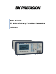
VTM -10 0
TELEVISION SIGNAL MONITOR
EXIT
SELECT
POWER
Front Panel
AC POWER
INPUT
A
B
C
Y (G)
B -Y ( B )
R-Y ( R )
AUDIO
EX REF
VIDEO OUT
1R
RS -232
H
L
1L
G
H
L
2R
G
H
L
2L
G
H
L
G
T
1A 250V
5 x 20 mm
INPUT :
115 -240V ~
50 - 60Hz
INPUT A
75
LOOP -THRU
INPUT C
75
LOOP -THRU
INPUT B
75
LOOP -THRU
DUAL STEREO
INPUT CONNECTOR
75 VIDEO
OUTPUTS
EXT. REF.
75
LOOP -THRU
RS-232 MOUSE/REMOTE
CONTROL CONNECTOR
(see p. 20 for connections)
BACK PANEL
6
FUSE
LOCATION
COOLING
FAN
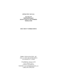
CONNECTING A Y/C SIGNAL
The VTM-100 can display a Y/C signal in composite mode (not component mode) by following the steps and
diagram shown below. Note that a composite signal must be available to use as a reference. The
interconnection shown below allows the user to view not only the Y and C sources but also the composite
waveform and vector (on the C input to the VTM-100). Insure that the composite input is connected to the C
input on the VTM-100, looped through to the External Reference input, and terminated with 75S.
From the VTM-100 menu, select NTSC (composite) on the SETUP/VID FORMAT menu. Next, select A and
B inputs with FLat filters and parade mode on the INPUT menu. Finally, select External Reference on the
INPUT menu. The monitor will then display Y (luminance) on Input A followed by C (Chroma) on Input B.
75
TERMINATORS
VTM -100
A
B
C
Y (G)
B -Y ( B )
R-Y ( R )
AUDIO
EX REF
VIDEO OUT
1R
RS -232
H
L
1L
G
H
L
2R
G
H
L
2L
G
H
L
G
T
1A 250V
5 x 20 mm
INPUT :
115 -240V ~
50 - 60Hz
SHORT
LOOP
Y
C
C
O
M
P
O
S
I
T
E
COLOR
MONITOR
TYPICAL Y/C
TAPE MACHINE
Note: If your Y/C source does not have BNC connectors, an optional YC-1 adaptor kit is available from
Videotek.
7
VTM-100 FULL MENU SYNOPSIS
VTM -100 Full Menu Synopsis
INPUT
A (G, Y)
B (B, B -Y)
C (R, R-Y)
Flat
Low pass
Chroma
Ext Ref
Parade
Overlay
Bowtie
Cal
DISPLAY
SETUP
Waveform
Vector
Audio 1
Audio 2
H/ V Sweep
Vid Format
NTSC
PAL75
PAL100
GBR
Beta75
Beta100
MII75
MII100
SMPTE75
SMPTE100
H Mag
x1
x5
x 10
x 20
Gain
Aud Level
+ 0 dBm
+ 4 dBm
+8 dBm
+12 dBm
100 %
Wfm Pos
Screen
Disp color
Color set
Grat color
Color set
Bkgd color
Color set
Grat overlay
Persistence
Infinite
Increase
Decrease
Reset
Picture Mix
0 -100 %
Intensity
Increase
Decrease
Reset
center
Vec Pos
center
phase cw
phase ccw
NTSC Ovl
Line Sel
On/ Off
Odd / Even
Line up
Line down
Control
Sensitivit y
1-10
Cursor Wrap
On/Off
via None
via Mouse 1
via Mouse 2
via Computer
Disp Mode
Full
Top
Bottom
Alarms
Sync amp
+/- 5%, 10%, 15%
Burst amp
+/- 5%, 10%, 20 %
SC/H
+/- 10˚, 20˚, 40˚
8
MEMORY
EMPTY
EMPTY
EMPTY
EMPTY
EMPTY
STORE
A-Z, 0 -9, etc.
DONE
ABORT
ERASE
OPERATING INSTRUCTIONS
The VTM-100 provides a rasterized output waveform/vector/audio display with an on-screen menu system
for operator control and setup of the unit. These controls allow for selection of inputs, filters, display parameters, video formats, and access to memory for storage and recall of user-defined setups.
User-Interface Controls: Front Panel Buttons/Joystick or Mouse
The VTM-100 can be operated directly by using the front panel push buttons and joystick, by a user-provided mouse, or with ASCII input from a remote terminal. On the front panel the left push button, marked
SELECT, enables the menu system, chooses lower level menus, and selects items. The right push button,
marked EXIT, moves to upper level menus or removes the menus completely from the display. The joystick
controls cursor movements through the menu. Moving the joystick causes the cursor to move in a
corresponding direction; for example, up or down through a menu. At the top menu levels, moving the joystick
left or right moves the cursor from one menu to the next.
A two or three button serial mouse can also be used to control the VTM-100. The use of a mouse is identical to the push buttons and joystick of the front panel. The left mouse button is the SELECT function; the
right mouse button is the EXIT function; and moving the mouse up, down, left, or right is identical to the
joystick movements. On a three button mouse, the middle button is not used.
Screen Overview
STATUS BAR
MENU
QUICK
ACCESS
MENU
DISPL AY
VIDEOTEK
SAFE AREA INDICATOR (4 PL ACES)
INDICATOR BAR
Figure 2
The VTM-100 display on your monitor is divided into four major sections: Status Bar, Indicator Bar, Display,
and Menu.
STATUS BAR - found along the top of the display. Indicates selections that the user has made, which
include:
Input and filter - up to three inputs can be selected along with three filters. In composite format,
these are indicated by input (A, B, or C), a colon (:), and the filter (Flat, Lowpass, or Chroma). In
GBR format, inputs are labeled G, B, R, and in other component formats they are labeled Y, B-Y,
R-Y. No filters are available in component formats.
Reference - the reference is indicated as either one of the three input channels (A, B, or C) or the
External reference input. In component format, the reference is either G, Y, or External.
Sweep mode and magnification - indicates whether waveforms are displayed in Horizontal (line) or
Vertical (field) and the magnification (x1, x5, x10, or x20).
Gain - indicates the Gain as a percentage of full scale.
Scale - represents the time between major divisions of the waveform graticule, based upon the
number of inputs displayed and current horizontal magnification.
9
INDICATOR BAR - provides the user with the following information:
NTSC, PAL, or selected component standard - based upon the input signal on the reference input,
and the menu selected standard.
Line number and odd or even field - when line select mode is invoked.
SCH phase - when selected the SC/H phase of the first selected input is calculated and presented
to the user in degrees and is available in composite mode only.
Burst alarm Error - if burst amplitude falls outside the user-defined limits.
Sync alarm Error - if sync amplitude falls outside the user-defined limits.
Alarm off - is indicated when no alarms are enabled.
DISPLAY - the major portion of the screen area where waveforms, vectors, and audio levels appear along
with their corresponding graticules.
MENU - is composed of two major portions: Quick Access Menu and Full Menu.
Quick Access Menu - provides easy access to the control of the most common functions on a standard waveform monitor and vector scope.
Full Menu - as shown in diagram on page 8 provides complete access to all of the VTM-100 features.
Details of each feature and how it is selected are discussed in the following sections. Depending on
modes selected, certain items on the menu are not selectable and are displayed dimly on the menu.
The menu also indicates selected items (when appropriate) by prefixing a bullet (!) in front of the
item.
Quick Access Menu - provides the ability to change:
! Waveform position - left, right, up, or down.
! Vector position - left, right, up, or down.
! Gain - up or down.
! H Mag: x1, x5, x10, or x20 - up for increased mag, down for decreased.
! Vector phase - right for clockwise, or left for counter-clockwise.
! Intensity - up or down.
! Line number - up or down, when in Line Select mode.
! Persistence - up for infinite, down for normal, when in Line Select mode.
When the Full Menu has not been invoked, pushing the EXIT button or right mouse button cycles through
these Quick Access Menu items. The joystick or mouse movement then effects the desired change. Only
those functions relevant to the currently selected display modes will be available when cycling through the
Quick Access Menu options.
Full Menu - The SELECT button in combination with the joystick (or mouse) provides access to the Full Menu.
The SELECT button gains access to a lower level menu and chooses or toggles the item highlighted. The
EXIT button moves back up the menu levels. The EXIT button may be pressed repeatedly to clear all levels
of menus from the screen. To use the Full Menu, press SELECT once. A menu bar will appear at the top of
the screen, consisting of four main menu items, Input, Display, Setup, and Memory. To access the functions
of one of these menus, move the cursor left or right to highlight the desired menu title and press SELECT.
A drop-down menu will appear, and the cursor will move down to the last valid selected menu item on the list.
When finished with a menu, continually press EXIT until all menus, including the top menu bar, have been
removed from the screen. The content of each main menu, along with corresponding submenus, is described
below.
Input Menu - The Input menu allows for selection of one to three inputs each with their own composite
filter (flat, low pass or chroma). The External Reference also may be toggled. Display of multiple inputs
in either Parade or Overlay mode is also accomplished from this menu. For component video, a Bowtie
display mode (A-B, A-C) can be selected. Finally, a calibrated 1V peak-to-peak square wave may be
selected. To access any of these functions, move the cursor to Input on the menu bar and press
SELECT. A menu with the following options will appear:
I.
Input signal: One to three input signals [ (A, B, C), (G, B, R), or (Y, B-Y, R-Y) ] can be selected. A filter
(Flat, Lowpass, Chroma) may be selected when working with composite signals. To select any of the
three inputs, move the cursor to the desired input and press SELECT. The chosen input appears on the
Status Bar along with the default filter (Flat). To change the filter of a composite signal, move the cursor
to the desired filter and press SELECT. To select an additional input, move the cursor to the desired input
10
and press SELECT. If three inputs have already been chosen, the new selection will become the first and
only input displayed. To change the filter of the additional input, move the cursor to the desired filter and
press SELECT. If the operator wishes to change previously selected inputs or filters, continue selecting
additional inputs until only one is displayed.
A.
External Reference: The reference signal for the display can be toggled between internal or external
reference input. For composite formats, the internal reference is the first input selected, while in
component it is either the Y or G channel. To select the external reference, move the cursor to Ext
Ref on the menu and press SELECT. To return to internal reference, press SELECT again while the
cursor is on the Ext Ref item. The current reference is displayed on the Status Bar.
B.
Parade/Overlay: Two or three inputs and filter combinations can be either displayed in a parade
mode or overlay mode. To select parade mode, move the cursor to Parade and press SELECT.
To select the overlay mode, move the cursor to Overlay and press SELECT.
C.
Bowtie: When a component video format is selected, a bowtie display may be viewed. To select the
Bowtie, move the cursor to Bowtie and press SELECT.
D.
Cal: Selecting Cal will toggle between the normal display and a 1V p-p square wave. To display the
Cal pulse, move the cursor to Cal and press SELECT. To turn off the square wave and return to
normal display, press SELECT again. No other display modes are available when Cal mode is
selected.
Display Menu - allows the user to:
!
!
!
!
!
Select a waveform, vector or audio display.
Change the horizontal magnification, vertical gain, position, or phase of the display.
Enable the line select mode to view a single line in odd or even fields.
Change the display mode between full screen or quarter screen (top or bottom).
Modify the vector display for a PAL input to NTSC overlay format.
To access any of these functions, move the cursor to Display and press SELECT. A menu with the
following options will appear:
A.
Waveform/Vector/Audio: A display on the monitor may consist of a waveform only, vector only or
audio only, or combinations of waveform and vector, or waveform and audio. Selection of the desired display is performed by moving the cursor to a display type and pressing SELECT. To view
a combo display, select a second display type. For example, to display a combo waveform and
vector, move the cursor to Waveform and press SELECT, then move the cursor to Vector and press
SELECT. To turn off a display type, move the cursor to that menu item and press SELECT. Note
that a vector and audio display cannot be viewed simultaneously. Selecting vector will turn off any
audio displays, and choosing an audio display will turn off the vector display.
B.
H/V Sweep: Horizontal or Vertical Waveform Sweeps may be selected by moving the cursor to H/V
Sweep and pressing SELECT. The current sweep mode is indicated by the letters "H" or "V" on the
Status Bar. Pressing SELECT with the cursor on this item will toggle the display between the two
modes.
C.
Horizontal Magnification: Waveform inputs may be displayed in four horizontal magnification modes:
x1, x5, x10, and x20. To change the magnification, move the cursor to H Mag and press SELECT.
A submenu showing the magnification factors will appear. Move the cursor to the desired
magnification and press SELECT. The display will be updated and the new magnification factor and
graticule timebase will be shown on the Status Bar. Press EXIT to remove the H Mag menu from
the screen.
D.
Gain: The gain of the waveform/vector inputs may be changed by moving the cursor to Gain and
pressing SELECT. A submenu will appear with three position selections: increase the gain (8), decrease gain (9) or set gain to 100%. The gain is variable, in 1% steps, from 50% to 500%. The gain
affects both the waveform and the vector displays. To increase the gain, move the cursor to 8 and
hold down the SELECT button. The button has ballistics, i.e., the rate of increase in gain accelerates
the longer the button is held down. To decrease the gain, move the cursor to 9 and hold down
SELECT. Move the cursor to the 100% item and press SELECT to set the gain back to its nominal
calibrated value. Press EXIT to remove the Gain menu from the screen.
11
E.
Waveform Position: The waveform position can be moved up (8), down (9), left (7), right (6), or to
a nominal center point (center) by moving the cursor to Wfm Pos and pressing SELECT. A submenu menu will appears listing the position options. Move the cursor to the direction desired and
press SELECT. If SELECT is held down, waveform movement accelerates. Press EXIT to remove
the Waveform Position menu from the screen.
F.
Vector Position: The vector position can be moved up (8), down (9), left (7), right (6), or to a nominal
center point (center), and the phase can be rotated either clockwise (phase cw) or counterclockwise
(phase ccw) direction. The selection is identical to the waveform movement. Move the cursor to
Vec Pos and press SELECT. A submenu will appear listing the movement options. Move the cursor
to the desired action and press SELECT. If SELECT is held down, the vector movement
accelerates. Press EXIT to remove the Vector Position menu from the screen.
G.
NTSC Overlay: To display PAL vectors in NTSC overlay mode, move the cursor to NTSC Ovl and
press SELECT. To deselect this mode move the cursor to NTSC Ovl and press SELECT.
H.
Line Select: A full-field single line display of either the odd or even fields is available. To select this
option, move the cursor to Line Sel and press SELECT. A submenu will appear. Move the cursor
to On/Off and press SELECT again to turn on line select. To choose a particular field, move the
cursor first to the Odd/Even item and press SELECT to toggle between odd and even fields. The
Indicator Bar at the bottom of the screen indicates whether Odd or Even is selected. To change the
line number, move the cursor to either Line 8 or Line 9 and press and hold SELECT to change the
line number. The currently selected line number is displayed on the screen along the Indicator Bar.
Press EXIT to remove the Line Select menu from the screen. Note: Line select displays the
selected line for the first input only, and alarms are turned off when line select mode is enabled.
I.
Display Mode: Input signals may be displayed as either full screen waveform/vector/audio displays
or quarter screen displays (waveform and vector, either top or bottom) with the picture of the
reference input displayed behind the waveforms. To change the display mode, move the cursor to
Disp Mode and press SELECT. A submenu will appear, listing three choices: Full screen display,
quarter screen display with the waveforms placed near the Top, or quarter screen display with the
waveforms placed near the Bottom. Move the cursor to the desired selection and press SELECT.
The display mode changes immediately. Press EXIT to remove the Display Mode menu from the
screen.
Setup Menu - allows the user to select the input video format and the audio level, modify screen display
colors (graticule, signal, and background), change the signal persistence and intensity, adjust the picture
mix, configure mouse and remote computer communication, and set up alarms. To access any of these
functions, move the cursor to Setup and press SELECT. A menu with the following options will appear:
A.
Video Format: The user may select the desired input format - either composite (NTSC, PAL75,
PAL100 depending on autodetect of field rate) or a number of standard component formats (GBR,
Beta75, Beta100, MII75, MII100, SMPTE75, SMPTE100, EBU75, EBU100). To choose a format,
move the cursor to Vid Format and press SELECT. A submenu will appear listing possible video
formats. Move the cursor to the desired format and press SELECT again. The input format changes
immediately. Press EXIT to remove the Video Format menu from the screen. Note: Field rate in
composite (NTSC/PAL) or component (50/60 Hz) is always automatically detected by the VTM-100.
B.
Audio Levels: The user may select the nominal audio input level for both audio input channels. The
nominal value is then reflected by the center line on the audio graticule. To select an audio input
level, move the cursor on the SETUP menu to Aud Level and press SELECT. The submenu will
appear listing four nominal input levels, 0 dBm, +4 dBm, +8 dBm, and +12 dBm. Move the cursor
to the desired input level standard for your application and press SELECT. Press EXIT to remove
the Audio Level menu from the screen.
C.
Screen parameters: The user may change the output display characteristics, which include display
color, graticule color, background color, graticule overlay, persistence, picture mix, and intensity. To
change any of these settings, move the cursor to Screen and press SELECT. A submenu with the
following options will appear:
12
D.
1.
Display color: To change the signal display color, move the cursor to Disp color and press
SELECT. A submenu will appear, listing fourteen color selections. Move the cursor to the desired color and press SELECT. The color of the displayed signal changes immediately. Depending on the color selected, the user may wish to make changes to intensity and persistence
as well. Note: Red is reserved for alarm indication. Press EXIT to remove the Display Color
menu from the screen.
2.
Graticule color: To change the graticule color, move the cursor to Grat color and press
SELECT. A submenu will appear, listing fourteen color selections. Move the cursor to the desired color and press SELECT. The color of the graticule changes immediately. Press EXIT
to remove the Graticule Color menu from the screen.
3.
Background color: To change the background color, move the cursor to Bkgd color and press
SELECT. A submenu will appear, listing fourteen color selections. Move the cursor to the
desired color and press SELECT. The color of the background changes immediately. Press
EXIT to remove the Background Color menu from the screen.
4.
Graticule Overlay: Unlike traditional waveform/vector scopes, the graticule on the VTM-100 is
drawn electronically and therefore can appear in front of or behind the signals displayed. To
toggle between these two settings, move the cursor to Grat overlay and press SELECT.
5.
Persistence: Persistence controls how rapidly the intensity of signal pixels decay over time. Infinite persistence provides no decay. There are seventeen persistence settings, the highest persistence being infinite; line select mode has only two, infinite and nominal. To change the persistence, move the cursor to Persistence and press SELECT. A submenu will appear. To increase the persistence, move the cursor to Increase and press SELECT, and the persistence
will be increased. To lower the persistence, move the cursor to Decrease and press SELECT,
and persistence will be decreased. To set the persistence to infinite, move the cursor to Infinite
and press SELECT. This will cause an accumulation of pixels on the display, which will remain
until another change in persistence is made. To set the persistence to the default value, move
the cursor to Reset and press SELECT. Press EXIT to remove the Persistence menu from the
screen.
6.
Picture Mix: The user may select the relative mix of background picture (the reference input as
indicated on the Status Bar) and the displayed signals and graticule. The relative ratio of each
is on a scale from 0% to 100%. A 0% selection is all signal and graticule display and no picture.
A 100% selection is all picture and no signal or graticule display. To change the picture mix,
move the cursor to Picture Mix and press SELECT. A submenu will appear listing a percentage
of picture mix ranging from 0% to 100% in 10% increments. A bullet in front of one of the
selections indicates the current ratio. To change the mix, move the cursor to the desired value
and press SELECT. Press EXIT to remove the Picture Mix menu from the screen.
7.
Intensity: To change the overall signal intensity, move the cursor to Intensity and press
SELECT. A submenu will appear. To increase the intensity, move the cursor to Increase and
press SELECT. Hold down SELECT to increase the intensity further. To lower the intensity,
move the cursor to Decrease and press SELECT. Continue to press SELECT to decrease the
intensity further. To set the intensity to the default value, move the cursor to Reset and press
SELECT. Press EXIT to remove the Intensity menu from the screen.
Control: The Control menu defines hardware parameters for the user interface, related to sensitivity,
cursor wrapping of menus, and RS-232 input options. To change any of these settings, move the
cursor to Control and press SELECT. A submenu with the following options will appear:
1.
Sensitivity: The Sensitivity menu defines the rate of change for the joystick or mouse. When
using a mouse, the greater the sensitivity, the farther the cursor moves for each unit of mouse
movement. Similarly for the joystick, when the sensitivity is increased, the cursor moves faster
when the joystick is held in a position. To make a change in sensitivity, move the cursor to
Sensitivity and press SELECT. A submenu will appear, listing numbers from 1 to 10. The
value 1 represents the lowest sensitivity and 10 the highest. Move the cursor to the desired
value and press SELECT. Press EXIT to remove the Sensitivity menu from the screen.
2.
Cursor Wrap: To change the cursor wrap functionality, move the cursor to Cursor wrap and
press SELECT. A submenu will appear, listing two option: On and Off. The default setting is
Off, which will not allow the cursor to continuously wrap around the top menu bar or drop-down
13
menus. With cursor wrap turned On, attempting to move the cursor down past the last item will
cause it to "wrap" back to the first item at the top of the menu. This functionality is also true of
left/right movements. To change modes, move the cursor to the desired option and press
SELECT. Press EXIT to remove the Cursor Wrap menu from the screen.
3.
via None: The system will ignore all input received from the RS-232 port, and nothing will be
output to the port when via None is selected.
4.
via Mouse 1: This item should be selected if the operator wishes to connect to the RS-232 port
a Microsoft Mouse, or Microsoft compatible mouse, which includes newer model Logitech mice,
such as MouseMan and First Mouse. Users unsure of which type of mouse they are using
should try using their mouse first with via Mouse 1 and test it. If the mouse is able to control
the system properly, then this is the correct setting. Otherwise, the second mouse protocol
described below should be used. Only mouse commands will be sent through the RS-232 port
when either via Mouse 1 or via Mouse 2 is selected.
5.
via Mouse 2: This item should be selected if the operator wishes to connect to the RS-232 port
an older protocol Logitech mouse, such as the Series 7 or Series 9, or if the mouse has failed
to properly control the system when set to via Mouse 1. Only mouse commands will be sent
through the RS-232 port when either via Mouse 1 or via Mouse 2 is selected.
Note: The system will not allow the user to deselect via Mouse 1 or via Mouse 2 when the
mouse is used to enter the Control menu.
6.
E.
via Computer: When selected, this item configures the RS-232 port for computer control to the
following fixed settings: 1200 baud, no parity, 8 data bits, 1 stop bit. (No other settings are
available). Details of the remote computer commands are found in a later section of this manual. Note: If a mouse is connected to the port when via Computer is selected, the system may
"freeze up", requiring momentary physical disconnection of the mouse from the port before
normal operations may be resumed.
Alarms: The Alarms menu allows the user to enable SC/H phase measurement numeric readout,
and to provide error indication via signal color change (to red) when SC/H phase, burst amplitude,
or sync amplitude are outside of user-defined thresholds. To enable these measurements and
alarms from the SETUP menu, move the cursor to Alarms and press SELECT. A submenu showing
the three measurements and alarm thresholds will appear. To enable any or all of the measurements, move the cursor to either SCH phase, Burst Amp, or Sync Amp and press SELECT. The
three thresholds below the selected measurement will change from dim to bright. The currently
selected threshold will be bulleted. To change the threshold, move the cursor to the desired
threshold and press SELECT. Once enabled, the SC/H phase measurement will appear along the
Indicator Bar. The SC/H phase measurement range is from ± 90E in NTSC and ± 45E in PAL. SC/H
phase operation is limited to one input only and the reading is relative to that input. If burst is not
locked, missing, or not readable, then the SC/H phase will be indicated as "???". For sync and burst
amplitudes, the percentages are relative to 40 IRE in NTSC or 43 units in PAL. If either the burst or
sync amplitude thresholds are exceeded, then the displayed signals will turn red and an error
message (BURST ERR or SYNC ERR) will appear on the Indicator Bar. If the RS-232 port is set
to via Computer and thresholds are exceeded, the VTM-100 will output through the port the ASCII
messages "BURST AMPLITUDE ERROR", "SYNC AMPLITUDE ERROR", or "SC/H PHASE
ERROR". Measurement alarms are only enabled in composite, non-line-select modes, using the first
input selected. Press EXIT to remove the Alarms menu from the screen.
Memory Menu - allows the user to store and recall up to five different setups. These setups are stored
even during power removal from the unit. All user-changeable parameters are stored except via
mouse/computer, sensitivity, and cursor wrap. Move the cursor to Memory and press SELECT. A menu
with the following options will appear:
A.
Store: To store a setup from the MEMORY menu, move the cursor to STORE and press SELECT.
Then move the cursor to one of the five storage locations. (Empty locations are marked EMPTY).
Press SELECT. A menu of alphanumeric characters appear for naming a setup. Using the joystick,
move the cursor to the desired character(s), pressing SELECT to enter the character into the
selected area. Select BACK to backspace over the current character. When all characters are
entered, move the cursor to DONE and press SELECT. Select ABORT to exit the character menu
14
and the memory will not be saved.
B.
Recall: To recall a user setup, move the cursor to the desired saved setup and press SELECT.
C.
Erase: Any setup can be overwritten by storing new parameters. Follow the store procedure above.
A user setup can also be removed. To erase a location, go to the MEMORY menu, move the cursor
to ERASE, press SELECT, move the cursor to the memory to be erased and press SELECT. The
location will then be marked EMPTY.
15
Default Values
On initial power-up or after a user-initiated cold start, the system comes up in the following state:
!
!
!
!
!
!
!
!
!
!
!
!
!
All menus off.
Composite video format (NTSC is the default if no input is present for auto-detection).
Full-screen waveform mode only.
Input A selected, 1H sweep, x1 H Mag, internally referenced.
Gain reset to 100%.
Waveform (and vector) positions centered.
Line select off.
Audio level at 0 dBm.
Default colors consisting of a green waveform display on a black background with a dark gray
graticule.
Default intensity and persistence settings.
Control of RS-232 port to via None.
Alarms off.
Valid memories retained, corrupted memories deleted.
If the system becomes unstable or the operator simply wishes to return to factory default settings, perform a
cold start as follows:
1. Remove power from unit.
2. Press and hold the SELECT button while reapplying power.
3. Release SELECT button only after 5 seconds.
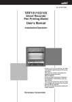
Graticules and Measurement Scales
Because the entire display is electronically generated, graticules are redrawn to correspond to the modes
selected by the user: waveform and/or vector or audio, composite or component, normal or magnifi-cation
modes. For example, the screen will not present waveform amplitude markings if only a vector is being
displayed. Below are descriptions of the graticules available when their respective modes are enabled.
COMPOSITE WAVEFORM GRATICULE
A composite waveform graticule consists of calibrated time markings for the X axis and calibrated amplitude markings for the Y axis. The horizontal reference
line at 0 IRE or units level is ten major divisions long in
100
normal mode (x1), and six divisions long in magnifica80
tion modes (x5, x10, x20). In a normal 1H mode (one
horizontal line displayed), each major horizontal division
60
is equal to 5µs. When two video lines are displayed
40
(2H mode) the horizontal scale then becomes 10µs per
20
division and finally in 3H mode each horizontal division
becomes 15µs. The time base of a major division is
0
indicated in the upper right corner of the display for
-20
horizontal sweeps. For vertical sweeps, the divisions
-40
are not calibrated, so no value is shown. For magnificaNTSC
VIDEOTEK
tion modes, this number will be scaled relative to a 1H
Figure 3
NTSC Waveform
sweep.
The NTSC graticule has a vertical scale in IRE units
for peak-to-peak amplitude measurements. The left side of the graticule scale is labeled [40 IRE to +100 IRE.
The conversion factor for IRE to voltage for a standard 1V p-p video signal is 1 IRE = 7.14mV. The scale is
drawn in 10 IRE vertical divisions, but labeled every 20 IRE. An additional dashed line at 7.5 IRE is available
for black level reference setup. Refer to Figure 2. The four corner brackets indicate the safe title area of the
video display.
16
The PAL graticule is labeled similar to the NTSC
graticule with units ranging from [40 to +100 units, plus
an additional [43 units line. The conversion factor for
units to volts is 1 unit = 6.99mV for a 1V p-p PAL signal.
The right side has a millivolt scale for easy conversion,
with [0.3 and +0.7 levels labeled. Refer to Figure 3.
+ .7
100
80
60
COMPONENT WAVEFORM GRATICULE
The horizontal scale for component waveform graticule is identical to that described for composite graticules. Vertical amplitude measurement is in millivolts,
with the scale drawn in 0.1 volt divisions. The labeled
divisions on the left are [0.3, 0, and +0.7 volts. An
additional dashed line indicating offset level is shown at
+0.35 volts, also labeled on the left. Refer to Figure 4.
40
20
0
-20
-40
-.3
VIDEOTEK
PAL
Figure 4
COMPOSITE AND COMPONENT VECTOR
GRATICULES
The vector graticules allow measurement of composite chroma phase and saturation relative to burst. It also
permits component signals to be displayed for amplitude
and timing checks.
For NTSC vector targets, the chrominance vector
places the color bar dots into a system of targets, as is
shown in Figure 5. A small target represents ± 2.5 IRE
chroma amplitude and ± 2.5E of chroma phase, and a
larger target is equivalent to ± 10E and ± 20% of chroma
level.
On the PAL vector graticule each chrominance vector
related to the +V burst terminates into a target with outer
and inner dimensions. The outer target dimensions are
all equal to ± 10E of chroma phase and ± 20% of
chroma level, and inner targets which are ± 3E and ±
5%. A vector dot related to the [V burst terminates into
a target with only inner dimensions shown as described
above. (See Figure 6).
PAL Waveform
+ .7
.35
0
- .3
VIDEOTEK
Figure 5
Component Waveform
R
R
Y
Y
PAL
Figure 7
Q
B
B
G
M
M
-I
G
C
C
NTSC
VIDEOTEK
Figure 6
PAL Vector
17
VIDEOTEK
NTSC Vector
The composite vector graticules also have markings
for coarse differential phase and gain measurements.
Degree ticks on the left side of the vector graticule circle
are spaced at 2E increments for differential phase
measurement. The horizontal radial line on the left side
of the circle has a mark indicating nominal burst amplitude. Amplitude lines near the edge of the circle
indicate 5%, 10%, and 15% differential gain. The
NTSC version has I and Q graticule lines, with tick
marks indicating nominal amplitude for each bar. The
PAL version has ± V radial lines with 75% and 100%
burst marks.
For an example of a component vector graticule, see
Figure 7. The markings follow the color bar boxes only;
there is no burst reference in component color.
R
M
Y
B
G
C
VIDEOTEK
Figure 8
Component Vector
AUDIO
Two horizontal scales, one for each stereo channel,
appearing in the bottom right portion of the display,
comprise the audio graticule. The letters "L" and "R"
designate left and right channel levels, and a number,
either "1" or "2", indicates which of the two audio input
pairs is currently selected. The large tick mark on each
scale indicates nominal signal amplitude for the selected audio level. Smaller marks on either side of the
larger one represent ± 1 dB levels. Refer to Figure 8.
COMBO GRATICULES
When several modes are selected at once, such as
L1
waveform/vector or waveform/audio, a combo graticule
R
is displayed, which is made up of the two graticules of
VIDEOTEK
the current display modes. The waveform/vector
Audio
combo graticule is drawn similarly to that of an etched Figure 9
CRT scope, with waveform amplitude lines omitted
within the vector graticule circle. (See Figure 9, Figure 10, and Figure 11). For the waveform/audio combo
graticule, waveform amplitude lines are eliminated from the lower right portion of the display as shown in
Figure 12, Figure 13 and Figure 14. Deselecting a display type when a combo mode is currently displayed
will cause the graticule to be redrawn.
100
+ .7
100
R
M
80
60
Y
R
80
60
Q
40
M
Y
40
B
20
B
20
-I
0
0
G
-20
G
-20
C
-40
-40
NTSC
Figure 10
VIDEOTEK
PAL
NTSC Waveform/Vector Combo
Figure 11
18
C
-.3
VIDEOTEK
PAL Waveform/Vector Combo
+ .7
100
R
M
80
60
Y
.35
40
B
20
0
0
G
-20
C
L
R
-40
- .3
NTSC
VIDEOTEK
Figure 12
Component
Waveform/Vector Combo
Figure 13
+ .7
100
VIDEOTEK
NTSC Waveform/Audio Combo
+ .7
80
60
.35
40
20
0
0
-20
L
R
-40
PAL
Figure 14
- .3
L
R
VIDEOTEK
VIDEOTEK
Figure 15
PAL Waveform/Audio Combo
Component
Waveform/Audio Combo
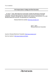
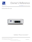
Operating the VTM-100 From a PC
Communication between the VTM-100 and a computer requires an RS-232 serial link configured as 1200
baud, no parity, 8 data bits and one stop bit. A null modem adaptor is required to connect the computer's
RS-232 port with the RS-232 port on the VTM-100. The chassis connector on the VTM-100 back panel is a
DB-9M. (See Figure 15). The computer must be running a terminal emulation program, such as the
commercially available ProComm, which the operator uses as the interface to enter and transmit commands
to the VTM-100.
Upon power up, or after selecting via Computer in the Setup/Control menu, the VTM-100 will display on
the computer a welcome message, and the prompt "VTM100>". At this prompt the operator can type a
command, or HELP to get a list of available commands. All characters are converted to uppercase, meaning
the operator input is case insensitive; any combination of upper and lowercase characters is acceptable. The
backspace key (ASCII character 8) erases the last character. Parameters are separated by one or more
spaces or tabs.
When entering a command, the operator need only type as many characters as is necessary to distinguish
it from another command. For example, "RE" is ambiguous because both "RECALL" and "REF" start with it,
but "REC" will be recognized as "RECALL". In the summary to follow, the minimum abbreviation for a
command to be recognized is indicated by the required letters being shown in upper case.
The summary that follows lists each command followed by parameters enclosed in brackets [ ], with individual parameter choices separated by "|". The brackets should not be used when entering the parameters.
The brackets indicate that including those parameters is optional when entering a command. Entering a
command with no parameters will return the current status of that selection, if appropriate. Otherwise, the
19
operator may choose to enter along with the command one of the parameters listed inside the brackets as
specified in the command description.
V TM -100
DB -9 MALE
PERSONAL COMPUTER
DB -9 MALE
2
232 Tx
3
3
232 Rx
2
5
232 GND
5
Figure 16
RS-232 Connection Diagram
Computer Command Summary
DISPLAY SELECTION COMMANDS
WFM
[ ON | OFF ]
Turn the waveform display on or off. Type WFM by itself to get the current waveform status.
VECtor
[ ON | OFF ]
Turn the vector display on or off. If vector is turned on, audio display is automatically turned off.
Type VECTOR by itself to get the current vector status.
Audio
[ 1 | 2 | OFF ]
Turns on the audio display and displays audio input 1 or 2, or turns audio off. If audio is turned
on, vector display is automatically turned off. Type AUDIO by itself to get the current audio status.
MEMORY COMMANDS
STore
[ 1 | 2 | 3 | 4 | 5 ] { name }
Store the current system settings in one of five memory locations, and optionally give the memory
a name. The default name is "MEMORY". If a memory is already stored in the selected location,
it is overwritten. A name can be up to 8 characters in length.
RECall
[ 1 | 2 | 3 | 4 | 5 | memname ]
Retrieve the system settings stored in the given memory location number, or the first location with
the name "memname". Type RECALL by itself to list the names of all currently stored memories.
Erase
[ 1 | 2 | 3 | 4 | 5 | memname ]
Erase the memory stored under the given memory location number, or the first location with the
name "memname".
20
POSITION COMMANDS
VHpos
[ 0 | offset | -offset ]
Change the vector horizontal position from its current location by the specified integer offset. An
offset of 0 will center the vector horizontally. A positive offset will move the vector right, and a
negative offset will move the vector left. Type VHPOS by itself to get the current vector horizontal
position. The vector horizontal position range is approximately [80 to +160.
VVpos
[ 0 | offset | -offset ]
Change the vector vertical position from its current location by the specified integer offset. An
offset of 0 will center the vector vertically. A positive offset will move the vector up, and a negative
offset will move the vector down. Type VVPOS by itself to get the current vector vertical position.
The vector vertical position range is approximately [180 to +60.
WHpos
[ 0 | offset | -offset ]
Change the waveform horizontal position from its current location by the specified integer offset.
An offset of 0 will center the waveform horizontally. A positive offset will move the waveform right,
and a negative offset will move the waveform left. Type WHPOS by itself to get the current
waveform horizontal position. The waveform horizontal position range varies with the display
mode. The overall range is plus or minus approximately 430 times the number of inputs in
horizontal sweeps, 520 times the number of inputs in 60 Hz vertical sweep, and 620 times the
number of inputs in 50 Hz vertical sweep.
WVpos
[ 0 | offset | -offset ]
Change the waveform vertical position from its current location by the specified integer offset. An
offset of 0 will center the waveform vertically. A positive offset will move the waveform up, and a
negative offset will move the waveform down. Type WVPOS by itself to get the current waveform
vertical position. The waveform vertical position range is approximately [120 to +120.
PHase
[ [360 ... +360 ]
Rotate the vector by the specified integer offset in degrees. A positive offset will rotate the vector
clockwise, and a negative offset will rotate it counterclockwise.
INPUT SETTING COMMANDS
Input [ input { filter } { input { filter } { input { filter } } } ]
Set up the inputs and filters. Up to three inputs and filters can be entered. In composite mode,
a filter can be specified after each input, or the input will default to flat filter. In component mode,
no filters can be entered. Type INPUT without any parameters to get the current input status.
Valid input parameters are for composite { A | B | C }, for component GBR { G | B | R }, for
component color difference { Y | B-Y | R-Y }. Optional filter parameters, which are only valid for
composite formats, are { FL | LP | CH }, representing flat, low pass, and chroma filters respectively.
REF
[ INT | EXT ]
Set the reference to internal (the first input selected in composite format, or the G/Y input in the
component formats), or external. Type REF by itself to get the current reference.
DISPLAY SETTING COMMANDS
PArade
In waveform mode, multiple inputs will be displayed side by side.
Overlay
In waveform mode, multiple inputs will be displayed on top of each other.
21
Gain
[ 50 ... 500 ]
Set the waveform and vector gain from 50% to 500% of full scale. Type GAIN by itself to get the
current gain.
Mag
[ 1 | 5 | 10 | 20 ]
Set the waveform time magnification to x1, x5, x10, or x20. Type MAG by itself to get the current
magnification.
SWeep
[H|V]
Set the waveform sweep to Horizontal (line rate) or Vertical (field rate). Type SWEEP by itself to
get the current sweep rate.
Bowtie
[ ON | OFF ]
In component video, set bowtie mode on or off. Type BOWTIE by itself to get the current bowtie
status.
Format
[ NTSC | PAL75 | PAL100 | GBR | BETA75 | BETA100 | MII75 | MII100 | SMPTE75 | SMPTE100
| EBU75 | EBU100 ]
Change the video format to one of the above formats. NTSC, SMPTE75, and SMPTE100 are
available only if the input video is at 60Hz, and PAL75, PAL100, EBU75, and EBU100 are available only at 50Hz. Type FORMAT by itself to get the current video format.
MISCELLANEOUS COMMANDS
Help
Display a list of commands.
?
Display a list of commands.
VERsion
Display the system software version number.
22
TROUBLESHOOTING
Verify that all cables are connected properly.
Verify that power is applied, and that cooling fan operates and front panel LED is lit.
SYMPTOM
POSSIBLE CAUSE
Video output from VTM-100 not visible on picture
monitor.
! Cable between VTM-100 output and video picture
Video picture monitor unable to lock to VTM-100
output.
! Monitor is not compatible with the video standard
Autodetection not working.
! Desired input to autodetect is not the current reference.
! Externally referenced with no input present.
! Reference video is not stable.
Stable VTM-100 display but no graticule or signal
visible.
! No display modes (waveform/vector/audio) currently
monitor not connected properly.
autodetected by the VTM-100 (NTSC/60Hz or PAL/50Hz).
! Reference video is not stable.
selected.
! Signal display and graticule colors the same as
background color.
Stable graticule but no signal display visible.
! Intensity turned all the way down.
! Signal display color same as background color.
! Waveform/vector position off screen.
Waveform/vector displays not locked.
! Externally referenced with no input.
! Displayed input not synchronous with reference.
Waveform/vector amplitudes too large.
! Video input not terminated.
! Variable gain not set to 100%.
Signal display creating smear on screen.
! Persistence set too high or at infinite.
Incorrect format graticule displayed.
! Wrong video format selected from on-screen menus.
Invalid vector display.
! Wrong video format selected from on-screen menus.
Graticule present but no audio signal level visible.
! Audio input not connected properly.
! Wrong audio channel selected.
Too much or too little audio signal.
! Input sensitivity and signal source level not matched.
Picture mix ratio incorrect.
! Wrong mix ratio selected from on-screen menus.
! Externally referenced with no input. (Background picture
mix is the reference video when Ext Ref is ON.)
Alarms not available.
! More than one input or filter selected.
! Current video format is component.
! Alarms only available in 1H or 1V composite displays.
! Alarms not available in line select mode.
Mouse not responsive.
! Mouse incorrectly connected to RS-232 port.
! Wrong mouse type selected from on-screen menus.
Remote PC unable to communicate with VTM-100.
! Null modem adapter not present between VTM-100 and
PC.
! RS-232 port on VTM-100 not set for via computer.
! Terminal emulation program on PC not configured for
1200 baud, no parity, 8 data bits, 1 stop bit.
Unable to display vector & audio combo
! Feature not available in VTM-100.
23
BLANK PAGE
24
Addendum
25