1
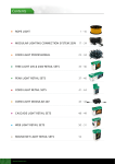
SERVICE
Software Revision 11
Option Programming
1/Vista and 2/Vista
Model Dispensers
IMPORTANT
SOFTWARE INFORMATION
This manual describes the operation of Software Revision 11 for 1/Vista and
2/Vista model dispensers. With exceptions noted below, this manual can be
used for Software Revisions 8 and 11.
Rev 8 only supports 1/Vista models. Example: 1/V390, 1/V590, etc.
Rev 11 supports both 1/Vista and 2/Vista models.
Rev 11 is required for 2/Vista models. Example: 2/V390, 2/V590, etc.
Option 04 must be set to 4 or 5 for 2/Vista models and 1, 2, or 3 for 1/Vista.
Option 24 and 28 settings vary between the 1/Vista and 2/Vista model series.
To determine the revision of Software residing on the computer, and if this is
the appropriate manual for describing that software, follow these steps:
1. Press the Position Select push-button.
2. Press and hold the Totals push-button until the ones digit is 0. Press and
hold the Totals push-button again until the tens digit is 0.
3. Press the Price Jog push-button twice to show the Software Revision
number, the two middle digits (between the decimals), in the money display*.
4. To use this manual, the Software Revision number –– again, the two digits
between the decimals –– should be “.08.” or higher, and the dispenser model
number must have a “1” or a “2” in the prefix and a “V” in the main body.
For example, 1/V387, 1/V390D, 2/V387, 2/V390, etc.
* The two far left digits shown in the money display are the Software Identification number, which is used to identify the type of software and not the revision.
See Option 02 description for more details.
Software Revision 11
Option Programming
1/Vista and 2/Vista
Model Dispensers
Service Manual
July 1999
Part No. 920205 Rev C
INDICATORS AND NOTATIONS
! DANGER
Danger indicates a hazard or unsafe practice which, if not avoided, will
result in severe injury or possibly death.
! WARNING
Warning indicates a hazard or unsafe practice which, if not avoided, may
result in severe injury or possibly death.
! CAUTION
Caution indicates a hazard or unsafe practice which, if not avoided, may
result in minor injury.
Note:
Important information to consider, otherwise, improper operation may
occur in some instances.
A vertical bar ( ) appearing on the right side of the pages
indicates text, figures, or tables that are new or changed
from the previous revision of this manual.
Part No. 920205 Rev C
July 1999
TABLE OF CONTENTS
Title
1.
2.
3.
Page
INTRODUCTION. . . . . . . . . . . . . . . . . . . . . . . . . . . . . . . . . . . . . . . . . . . . . . . . . . . . . . . . . . . . . . . . 1
1.1. Introduction to Option Programming . . . . . . . . . . . . . . . . . . . . . . . . . . . . . . . . . . . . . . . . . . 2
OPTION PROGRAMMING INSTRUCTIONS . . . . . . . . . . . . . . . . . . . . . . . . . . . . . . . . . . . . . . . . . 3
2.1. Option Categories . . . . . . . . . . . . . . . . . . . . . . . . . . . . . . . . . . . . . . . . . . . . . . . . . . . . . . . . . 3
2.2. Procedures for Option Programming. . . . . . . . . . . . . . . . . . . . . . . . . . . . . . . . . . . . . . . . . . . 3
2.2.1. Entering the Option Programming Mode . . . . . . . . . . . . . . . . . . . . . . . . . . . . . . . 4
2.2.2. Entering the Option Programming Mode via the Security Switch . . . . . . . . . . . . 5
OPTION PROGRAMMING DESCRIPTIONS . . . . . . . . . . . . . . . . . . . . . . . . . . . . . . . . . . . . . . . . . 7
01
Code History Display . . . . . . . . . . . . . . . . . . . . . . . . . . . . . . . . . . . . . . . . . . . . . . 7
02
Macro Setting . . . . . . . . . . . . . . . . . . . . . . . . . . . . . . . . . . . . . . . . . . . . . . . . . . . . 8
02
Macro Setting, continued . . . . . . . . . . . . . . . . . . . . . . . . . . . . . . . . . . . . . . . . . . . 9
03
Pump Configuration . . . . . . . . . . . . . . . . . . . . . . . . . . . . . . . . . . . . . . . . . . . . . . . 9
04
Gallons/Liters . . . . . . . . . . . . . . . . . . . . . . . . . . . . . . . . . . . . . . . . . . . . . . . . . . . 10
05
Nozzle Configuration . . . . . . . . . . . . . . . . . . . . . . . . . . . . . . . . . . . . . . . . . . . . . 10
06
Number Of Fueling Points . . . . . . . . . . . . . . . . . . . . . . . . . . . . . . . . . . . . . . . . . 11
07
Unit Prices Per Grade . . . . . . . . . . . . . . . . . . . . . . . . . . . . . . . . . . . . . . . . . . . . . 11
10
Totals Format . . . . . . . . . . . . . . . . . . . . . . . . . . . . . . . . . . . . . . . . . . . . . . . . . . . 12
11
Valve On Delay . . . . . . . . . . . . . . . . . . . . . . . . . . . . . . . . . . . . . . . . . . . . . . . . . 12
12
Time Out With No Pulses Received . . . . . . . . . . . . . . . . . . . . . . . . . . . . . . . . . . 12
13
Nozzle On Delay . . . . . . . . . . . . . . . . . . . . . . . . . . . . . . . . . . . . . . . . . . . . . . . . 13
14
Money Display Decimal Location . . . . . . . . . . . . . . . . . . . . . . . . . . . . . . . . . . . 13
15
Volume Display Decimal Location . . . . . . . . . . . . . . . . . . . . . . . . . . . . . . . . . . 14
16
Unit Price Display Decimal Location . . . . . . . . . . . . . . . . . . . . . . . . . . . . . . . . . 14
19
Number of Cash Digits . . . . . . . . . . . . . . . . . . . . . . . . . . . . . . . . . . . . . . . . . . . . 14
23
Flow Valve Sequence . . . . . . . . . . . . . . . . . . . . . . . . . . . . . . . . . . . . . . . . . . . . . 15
24
Unit Price Order . . . . . . . . . . . . . . . . . . . . . . . . . . . . . . . . . . . . . . . . . . . . . . . . . 15
25
Push-button Start/Stop . . . . . . . . . . . . . . . . . . . . . . . . . . . . . . . . . . . . . . . . . . . . 16
26
Totalizer Sequence Code Display . . . . . . . . . . . . . . . . . . . . . . . . . . . . . . . . . . . 17
28
Cash/Credit And Push-to-Start Switches . . . . . . . . . . . . . . . . . . . . . . . . . . . . . . 17
29
Flash Unit Price Displays In Idle State . . . . . . . . . . . . . . . . . . . . . . . . . . . . . . . 17
30
Blank Non-Selected Unit Price Displays . . . . . . . . . . . . . . . . . . . . . . . . . . . . . . 18
31
Beep After Nozzle Active . . . . . . . . . . . . . . . . . . . . . . . . . . . . . . . . . . . . . . . . . 18
34
Call On Push-to-Start . . . . . . . . . . . . . . . . . . . . . . . . . . . . . . . . . . . . . . . . . . . . . 18
36
Submersible Pump Relay Control . . . . . . . . . . . . . . . . . . . . . . . . . . . . . . . . . . . 19
37
Inhibit Vista Actuator Assembly LEDs . . . . . . . . . . . . . . . . . . . . . . . . . . . . . . . 19
38
Electromechanical Totalizer per Product or Meter . . . . . . . . . . . . . . . . . . . . . . 19
40
Money/Volume Default . . . . . . . . . . . . . . . . . . . . . . . . . . . . . . . . . . . . . . . . . . . 20
41
Money Only, Volume Only, Or Both . . . . . . . . . . . . . . . . . . . . . . . . . . . . . . . . . 20
42
Display Fill or Dashes On Fill Command . . . . . . . . . . . . . . . . . . . . . . . . . . . . . . 20
43
Preset Required . . . . . . . . . . . . . . . . . . . . . . . . . . . . . . . . . . . . . . . . . . . . . . . . . . 20
44
First Digit Entry Point For Money . . . . . . . . . . . . . . . . . . . . . . . . . . . . . . . . . . . 21
45
First Digit Entry Point For Volume . . . . . . . . . . . . . . . . . . . . . . . . . . . . . . . . . . 21
46
Volume Pre-Cutoff Amount . . . . . . . . . . . . . . . . . . . . . . . . . . . . . . . . . . . . . . . . 22
iii
July 1999
Part No. 920205 Rev C
TABLE OF CONTENTS, continued
Title
Page
3. OPTION PROGRAMMING DESCRIPTIONS, continued
51
Blend Ratios (Programming Sequence) . . . . . . . . . . . . . . . . . . . . . . . . . . . . . . .
52
Blend Error . . . . . . . . . . . . . . . . . . . . . . . . . . . . . . . . . . . . . . . . . . . . . . . . . . . . .
53
First Check Set . . . . . . . . . . . . . . . . . . . . . . . . . . . . . . . . . . . . . . . . . . . . . . . . . .
97
RAM Clear . . . . . . . . . . . . . . . . . . . . . . . . . . . . . . . . . . . . . . . . . . . . . . . . . . . . .
98
Code Allocation . . . . . . . . . . . . . . . . . . . . . . . . . . . . . . . . . . . . . . . . . . . . . . . . .
99
Exit Programming . . . . . . . . . . . . . . . . . . . . . . . . . . . . . . . . . . . . . . . . . . . . . . .
4. FAULT DETECTION AND REPORTING . . . . . . . . . . . . . . . . . . . . . . . . . . . . . . . . . . . . . . . . . . .
4.1. Introduction . . . . . . . . . . . . . . . . . . . . . . . . . . . . . . . . . . . . . . . . . . . . . . . . . . . . . . . . . . . . .
4.2. Clearing Faults. . . . . . . . . . . . . . . . . . . . . . . . . . . . . . . . . . . . . . . . . . . . . . . . . . . . . . . . . . .
4.3. Fault Code Status Descriptions . . . . . . . . . . . . . . . . . . . . . . . . . . . . . . . . . . . . . . . . . . . . . .
4.4. Fault Reporting . . . . . . . . . . . . . . . . . . . . . . . . . . . . . . . . . . . . . . . . . . . . . . . . . . . . . . . . . .
4.4.1. Totalizer Sequence Code Display . . . . . . . . . . . . . . . . . . . . . . . . . . . . . . . . . . . .
APPENDIX A. MACRO SETTINGS . . . . . . . . . . . . . . . . . . . . . . . . . . . . . . . . . . . . . . . . . . . . . . . . . . . .
22
24
24
25
26
27
29
29
29
29
31
32
35
A.1. Available Macros . . . . . . . . . . . . . . . . . . . . . . . . . . . . . . . . . . . . . . . . . . . . . . . . . . . 35
WARRANTY AND LIMITATION OF REMEDY AND LIABILITY. . . . . . . . . . . . . . Inside Back Cover
FCC WARNING . . . . . . . . . . . . . . . . . . . . . . . . . . . . . . . . . . . . . . . . . . . . . . . . . . . . . . . . . . . . .Back Cover
LIST OF FIGURES
Figure 4-1.
Figure 4-2.
Figure 4-3.
Fault Code Display . . . . . . . . . . . . . . . . . . . . . . . . . . . . . . . . . . . . . . . . . . . . . . . . 32
Main Sale Display Showing Transaction Counters . . . . . . . . . . . . . . . . . . . . . . . 33
Main Sale Display Showing Transaction Counter and Fault Code . . . . . . . . . . . 33
LIST OF TABLES
Table 3-1.
Table 4-1.
Table 4-2.
Table A-1.
Option 24 Data . . . . . . . . . . . . . . . . . . . . . . . . . . . . . . . . . . . . . . . . . . . . . . . . . . . 15
Fault Codes, Status, and Description . . . . . . . . . . . . . . . . . . . . . . . . . . . . . . . . . . 30
Fault Codes Status Effect on Dispenser . . . . . . . . . . . . . . . . . . . . . . . . . . . . . . . . 31
Rev 11 Option Settings by Dispenser Model Number . . . . . . . . . . . . . . . . . . . . 36
iv
Part No. 920205 Rev C
July 1999
1. INTRODUCTION
This manual describes the programming options of Duplex II computers that have software
revision 11. 2/Vista dispensers that require revision 11 or higher software can be identified by their
model number prefix of “2” and a main body designation of “V”. For example, 2/V387, 2/V390,
2/V590, 2/V595, etc. Also see “Important Software Information” on inside cover.
In this manual, model number prefix designations are shown but suffix designations are deleted,
except when the suffix is needed to distinguish one particular model variation from another. For
example, 2/V590D1 and 2/V590D1/U.
Any service problems which cannot be solved should be referred to Wayne Technical Support or
to the appropriate regional service office.
Wayne Technical Support
Austin, TX
1-800-926-3737
24 hours/7 days
Northeast Regional
Service Office
Salisbury, MD
410-546-6750
8:30AM-5:00PM Eastern
Southeast Regional
Service Office
Atlanta, GA
770-926-6005
8:30AM-5:00PM Eastern
North Central Regional
Service Office
Chicago, IL
773-693-7404
8:30AM-5:00PM Central
South Central Regional
Service Office
Houston, TX
281-871-5442
8:30AM-5:00PM Central
Southwest Regional
Service Office
Cypress, CA
714-952-1137
8:30AM-5:00PM Pacific
Northwest Regional
Service Office
San Ramon, CA
510-328-0400
8:30AM-5:00PM Pacific
Mid-Atlantic Regional
Service Office
Baltimore, MD
410-691-2200
8:30AM-5:00PM Eastern
1
July 1999
Part No. 920205 Rev C
1.1.
INTRODUCTION TO OPTION PROGRAMMING
The Duplex II computer can be programmed to control various Wayne dispenser models.
Computer option data settings provide a means for programming the computer to control a
specific dispenser model. The options are initially set at the factory. However, the procedures in this manual will enable you to change the data settings within the options, if necessary, to satisfy local conditions.
This manual does not cover dispenser interface with the Wayne® 2400 Management
Control System (2400 MCS) or Wayne Plus™ Retail Control System. Refer to the appropriate installation manual for the equipment that will be interfaced with the dispenser.
2
Part No. 920205 Rev C
July 1999
2. OPTION PROGRAMMING INSTRUCTIONS
This section provides option programming instructions to be used in conjunction with the option
descriptions in Section 3 and the option settings in Appendix A. Make sure that any changes to the
option settings are consistent with the available options for the particular dispenser model number.
2.1.
OPTION CATEGORIES
Options fall into four categories as follows:
2.2.
•
Specified options are those that are dictated by dispenser model number. Incorrect
dispenser operation may occur if a specified option is not set correctly. Options 02,
03, 05, 06, 07, 23, 24, 25, 28, and 51 are specified options.
•
Non-specified options are those that are not dictated by the dispenser model number
and may be altered to suit customer preference and local requirements. There are
default values for the non-specified options. These values are typical and should be
checked against local requirements.
•
Hidden options are those that cannot be viewed or altered from their default settings.
Many previous options are now hidden.
•
Service-only options are those that can be altered, only, if the security switch is set
when entering option programming. Service-only options consist of Options 02, 04,
51, and 97. These options can be viewed, but not changed, without setting the security switch.
PROCEDURES FOR OPTION PROGRAMMING
There are two procedures that can be used to enter the option programming mode to view
or change option settings.
The first procedure simply enters the option programming mode and can be used to change
any non-Hidden option except “Service-only” options.
The second procedure enters the option programming mode via a security switch, which
allows service personnel to change any non-Hidden option including “Service-only”
options.
Both procedures are discussed in detail on the following pages.
While performing either of these procedures, if the data setting for an option is changed
from the default setting, the display will flash when viewing that option and when viewing
Option 02, the macro setting. The altered option and Option 02 will stop flashing if the data
is changed back to the default setting. If the changes are saved, the displays will flash when
the option programming mode is entered on the next occasion. If 30 seconds pass without
making an entry, the computer will revert to normal mode without saving any changes.
3
July 1999
Part No. 920205 Rev C
2.2.
PROCEDURES FOR OPTION PROGRAMMING, continued
Refer to the Installation and Operation manual for the dispenser being serviced for the location of the push-buttons used in these procedures.
2.2.1.
Entering The Option Programming Mode
To enter the option programming mode to view or make changes, as allowed in
this mode, perform the following procedure:
1. Press the Position Select push-button.
2. Press and hold the Totals push-button until the ones digit in the unit price
display is 0. Press and hold the Totals push-button again until the tens digit
is 0. The fueling point number is now set to “00”, the money display on both
sides will show dashes and both sides of the dispenser will be inoperative.
3. Press the Price Jog push-button. The unit price display will show “OP01”
to indicate that you have entered the option programming mode and Option
01 has been selected.
4. Press Price Jog push-button to go to the desired programming option. As
the Price Jog push-button is pressed the unit price display(s) will show the
selected option in the range of “OP01” to “OP99”.
5. Press the Totals push-button to change the data in the selected option, or
Press the Price Jog push-button to go to the next desired programming
option.
6. Press the Price Jog push-button until Option 99 is displayed and Press the
Totals push-button to select the appropriate data; 03 to Exit and save
changes, 02 to Exit and do not save changes, or 01 to review the options
again.
7. Press the Price Jog push-button to display the original fueling point
number.
8. Press the Position Select push-button to return the dispenser to the normal
operating mode.
4
Part No. 920205 Rev C
July 1999
2.2.2.
Entering The Option Programming Mode Via The Security Switch
! WARNING
Electric Shock Hazard!
The procedure below requires that electrical power to the dispenser be turned ON.
Avoid touching any of the components on the circuit boards. Failure to do so may
result in serious injury.
In order to change Options 02, 04, 51, and 97 the security switch must be set.
To set the security switch and enter the option programming mode, locate the
Duplex II computer board and perform the following procedure:
1. Remove power from the board by removing connector J3.
2. Locate connector J6 and bridge (jumper) pins 3 & 5. Use jumper part
number 129930. Pin 1 of J6 is located closest to the center of the board.
3. Apply power to the board by re-installing connector J3. The unit price
display will show “OP01” to indicate that the security switch has been set,
you have entered the option programming mode, and Option 01 has been
selected.
4. Press the Price Jog push-button to go to the desired programming option.
As the Price Jog push-button is pressed the unit price display(s) will show
the selected option in the range of “OP01” to “OP99”.
5. Press the Totals push-button to change the data in the selected option.
6. Press the Price Jog push-button until Option 99 is displayed and Press the
Totals push-button to select the appropriate data of 03 to Exit and save
changes, 02 to Exit and do not save changes, or 01 to review the options
again.
7. Remove the jumper from connector J6.
If the jumper is not removed, exiting programming through Option 99 is
inhibited and a cycle back to Option 01 will occur when performing the
next step.
8. Press the Price Jog push-button to display the original fueling point
number.
9. Press the Position Select push-button to return the dispenser to the normal
operating mode.
5
July 1999
Part No. 920205 Rev C
6
Part No. 920205 Rev C
July 1999
3. OPTION PROGRAMMING DESCRIPTIONS
This section describes the programming options available in Duplex II computers that have software revision 11.
OPTION
DESCRIPTION
01
Code History Display
Read Only — This option cannot be changed.
This option displays the last Fault Code (Error,
Hydraulic, or Service) information.
The format for the display of a fault code is:
Sale Money = NNNNN.S
Sale Volume = PF-CC.T
Unit Price = OP01
NNNNN - Transaction counter, increments from 00000 to 59999.
It is incremented with each sale and allocated to each
fault code detected.
S
- Side, 1 or 2, that the fault code was detected on is the
junction box side.
P
- Product that was selected at the time the fault occurred.
The range is 0 - 7 with 0 meaning that no position was
selected.
F
- Identifies the fault source if the fault can be linked to a
hydraulic condition. The range is 0 - 7, “H”, or “L.” The
numeric values indicate positions (0 = none) while “H” and
“L” indicate blending feed stocks.
CC
- Fault Code number in the range of 00 - 99.
T
- Fault Code Status:
1 = Error 2 = Hydraulic 3 = Service.
Pressing the Totals button displays fault codes, detected from both sides,
beginning with the most recent. The last 16 are stored and displayed.
Pressing the Price Jog button at any point increments to the next option.
See Section 4 for more details on fault codes, their status and definitions. See Fault Codes 20 and 21 in Section 4 for display format.
7
July 1999
Part No. 920205 Rev C
3. OPTION PROGRAMMING DESCRIPTIONS, continued
OPTION
DESCRIPTION
02
Macro Setting
This is a read only option, unless option programming is entered via the
security switch as discussed in Section 2.2.2.
DATA
00 - Manufacturing default.
02 to 13 Macro numbers.
See Appendix A for available options in each macro. Remember, this
manual only applies to 1/Vista and 2/Vista model dispensers which are
the Enhanced Vista models. See separate manual for Standard Vista.
The display format in this option is:
Sale Money = FF.RR.SS
Salh e Volume= TT
DD
Unit Price = OP02
FF - Software ID number 00 - 99. Identifies the use type of software
residing in the dispenser.
11 = Domestic use, 12 = International(Export) use,
13 = ISM use, 14 = Domestic Touchscreen use
RR - Software revision number 00 - 99. For example Rev 08 or Rev 11
SS - Revision sub number 00 - 99,
00 = production release.
TT - Datalink pump type 00 - 99.
DD - Option data 00, 02 to 13. This is the Macro number.
OP02 - Option 02
Note the following about this option and macros:
1. Macros set all option data defined in the macro table (see Appendix
A) and hide those options that may not be configured to a setting
different from the macro table configuration.
2. Settings which are hidden are not displayed in the option setting
sequence.
3. If a data setting is altered from the macro setting, the display will flash
(for both the altered option(s) and Option 02). The display will flash
when reviewing the options prior to, or after, saving the option data.
8
Part No. 920205 Rev C
July 1999
3. OPTION PROGRAMMING DESCRIPTIONS, continued
OPTION
DESCRIPTION
02
Macro Setting, continued
03
4.
If Option 02 is entered and is flashing (data changed),
changing the macro will reset any altered options to that
macro’s default.
5.
Once a macro other than Macro 00 is saved, Macro 00 will be
locked out.
6.
If a RAM clear is performed, the macro setting will default to
Macro 00 and be ready for option programming to one of the
other Macros.
Pump Configuration
Configures the computer for the type of dispenser it will be controlling and the type of communications it will use with the control
system. Data marked “SC-82 communications” will operate with
any Rev. of data link control system CPU. All other data requires
control system CPU Rev. 49 or higher.
DATA
01
SC-82 Emulation
(SC-82 communications)
02
Non-Blender
(Duplex communications)
03
Fixed Blender
(Duplex communications)
04
Reserved
(Do not use.)
05
Variable Blender
(Duplex communications)
06
Reserved
(Do not use.)
07
Duo-2
(Duplex communications)
08
UniHose MGD
(Duplex communications)
9
July 1999
Part No. 920205 Rev C
3. OPTION PROGRAMMING DESCRIPTIONS, continued
OPTION
DESCRIPTION
04
Gallons/Liters
This is a read only option, unless option programming is entered via
the security switch as discussed in Section 2.2.2.
This option is interlocked to Option 53. The data setting in this
option determines the data range allowed in Option 53.
DATA
01
02
03
04
05
Gallons - Volume based on 1072 pulses per gallon.
Liters - Volume based on 1072 pulses per liter.
Liters - Volume based on 283 pulses per liter.
Gallons - Volume based on 1514 pulses per gallon.*
Liters - Volume based on 400 pulses per liter.*
* Required setting for 2/Vista models, U.S. gal. or liter.
05
Nozzle Configuration
Sets the number and location of nozzle positions active on the dispenser.
DATA
01
Nozzle A
02
Nozzle A
Nozzle B
03
Nozzle A
Nozzle B
Nozzle C
04
Nozzle A
Nozzle B
Nozzle C
Nozzle D
05
Nozzle B
06
Nozzle B
Nozzle C
07
Nozzle B
Nozzle C
Nozzle D
10
Part No. 920205 Rev C
July 1999
3. OPTION PROGRAMMING DESCRIPTIONS, continued
OPTION
DESCRIPTION
06
Number Of Fueling Points
Sets the Duplex II computer to control either one or two fueling
points on the dispenser.
DATA
07
01
One Fueling Point per computer.
02
Two Fueling Points per computer.
Unit Prices Per Grade
Sets the Duplex II computer to assign either, one unit price per grade
(non-cash/credit) or two unit prices per grade (cash/credit) (C/C).
With either of the data selections below, the Duplex II computer
automatically determines if cash/credit selection and cash/credit
confirmation are required.
DATA
01
One unit price per grade (Non-Cash/Credit).
C/C Confirmation is not required at dispenser and
C/C Selection is not required to begin sale.
02
Two unit prices per grade (Cash/Credit).
C/C Confirmation is required at dispenser and
C/C Selection is required to begin sale.
11
July 1999
Part No. 920205 Rev C
3. OPTION PROGRAMMING DESCRIPTIONS, continued
OPTION
DESCRIPTION
10
Totals Format
Sets the computer to store money totals in one of three formats.
First, to separate cash and credit totals per position. Second, to
combine all money per position regardless if it’s cash or credit.
Third, to calculate all money per fueling point.
If Option 10 is set to separate cash and credit totals then Option 07
must be set for two unit prices per grade.
DATA
01
02
03
11
Money totals are separated into cash totals and credit
totals per position.
Money totals are calculated equal to cash plus credit per
position.
Money totals are calculated per fueling point only.
Valve On Delay
Programs a delay between the time that the relay select line is energized and the slow valve is turned on. This delay is intended to give
the leak detectors time to perform their check.
DATA
2 to 6 seconds in 0.5 second increments.
12
Time Out With No Pulses Received
If, after the dispenser starts its reset, pulses to begin a sale, or
during a sale, are not received for the programmed time period, the
dispenser goes out of use and Fault Code 08 is set.
DATA
120 to 300 seconds in 10 second increments.
Cannot be disabled.
12
Part No. 920205 Rev C
July 1999
3. OPTION PROGRAMMING DESCRIPTIONS, continued
OPTION
DESCRIPTION
13
Nozzle On Delay
When enabled, sets a 3 - 4 second time which the nozzle switch
must be turned off before moving the switch to the on position will
be recognized. This prevents a customer from inadvertently resetting the sale amount. For example:
1.
The nozzle is turned off and the dispenser goes out of use.
The computer initializes a 3 - 4 second delay of nozzle-on
recognition.
2.
If the nozzle comes back on in less than 3 - 4 seconds the
computer ignores the switch closure and does not reset.
3.
If the nozzle comes on after the 3 - 4 second timer has
expired, the computer resets and starts the sale.
DATA
01
02
14
Disabled.
Enabled.
Money Display Decimal Location
Sets the location of the money display decimal point. This same
location is used on the preset assembly if present.
DATA
01
02
03
04
05
.X
. XX
. XXX
. XXXX
No Decimal Point
13
July 1999
Part No. 920205 Rev C
3. OPTION PROGRAMMING DESCRIPTIONS, continued
OPTION
DESCRIPTION
15
Volume Display Decimal Location
Sets the location of the volume display decimal point. This same
location is used on the preset assembly if present.
DATA
16
01
. XX
02
. XXX
Unit Price Display Decimal Location
Sets the location of the unit price decimal point.
DATA
19
01
.X
02
. XX
03
. XXX
04
No decimal point.
Number of Cash Digits
Sets the number of digits which will be shown in the money display.
DATA
01
5 digits
02
6 digits
14
Part No. 920205 Rev C
July 1999
3. OPTION PROGRAMMING DESCRIPTIONS, continued
OPTION
DESCRIPTION
23
Flow Valve Sequence
Sets the sequence which the computer turns the flow control valves
on and off. In dispensers with new style hydraulics (with a two
stage actuator), this option must always be set at 02. In dispensers
with old style hydraulics (two external electric solenoid valves),
this option must be set to 01.
DATA
24
01
S-F-S:
Slow on, Fast off;
Fast on, slow off;
Slow on, Fast off.
02
S-SF-S
Slow on, Fast off;
Slow on, Fast on;
Slow on, Fast off.
Unit Price Order
Reverses the order of unit price positions, switch inputs, and lighted
cash credit button outputs on each side of the dispenser. See Table
3-1 for data.
DATA
TABLE 3-1. OPTION 24 DATA
Option 24 Data
Side 1 Unit Price
Position Order
Side 2 Unit Price
Position Order
01
Left to Right
Left to Right
02
Left to Right
Right to Left
03
Right to Left
Left to Right
04
Right to Left
Right to Left
Note: Side 1 of the dispenser is the junction box side.
15
July 1999
Part No. 920205 Rev C
3. OPTION PROGRAMMING DESCRIPTIONS, continued
OPTION
DESCRIPTION
25
Push-button Start/Stop
Enables or disables the push-to-start option.
If the option is enabled, a push-to-start switch must be pressed
before the dispenser will reset. If the option is disabled the
dispenser will reset without a push-to-start signal.
Note: NFPA 30A requires the dispenser to be “manually activated.” This requires a separate intentional operation other than simply removing the nozzle from its hang up
position.
DATA
01
Disabled.
For use with Lift-to-Start models.
02
Enabled Push-to-start Switch.
A push-to-start switch is the only valid push-to-start
signal. The push-to-start switch is a normally open switch
which ultimately connects to pins 7 and 5 of the J6
connector on the lighted cash credit interface board. If this
switch is continuously closed for 30 seconds Fault Code
01 is set.
03
Enabled Push-to-start, Cash/Credit, or Grade Select
Switches.
The select switches are considered valid push-to-start
signals. These are normally open switches which ultimately connect to the J5 connector on the lighted cash
credit interface board.
04
Reserved. (Do not use.)
16
Part No. 920205 Rev C
July 1999
3. OPTION PROGRAMMING DESCRIPTIONS, continued
OPTION
DESCRIPTION
26
Totalizer Sequence Code Display
Sets the computer to display the most recent fault code detected, for
a given side of a dispenser, before any totals have been displayed.
DATA
01
02
28
Enable.
Disable.
Display fault code.
Do not display fault code.
Cash/Credit And Push-to-Start Switches
Sets the computer to control the proper number of lighted or
unlighted cash/credit or Push-to-Start switches.
DATA
29
01
One cash switch and one credit switch or one Push-toStart bar per side.
02
One set of cash/credit switches or one Push-to-Start bar
per nozzle, or lighted cash and credit switches.
03
Cash/credit selection or Push-to-Start required from
dispenser mounted card activated terminal.
Flash Unit Price Displays In Idle State
Sets the computer to either flash or not flash the unit price displays.
DATA
01
Do not flash unit price displays.
02
Flash unit price displays when the dispenser is idle
and all nozzle switches are off.
03
Flash unit price displays after a nozzle switch is
turned on and until product flow begins.
17
July 1999
Part No. 920205 Rev C
3. OPTION PROGRAMMING DESCRIPTIONS, continued
OPTION
DESCRIPTION
30
Blank Non-Selected Unit Price Displays
Sets the computer to display dashes in the non-selected unit price
displays, or to blank out the non-selected unit price displays, when
a nozzle switch is turned on.
DATA
31
01
Display dashes in non-selected unit price displays.
02
Blank out non-selected unit price displays.
Beep After Nozzle Active
DATA
01
Beep until authorized
Beep during reset cycle
No.
Yes.
02
Beep until authorized
Beep during reset cycle
Yes.
Yes.
03
Beep until authorized
Beep during reset cycle
No.
No.
04
Beep until authorized
Beep during reset cycle
Yes.
No.
Note: Push-to-Start dispensers will beep on nozzle active until Push-to-Start requirements
are met regardless of how Option 31 is set.
34
Call On Push-to-Start
Tells the computer when to generate a call signal to the control
system.
DATA
01
Call on product selection.
02
Call after product selection and
Push-to-Start is satisfied.
18
Part No. 920205 Rev C
July 1999
3. OPTION PROGRAMMING DESCRIPTIONS, continued
OPTION
DESCRIPTION
36
Submersible Pump Relay Control
DATA
01
Relay turns ON if nozzle is out and Authorized.
02
Relay turns ON if nozzle is out and not Authorized.
Note: If there is no authorization in 60 seconds, the relay is turned OFF.
37
Inhibit Vista Actuator Assembly LEDs
DATA
01
Do not inhibit LEDs.
LEDs will flash when a nozzle is out
and user action is required.
02
Inhibit LEDs.
LEDs will not flash if all of the
following are true:
The dispenser is not in stand alone.
The dispenser is not authorized from the controller.
Option 25 is set at 03.
Option 03 is not set at 04, 05, or 08.
A nozzle is out.
38
Electromechanical Totalizer per Product or Meter
DATA
01
One EMT per product.
02
One EMT per meter.
19
July 1999
Part No. 920205 Rev C
3. OPTION PROGRAMMING DESCRIPTIONS, continued
OPTION
DESCRIPTION
40
Money/Volume Default
Tells the preset assembly which mode, money or volume, to default to at power
up or after a completed sale.
DATA
41
01
Default to the money mode.
02
Default to the volume mode.
03
No default.
Money Only, Volume Only, Or Both
Tells the preset controller whether it can operate in only the money mode, only
the volume mode, or if it can be toggled between the two.
DATA
42
01
Money or volume sales can be preset.
02
Money sales can be preset (money mode).
03
Volume sales can be preset (volume mode).
Display Fill Or Dashes On Fill Command
Tells the preset controller to display dashes or the word “FILL” when a customer
selects fill.
DATA
43
01
“FILL” is displayed.
02
“- - - -” is displayed.
Preset Required
Tells the preset controller if a preset selection is required prior to beginning a
sale.
DATA
01
Preset entry not required before a sale begins.
02
Preset entry required before a sale begins.
20
Part No. 920205 Rev C
July 1999
3. OPTION PROGRAMMING DESCRIPTIONS, continued
OPTION
DESCRIPTION
44
First Digit Entry Point For Money
Sets the position at which the money digit(s) entered will be displayed.
The X below indicates the position on the display where the last digit
entered will be shown. All digits to the right of the X position will remain
zero.
DATA
01
02
03
04
05
06
X000.00
- X00.00
- - X0.00
- - - X.00
- - - - .X0
- - - - .- X
Note: The decimal point location in the above Data assumes that two decimal places were selected
in Option 14; therefore, if Option 44 is set to Data 04, and a 2 and 3 are entered at the keypad,
“23.00” will be displayed. If Option 44 is set to Data 05, the same entry would display “2.30”.
45
First Digit Entry Point For Volume
Sets the position at which the volume digit(s) entered will be displayed.
The X below indicates the position on the display where the last digit
entered will be shown. All digits to the right of the X position will remain
zero.
DATA
01
02
03
04
05
06
X00.000
- X0.000
- - X.000
- - - .X00
- - - .- X0
- - - .- - X
Note: The decimal point location in the above Data assumes that three decimal places were selected
in Option 15; therefore, if Option 45 is set to Data 03, and a 2 and 3 are entered at the keypad,
“23.000” will be displayed. If Option 45 is set to Data 04, the same entry would display
“2.300”.
21
July 1999
Part No. 920205 Rev C
3. OPTION PROGRAMMING DESCRIPTIONS, continued
OPTION
DESCRIPTION
46
Volume Pre-Cutoff Amount
Sets the volume amount before the end of a preset sale at which the
dispenser will go into slow flow. For example, if the pre-cutoff
amount is set at .15, the dispenser will slow down .15 volume units
before the end of a preset sale.
Note: The DATA range below allows the flexibility to change this setting from the Default
setting of .15 gallons (.57 liters). Various settings can be entered until a suitable slow
down interval is obtained. The value entered should provide NO LESS than a 5 to 6
second slow down time, otherwise, Preset Overruns may occur.
DATA
.01 to 2.55 volume units (Gallons or Liters) in
one one-hundredth of a volume unit increments.
51
Blend Ratios (Programming Sequence)
Note: This option can only be altered from its default value if the security switch is set when
entering option programming as discussed in Section 2.2.2.
Note: If the dispenser is connected to a control system, the blend ratios must be entered in
this option first and then at the control system. If the control system does not agree
with the dispenser, data link communications will cease and the dispenser will drop
off line. The control system will not override the blend ratios entered in the
dispenser.(Weights and Measures requirement.)
This option (applicable to blending dispensers only) sets the blend
ratios which are used to mix the end grades when dispensing the
blended grades of product. The entries are made as a percentage of
high product; for example, an entry of 75 would produce a blend
made up of 75 percent high product and 25 percent low product.
The blends are assigned by hose position. A variable blender can
have ratios set in positions 2 through 7. The representative unit
price displays for positions 2 through 7 are either right to left or
bottom to top respectively, depending on the type of display
installed in the dispenser. A fixed blender can have a blend ratio set
in position 3 only. This ratio must be between 01 and 99 with
positions 2 and 4 fixed at 000 and 100 respectively.
22
Part No. 920205 Rev C
July 1999
3. OPTION PROGRAMMING DESCRIPTIONS, continued
OPTION
DESCRIPTION
51
Blend Ratios (Programming Sequence), continued
Once the correct programming is determined the steps to enter that
programming (after setting the security switch) are as follows:
1.
Upon entering Option 51 the money display shows a
sequence number and the volume display is dashes. The
sequence number is a count of how many times the blend
ratio data has been changed and saved. Press the Totals
push-button to display the first blend position in the money
display, and the currently programmed data (blend ratio)
for that position in the volume display.
2.
Press the Totals push-button to change the blend ratio.
The ratio can be set in 1% increments. Each digit is set
individually by releasing and pushing the Totals button to
advance to the next digit. Dashes are not valid digits for
blend ratios.
3.
Press the Price Jog push-button to increment to the next
blend position.
4.
Repeat Steps 2 and 3 until all blend ratios have been
entered.
Note: The blend ratios can also be viewed, without entering option programming, by
pressing the Totals button and then the Price Jog button to enter the Audit Report
Display Mode. In this mode, the blend ratios are shown in the unit price displays. The
sale volume shows the number of times a RAM clear has been performed and the sale
money shows the combined total of, the number of RAM clears + the number of times
Option 04 (Gal/Lit) has been changed + the number of times Option 51 has been
changed. Non-blending dispenser unit price displays will show “Ar” in the Audit
Report mode. Press the Totals button to exit this mode.
23
July 1999
Part No. 920205 Rev C
3. OPTION PROGRAMMING DESCRIPTIONS, continued
OPTION
DESCRIPTION
52
Blend Error
Sets the percentage by which the programmed blend ratio may fluctuate before a blend error is recorded. For example, if option 52 is
set to 2 the selected blend ratio may fluctuate ± 2%; if the ratio fluctuates more than ± 2% the dispenser is shut down and a blend error
is displayed at the next reset. Option applies to blending dispensers
only.
DATA
1% to 5% in 1% increments.
53
First Check Set
Sets the volume amount at which the computer begins to check the
blend ratio for correctness. For example, if Option 53 is set at 1.2,
the first 1.2 volume units would be dispensed before the blend ratio
was checked. Once the 1.2 volume units is exceeded, the blend
ratio will continue to be checked throughout the rest of the sale.
Option applies to blending dispensers only.
Option 53 is interlocked to Option 04 (Gallon/Liter).
DATA
0.2 to 5.0 Gallons, in 0.2 increments, when
Option 04 = 1 (Gallons).
0.8 to 20.0 Liters, in 0.2 increments, when
Option 04 = 2 (Liters) or 3 (Liters).
24
Part No. 920205 Rev C
July 1999
3. OPTION PROGRAMMING DESCRIPTIONS, continued
OPTION
DESCRIPTION
97
RAM Clear
Provides a means for clearing the RAM on the computer. The
RAM clear counter is shown in the sale volume display during the
Audit Report Display Mode as discussed on page 23. To perform a
RAM clear follow these steps:
1.
Enter option programming via the security switch as
discussed in Section 2.2.2 and leave the security jumper
installed.
2.
Press the Price Jog push-button to go to Option 97 where
the sale money display will show XAB; AB being the right
hand two digits.
3.
Use the Totals push-button to change the value in the
volume display to XBA. For example, if the money
display shows 06 in the right hand two digits, enter 60 in
the right hand two digits in the volume display.
4.
Press the Price Jog push-button; a RAM clear will occur
in a few seconds and the computer will immediately enter
Option 01.
5.
Use the Price Jog and Totals push-buttons to reset the
options as necessary and Save the new settings with
Option 99 set to 03.
6.
Remove the security jumper.
7.
Press the Price Jog and then the Position Select pushbutton to return the dispenser to the normal operating
mode.
Note: Reset the fueling point number and unit prices as necessary after performing this
procedure.
25
July 1999
Part No. 920205 Rev C
3. OPTION PROGRAMMING DESCRIPTIONS, continued
OPTION
DESCRIPTION
98
Code Allocation
Allows the status of some fault codes to be changed as discussed in
Section 4. This option will display only the changeable fault code
statuses as follows:
1.
When Option 98 is entered the money and volume
displays will show dashes.
2.
Press the Totals push-button to display the first fault code
in the money display and the fault code status in the
volume display.
3.
Press the Totals push-button again to change the status or
Press the Price Jog push-button to increment to the next
fault code.
4.
Repeat Step 3 as necessary until the money and volume
displays show dashes.
5.
Press the Totals push-button to repeat the sequence or
press the Price Jog push-button to go to the next desired
programming option.
DATA
01
Error Code. Shuts down the entire side of the dispenser
until power is cycled or until Option 99 is set to 03.
Displayed in Option 01.
02
Hydraulic Code. Shuts down the affected hydraulic
system (hose) until power is cycled or until Option 99 is
set to 03. Displayed in Option 01.
03
Service Code. Generally do not affect dispenser operation
(see paragraph 4.3 for exceptions) but are displayed in
Option 01.
04
Disable code. Do not affect dispenser operation and are
not displayed in Option 01.
26
Part No. 920205 Rev C
July 1999
3. OPTION PROGRAMMING DESCRIPTIONS, continued
OPTION
DESCRIPTION
99
Exit Programming
Allows the option programming mode to be exited.
DATA
01
Review option settings. If the data is left at 01, the next
closure of the Price Jog push-button will return the
computer to Option 01.
02
Exit options and do not save new settings. If 02 is entered,
the next closure of the Price Jog push-button will exit the
option programming sequence without saving programming changes.
03
Exit options and save new settings. If 03 is entered, the
next closure of the Price Jog push-button will exit the
option programming sequence and save all programming
changes.
27
July 1999
Part No. 920205 Rev C
28
Part No. 920205 Rev C
July 1999
4. FAULT DETECTION AND REPORTING
4.1.
INTRODUCTION
The purpose of the fault detection and reporting circuits in the Duplex II computer is to:
4.2.
•
Monitor the operation of the dispenser.
•
Identify a fault when it occurs by linking the fault to a fault code.
•
Take the appropriate action as dictated by the status of the fault code.
CLEARING FAULTS
Once the cause of a fault is corrected, the fault code can be cleared from the display of the
dispenser by cycling power to the computer or by entering Option 99. If the problem is
corrected but power is not cycled or Option 99 is not entered, the fault code will continue
to be displayed. See Table 4-1. for a listing of fault codes.
4.3.
FAULT CODE STATUS DESCRIPTIONS
When a fault is detected, the Duplex II computer records a Fault Code Status number of 1,
2, 3, or 4. The fault code status number dictates what action, if any, the computer will take
as a result of the fault. A description of Status numbers are:
1
Error Code: shuts down the affected side of the dispenser until power is cycled or
Option 99 is set to 03. Error codes are displayed in Option 01.
2
Hydraulic Code: shuts down the affected hydraulic system on the specific side of the
dispenser until power is cycled or Option 99 is set to 03. Hydraulic codes are displayed
in Option 01.
3
Service Code: shuts down the affected hydraulic system on the specific side of the
dispenser. The nozzle switch must close and open and the dispenser must be reauthorized to initiate a new sale. Service codes are displayed in Option 01.
4
Disable Code: when a fault code has this status, the computer does not take any action
and the fault code is not displayed in Option 01.
Fault codes, their status, and descriptions are shown in Table 4-1. When more than one
number is shown in the Fault Code Status column, it indicates that the Fault Code can be
assigned either status. An asterisk next to a number indicates the default status.
For example, Fault Code 08 (Time out limit has been exceeded) has three numbers, 1/2/3*,
in the Fault Code Status column. The default status is 3, however, you may assign either a
Status 1 (Error Code), Status 2 (Hydraulic Code), or Status 3 (Service Code) to Fault Code
08.
29
July 1999
Part No. 920205 Rev C
4.3. FAULT CODE STATUS DESCRIPTIONS, continued
Fault
Code
01
02
03
04
05
06
08
09
10
11
12
13
14
15
16
20
21
30
31
51
54
55
TABLE 4-1. FAULT CODES, STATUS, AND DESCRIPTION
Fault Code
Status
Description
1/3*
Push-to-start open but configured for push-to-start, or push-to-start switch
shorted.
1*
Push-to-start jumper shorted but not configured for push-to-start.
1/2/3*
Unit has overrun prepay/preset amount.
1*
ROM checksum error.
1/2/3*
Pulser error or Wayne Vac error. (Set if jitter count exceeds limit)
1/3*
Illegal current sensed in valve or relay output circuit.
1/2/3*
Time out limit has been exceeded.
1*
5 consecutive no pulse timeouts.
1/2/3*
Reverse pulse limit has been exceeded.
1*
Corrupted option data. The pump will not restart until Option 99 is set to 03.
Cycling power will not reset this error.
3*
Corrupted totals data; the totals were reset to zero.
3*
Corrupted unit price data; the unit prices were reset to zero.
1/2/3*
Forward pulses from illegal pulser exceeds limit.**
1/2/3*
Jitter pulses from illegal pulser exceeds limit.**
1/2/3*
Reverse pulses from illegal pulser exceeds limit.**
3/4*
Jitter count exceeds logging limit (blenders only).***
3/4*
Reverse count exceeds logging limit (blenders only).***
3*
Corrupted Electro-mechanical totalizer data. Totalizer fractional
amounts stored in memory after each sale have been reset to 0.
3*
Electro-mechanical totalizer overflow. The computer missed
incrementing at least one volume unit on the EM totalizer.
1/2/3*
Blend ratio has exceeded error limits in Option 52.
1/2/3*
Communication failure between computer and blender solenoid drive board.
1*
Computer did not configure iMeter module due to communication problems
with blender solenoid drive board at power-up. (Applicable only at power-up.)
*
Indicates the default status of the fault code.
**
Illegal pulsers are defined as follows: In Blending dispensers -- pulses received from a feedstock product
that is not selected. In single hose MGD dispensers -- pulses received from unselected product.
***
Jitter pulse count exceeds logging limit. Fault code is displayed in the following special format:
NNNNN.S
PF.20.BB
NNNNN:
S:
P:
F:
20:
BB:
Sale Money
Sale Volume
Transaction Counter
Side 1 or 2
Product Source (0-7)
Fault Source (0-7, “H” or “L”)
Fault Code 20 (Jitter pulse logging error)
Maximum jitter count allowed
30
Part No. 920205 Rev C
July 1999
4.4.
FAULT REPORTING
When the computer detects a fault, the sale currently in progress will be shut down.
Depending on the fault code status, on the next reset, a fault code may be displayed.
The fault code is displayed only for the affected side of the dispenser. In addition to the
displayed fault code, a transaction counter number is also displayed. The transaction
counter number can be used as a troubleshooting aid to determine on which sale an error
occurred and if that particular error is related to the reported problem. This fault code, along
with the new transaction counter number, will have a format similar to that in Figure 4-1.
Status 3 Fault Codes are not displayed on the next reset, but may be viewed in Option 01
Code History Display.
The transaction counter has a range of 00000 - 59999 and then rolls over to 00001. Each
side of the dispenser has a transaction counter. When Option 01 is entered the current transaction number for side 1 is shown in the Sale Money Display. The value of side 2 transaction counter (if two fueling points) is shown in the Sale Volume Display. See Figure 4-2
for an example. Pushing the Totals button while the transaction values are displayed causes
entry into the Fault Code History Display Mode. See Figure 4-3 for an example. As shown
the transaction number is displayed for each side along with the fault code for that transaction number. The first fault code displayed is the most recent. Pushing the Totals button
cycles through the fault codes. This mode will display the last 16 fault codes detected by
the dispenser’s computer since the last RAM clear (not 16 per side but 16 total for that
computer).
In order to reset Status 1 and Status 2 Fault Codes, the initial problem must be corrected
and power to the computer cycled (or a 3 entered in Option 99). Until these conditions are
satisfied the fault code will continue to be displayed at the end of the reset cycle. The fault
code is also stored in Option 01 Code History Display .
The effect an error (fault) has on the dispenser depends on the status of the fault code, as
described below in Table 4-2.
TABLE 4-2. FAULT CODE STATUS EFFECT ON DISPENSER
STATUS 1 STATUS 2
Current sale is interrupted
X
X
The next reset attempt is normal
The next reset attempt displays the error code
X
X
The error code is stored in Option 01
X
X
The entire side is out of service until the error is cleared
X
The hydraulic position is out of service until the error is cleared
X
The dispenser will operate normally unless another error occurs
STATUS 3
X
X
X
X
31
July 1999
Part No. 920205 Rev C
4.4.1.
Totalizer Sequence Code Display
The last fault code detected is displayed on the applicable side of the dispenser
when the totalizer read sequence is initiated unless:
SGM-FH-101A
Option 26 = 02 (Disable), or, since the last fault code was detected, Option 99
has been entered or power has been cycled.
MAIN SALE DISPLAY
NNNNN.S
PF - CC.T
NNNNN = Transaction Counter in the range of
00000 - 59999
S = Side 1 or 2. This is the side on which the code was
detected.
T = Fault Code Status:
1 = Error
3 = Service
2 = Hydraulic 4 = Disable
CC = Fault Code number in the range of 00 - 99
F = Fault Source. This value identifies the fault source if the fault can be
linked to a particular hydraulic condition. The range is 0 - 7, "H" or "L".
The numeric values indicate positions (0 = none) while the letters
indicate blending feedstocks.
P = Product Source. This is the position that was selected at the time the
fault occurred. The range is 0 - 7, with 0 = no position selected.
FIGURE 4-1. FAULT CODE DISPLAY. The fault code will have a format similar to that shown.
32
Part No. 920205 Rev C
July 1999
SGM-FH-111
MAIN SALE DISPLAY
Money
Volume
SGM-FH-102A
FIGURE 4-2. MAIN SALE DISPLAY SHOWING TRANSACTION COUNTERS. The transaction number
for Side 1 of the dispenser is shown in the Money Display and the transaction number for Side 2 is shown
in the Volume Display.
MAIN SALE DISPLAY
Money
Volume
FIGURE 4-3. MAIN SALE DISPLAY SHOWING TRANSACTION COUNTER AND FAULT CODE. In this
example Fault Code 05 occurred on transaction number 00833 on Side 1 of the dispenser.
Note: Side 1 of the dispenser is the junction box side.
33
July 1999
Part No. 920205 Rev C
34
Part No. 920205 Rev C
July 1999
APPENDIX A. MACRO SETTINGS
A.1.
AVAILABLE MACROS
Each macro, 02 to 13, listed in the “Macro Settings” row in Table A-1 on the following
page has been designed for use with a specific dispenser model. The settings listed under
each macro are the default settings to be used for the dispenser model shown. Exception:
Macro 00 is the Manufacturing Default, but is also used for the 2/V388 Duo-2 model as
shown. Use the Macro designed for the dispenser model as listed and, if necessary, change
the option setting within that Macro for single or dual pricing, single sided models, etc.
35
July 1999
Part No. 920205 Rev C
Part No. 920205 Rev C
July 1999
4
2
1
2
3.0
300
04 Gallons/Liters
06 Fueling Points
07 Unit Prices
10 Totals Format
11 Valve Delay
Timeout if No
Pulses
Nozzle Delay
12
13
4
2
2
2
3
1
24 U/P Reversal
25 Push To Start
26 Totals Code
Display
28 C/C Switches
29 Flash U/P
30 Blank U/P
1
2
23 Valve Seq.
34 Call on Push to
Start
1
19 Cash Digits
1
3
3
16 Unit Price
Decimal
31 Beep Until
Authorize
2
15 Volume Decimal 2
1
1
1
1
2
1
1
1
2
1
2
1
300
3.0
2
1
2
4
00
2/V388
Note: Set
Option 03 to 7
2
14 Money Decimal
2
02 Macro Settings
1
2/V387
Programming
Options
1
1
1
3
2
2
2
4
2
1
3
2
2
1
300
3.0
2
1
2
4
4
2/V389
2/V399
1
1
1
3
2
2
2
4
2
1
3
2
2
1
300
3.0
2
1
2
4
5
2/V390
1
1
1
3
2
2
2
4
2
1
3
2
2
1
300
3.0
2
1
2
4
6
2/V490
1
1
1
3
2
2
2
4
2
1
3
2
2
1
300
3.0
2
1
2
4
7
2/V590
1
1
1
3
1
2
3
1
2
1
3
2
2
1
300
3.0
2
1
2
4
8
2/V390/U
9
NOT USED
1
1
1
3
1
2
3
1
2
1
3
2
2
1
300
3.0
2
1
2
4
10
2/V580
2/V590/U
11
NOT USED
TABLE A-1. REV 11 OPTION SETTINGS BY DISPENSER MODEL NUMBER.
1
1
1
3
1
2
3
1
2
1
3
2
2
1
300
3.0
2
1
2
4
12
2/V585
2/V595/U
1
1
1
3
1
2
3
1
2
1
3
2
2
1
300
3.0
2
1
2
4
13
2/V595
(4+1)
1
1
1
3
1
2
3
1
2
1
3
2
2
1
300
3.0
2
1
2
4
13
2/V595
2/V591
(3+1)
July 1999
Part No. 920205 Rev C
1
1
41 Money Volume
Sale
42 FILL or Dashes
on Fill
3
.15
45 First Volume
Digit Entry
46 Volume Precutoff
1.2
.15
3
4
1
1
1
1
53 First Check
.15
3
4
1
1
1
1
1
1
1
2/V590
2
.15
3
4
1
1
1
1
1
1
1
2/V490
52 Blend Error
.15
3
4
1
1
1
1
1
1
1
2/V390
000
050
100
-
.15
3
4
1
1
1
1
1
1
1
2/V389
2/V399
POS 2
POS 3
POS 4
POS 5
POS 6
POS 7
51 Blend Ratios
4
44 First Money
Digit Entry
Preset Required 1
1
40 Money Volume
Default
43
1
38 EM Totalizers
1
1
1
37 Inhibit Vista
Actuator Assy
LEDs
2/V388
Note: Set
Option 03 to 7
1
2/V387
36 Sub Pump Relay 1
Control
Programming
Options
.15
3
4
1
1
1
1
1
1
1
2/V390/U
.15
3
4
1
1
1
1
1
1
1
NOT USED
1.2
2
100
050
000
.15
3
4
1
1
1
1
1
1
1
2/V580
2/V590/U
1.2
2
.15
3
4
1
1
1
1
1
1
1
NOT USED
TABLE A-1. REV 11 OPTION SETTINGS BY DISPENSER MODEL NUMBER., continued
1.2
2
100
075
050
025
000
.15
3
4
1
1
1
1
1
1
1
2/V585
2/V595/U
1.2
2
100
075
050
000
-
.15
3
4
1
1
1
1
1
1
1
2/V595
(4+1)
1.2
2
100
050
000
-
.15
3
4
1
1
1
1
1
1
1
2/V595
2/V591
(3+1)
38
Part No. 920205 Rev C
July 1999
Software Revision 11
Option Programming
1/Vista and 2/Vista Model Dispensers
Written and illustrated by Stephen G. Martin.
This manual was produced using Adobe® FrameMaker® on a Power Macintosh® 8100/80.
Page design uses Times 12 and Helvetica 10 Fonts.
Manuals were electronically produced on a Xerox Docutech 135 Publishing System at 600 dpi.
Art was produced using Aldus® Freehand® and Adobe® PhotoShop®.
Copyright © 1999 Dresser Industries, Inc.
All rights reserved.
Printed in the United States of America.
Power Macintosh® is a trademark of Apple Computer, Inc.
FrameMaker® and Adobe® PhotoShop® are trademarks of Adobe Systems, Inc.
This manual and the software described within are furnished under license and may be used or copied only in accordance with the
terms of such license.
No part of this publication may be electronically or mechanically reproduced, stored in a retrieval system, or transmitted, in any
form or by any means, except as permitted by such license. Translation of this material to another language without express written
permission of Dresser Industries is prohibited.
The information in this publication is for informational use only and is subject to change without notice. The contents should not
be construed as a commitment by Dresser Industries, Inc. who assumes no responsibility or liability for inaccuracies that may appear
in this publication.
Wayne Division, Dresser Industries, Inc., is located at 124 West College Ave., Salisbury, MD 21804.
Dresser Industries’ general telephone number is (410)-546-6600.
The Documentation fax number is (410)-546-6753.
WARRANTY AND LIMITATION OF REMEDY AND LIABILITY
Seller warrants that new products and parts of its own design and manufacture when shipped, will
be of good quality and will be free from defects in material and workmanship and will conform to
applicable specifications. Work, when performed by Seller, will meet applicable work requirements. No warranty is made with respect to used or rebuilt equipment and with respect to products
not manufactured by Seller. Seller’s only obligation shall be to assign to Buyer, at the time of sale,
whatever warranty Seller has received from the manufacturer. Items such as but not limited to
lamps, electric motors, hoses, nozzles, hose swivels and safety impact valves are included in the
category referred to in the previous sentence. Seller’s recommendations with respect to the operation of Seller’s equipment are advisory only and are not warranted. All claims under this warranty
must be made in writing immediately upon discovery and, in any event, within twenty-four (24)
months from date of start-up, if a product is involved, or from completion of the applicable work,
if work is involved, or thirty (30) months from date of invoice (whichever shall occur first). (Provided however, that with respect to the Wayne Plus system, 2400 system, DL series dispensers,
and card readers, all claims must be made in writing within twelve (12) months from date of startup. With respect to receipts/totals printers, and any other printers or printing mechanisms, all
claims must be made in writing within ninety (90) days from date of start-up. Wayne Vista dispenser external metal panels will be free from defects due to rust and/or corrosion for a period of
forty-eight (48) months from date of dispenser start-up.) Defective and nonconforming items must
be held for Seller’s inspection and returned to the original f.o.b. point upon request. Seller’s warranty on service parts, whether new or reconditioned, is ninety (90) days from the date of installation, or twelve (12) months from date of invoice, whichever first occurs. THE FOREGOING IS
EXPRESSLY IN LIEU OF ALL OTHER WARRANTIES WHATSOEVER, EXPRESSED, IMPLIED AND STATUTORY, INCLUDING WITHOUT LIMITATIONS, THE IMPLIED WARRANTIES OF MERCHANTABILITY AND FITNESS.
Upon Buyer’s submission of a claim as provided above and its substantiation, Seller shall, at its
option either (I) repair or replace its product or work at the original f.o.b. point or location of purchase products and/or parts or (II) refund an equitable portion of the purchase price.
THE FOREGOING IS SELLER’S ONLY OBLIGATION AND BUYER’S EXCLUSIVE REMEDY FOR BREACH OF WARRANTY AND, EXCEPT FOR GROSS NEGLIGENCE OR
WILLFUL MISCONDUCT, THE FOREGOING IS BUYER’S EXCLUSIVE REMEDY
AGAINST SELLER FOR ALL CLAIMS ARISING HEREUNDER OR RELATING HERETO
WHETHER SUCH CLAIMS ARE BASED ON BREACH OF CONTRACT, TORT (INCLUDING NEGLIGENCE AND STRICT LIABILITY) OR OTHER THEORIES. BUYER’S FAILURE
TO SUBMIT A CLAIM AS PROVIDED ABOVE SHALL SPECIFICALLY WAIVE ALL
CLAIMS FOR DAMAGES OR OTHER RELIEF, INCLUDING BUT NOT LIMITED TO
CLAIMS BASED ON LATENT DEFECTS. IN NO EVENT SHALL BUYER BE ENTITLED
TO INCIDENTAL OR CONSEQUENTIAL DAMAGES. ANY ACTION BY BUYER ARISING
HEREUNDER OR RELATING HERETO, WHETHER BASED ON BREACH OF CONTRACT,
TORT (INCLUDING NEGLIGENCE AND STRICT LIABILITY) OR OTHER THEORIES,
MUST BE COMMENCED WITHIN ONE (1) YEAR AFTER THE CAUSE OF ACTION ACCRUES OR IT SHALL BE BARRED.
"NOTE: This equipment has been tested and found to comply with the
limits for a Class A digital device, pursuant to Part 15 of the FCC
Rules. These limits are designed to provide reasonable protection
against harmful interference when the equipment is operated in a commercial environment. This equipment generates, uses, and can radiate
radio frequency energy and, if not installed and used in accordance
with the instruction manual, may cause harmful interference to radio
communications. Operation of this equipment in a residential area is
likely to cause harmful interference in which case the user will be required to correct the interference at his own expense."
Wayne Division, Dresser Industries Inc., P.O. Box 1859, Salisbury, MD 21802-1859, (410) 546-6600
Part No. 920205 Rev C 7/99
©1999 Dresser Industries, Inc.
300/7/99
920205 C


![[ Página intencionalmente en blanco ]](http://vs1.manualzilla.com/store/data/005979389_1-1ee088f8906d2dba9f81cb338c9eb94e-150x150.png)