1
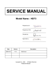
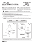
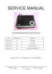
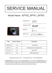
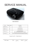
SERVICE MANUAL
Model Name : EP1690 / OP1280 / OP1140
Prepared by SI :
______________________________________
Prepared by TSE :
_______________________________________
Check by :
______________________________________
Approved by :
______________________________________
Date
Revise Version
2006/06/26
V1.0
2009/02/20
V2.0
Description
Initial Issue
Add EP1690 extended models: OP1280, OP1140
Copyright February, 2009. All Rights Reserved
P/N: 36.85F03G001
Preface
This manual is applied to EP1690 / OP1280 / OP1140 projection system. The manual
gives you a brief description of basic technical information to help in service and maintain
the product.
Your customers will appreciate the quick response time when you immediately identify
problems that occur with our products. We expect your customers will appreciate the service that you offer them.
This manual is for technicians and people who have an electronic background. Please
send the product back to the distributor for repairing and do not attempt to do anything that
is complex or is not mentioned in the troubleshooting.
Notice: The information found in this manual is subject to change without prior notice. Any subsequent
changes made to the data herein will be incorporated in future edition.
EP1690 / OP1280 / OP1140 Service Manual
Copyright February, 2009
All Rights Reserved
Manual Version 2.0
i
EP1690 / OP1280 / OP1140
Table of Content
Chapter 1 Introduction
1-1
Highlight
Compatible Mode
1-1
1-3
Chapter 2 Disassembly Procedure
2-1
Equipment Needed
Remove Lamp Module
Remove Top Cover Module
Remove Top Shielding Module
Remove Keypad Board and Keypad Button
Remove IR Receiver
Remove IO Cover
Remove Light Cut Mylar
2-1
2-2
2-3
2-4
2-5
2-6
2-7
2-8
Remove Airduct Module
Remove Isolator Mylar
Remove Main Board
Remove Blower Duct
Remove Side Shielding Module
Remove Speaker
Remove Blower
Disassemble Lamp Driver Module
Disassemble LVPS Module
Disassemble Power Module Holder
Disassemble Fan Module
Remove Wire 2P#22 220C
Remove Engine Module
Remove Thermal Switch
2-9
2-10
2-11
2-12
2-13
2-14
2-15
2-16
2-17
2-18
2-19
2-20
2-21
2-22
Remove Heatsink and 2 Springs
Remove DMD Chip
Disassemble Color Wheel and Photo Sensor Board
Remove Zoom Ring
Remove Focus Ring
Remove Blower
Disassemble Interrupt Switch
Remove Bottom Base
Remove Front Lower Panel
Remove Front Shielding Module
2-23
2-24
2-25
2-26
2-27
2-28
2-29
2-30
2-31
2-32
ii
EP1690 / OP1280 / OP1140
Chapter 3 Troubleshooting
3-1
Equipment Needed
Main Procedure
3-1
3-1
Chapter 4 Function Test & Alignment Procedure
4-1
Test Equipment Needed
Service Mode
Test Condition
4-1
4-1
4-2
Inspection Procedure
4-2
Chapter 5 Firmware Upgrade 5-1
Equipment Needed
Installation Procedure
USB Driver Upgrade Procedure
Firmware Upgrade Procedure
5-1
5-2
5-5
5-6
Chapter 6 EDID Key-in Procedure
6-1
EDID Introduction
Equipment Needed
Setup Procedure
EDID Key In Procedure
6-1
6-1
6-2
6-3
Appendix A
7-1
7-1
Exploded Overview
Appendix B
Serial Number System Definition PCBA Code Definition
iii
7-23
7-23
7-24
EP1690 / OP1280 / OP1140
Chapter 1
Introduction
1-1 Highlight
No
Item
Description
1
Weight
• < 7.2 lbs (7.128 lbs – 3.24kg)
2
Dimension (W x D x H) • 13.67 x 3.73 x 9.69 inches (347.3 x 94.7 x 246.2 mm)
3
Cooling system
•� ���������
Advanced ����
air ����
flow
•� ������
Three ������
motor �����
fans �����
(one �����
5020 ��������
Blower, ����
one �����
7025 ������
axial ������
fan
and one 4510 blower fan)
•� ������������
Temperature ��������
control ���������
circuits �����
with ���������
adaptive voltage
��������
control fan speed
•� ����
Max ������
touch ������������
temperature ��������
follows ������������������
UL60950 regulation
4
Lamp Door Protection
•� �����
Lamp ������
power �������
supply ������
shuts ����
off ��������������
automatically �����
when ������
door
open
5
Power supply
•� ������������������
Universal 100—240 VAC+/-10%,
������������ ������
50-60 ����
Hz ����������
with PFC
input
•� �����
220W ����
for ��������
Philips Lamp
����� at
��� normal
������� operation,
����������� 172W
����� at
�����
low power mode
6
Power Consumption
•� �����
272W ������
+-10% ����������
at 110Vac ���
& �����
265W ������
+-10% ���
at �������
220Vac
•����������������
< 12W(Stand by)
7
Input signal spec.
•� ������
Hsync �����������
Frequency: ������
15.75 ��
~ �����
91.1 ��������
kHz
•� ������
Vsync �����������
Frequency: ���
43 ��
~ ���
85 ��
Hz
•� ������
Video �������
Signal RGB
���� (PC)
����
Analog RGB: 0.7Vp-p, 75 ohm
Analog RGB: 1Vp-p, 75 ohm, Sync. Signal
Separate TTL H,V Sync.
Composite TTL Sync.
•� �����
Video
Composite video 1Vp-p,75 ohm
S-video Luminance 0.714Vp-p,75 ohm
S-video Chrominance: 0.286Vp-p,75 ohm
1-
EP1690 / OP1280 / OP1140
NO
8
Item
Brightness
9
Video compatibility
10
Control Keypad
11
Keystone
12
Contrast
13
14
15
16
Uniformity
Projection lens
Projection Image Size
Temperature
17
Altitude
18
MTBF
Description
•� �������������
Typical 2125 ����������������������
ANSI lm /Minimum 1900 ��������
ANSI lm
<Condition> Spoke light mode “White” on Service
Menu. (Bright mode)
•� �����������
Standards: �����������
(Should be frame
������ lock)
�����
NTSC: M,
PAL: B, D, G
HDTV: 720p, 1080i
Note: support 480i, 480p, 576i and 576p
•� ���������
8-button ������
keys:
Power/Standby
Menu button: Menu
Middle button: Enter
Left key for OSD menu/: Input source changed
Right key for OSD menu/: Automatic position &
fine sync function
Up key for OSD menu: Zoom in function when no OSD
menu
Up key for OSD menu: Zoom out function when no
OSD menu
LED of top keys
•� ����������
Vertical: ������
+- 10 ����
deg ����������������
(Desk-projecter angle)
������
•� ������������
Horizontal: +������
10 deg
���
•� �����
Full �����
on / �����
Full �������������
off :Typical �����
2000 ��: ���
1 ��������������
/Minimum 1300 :�� 1
����
(Spoke on/Spoke off)
•� ��������
Typical ������
Japan ����
80% ���������
/Minimum ����
65% ������
(Full ���
on)
•� ���
F/ ���������
2.5~2.8, ��f ��
= ���������
22.25 ~ ���������
26.69mm, ����
1.2X
• 36” to 291” Diagonal
• Operating: 5 -- 35°C
• Storage:
-10 -- 60°C
• Operating0~2,500 ft 5°C~35°C
2,500~5,000 ft 5°C~30°C
5,000~10,000 ft 5°C~25°C
• Storage
40,000 ft
• Operating more than 12,000 hours (90% Confidence
Level)
1-
EP1690 / OP1280 / OP1140
1-2 Computer Compatible
Compatibility
Resolution
V-Sync (Hz)
640 x 350
70
640 x 350
85
640 x 400
85
640 x 480
60
640 x 480
72
640 x 480
75
640 x 480
85
720 x 400
70
720 x 400
85
800 x 600
56
800 x 600
60
800 x 600
72
800 x 600
75
800 x 600
85
1024 x 768
60
1024 x 768
70
1024 x 768
75
1024 x 768
85
1280 x 720
60
1280 x 768
60
1280 x 768
85
1280 x 1024
60
1280 x 1024
75
SXGA+
1400 x 1050
60
UXGA
1600 x 1200
60
VGA
SVGA
XGA
WXGA*
WXGA
SXGA
1-
EP1690 / OP1280 / OP1140
Chapter 2
Disassembly Process
2-1 Equipment Needed
Item
Photo
Item
Screw Bit
(+) :107
Hex Sleeves
5mm
Hex
Sleeves
8mm
Tweezers
Photo
Note: As the process of OP1280 / OP1140 disassembling is the same as EP1690, we take EP1690
for example here.
2-
EP1690 / OP1280 / OP1140
2-2 Remove Lamp Module
No
Procedure
1 Unscrew 1 screw to remove
Lamp Cover
(as red circle)
Photo
Lamp Cover
2
Unscrew 2 screws to
remove Lamp Module
(as red circle)
Lamp
2-
EP1690 / OP1280 / OP1140
2-3 Remove Top Cover Module
No
Procedure
1 (1) Unscrew 5 screws
(as red circle)
Photo
(2) Release 11 tennons
(as blue circle)
(3) Unplug FPC Wire and
IR Wire
(as yellow square)
(4) Remove Top Cover
Module
Top Cover Moule
2-
EP1690 / OP1280 / OP1140
2-4 Remove Top Shielding Module
No
Procedure
1 (1) Take off FPC Wire directly
Photo
(2) Unscrew 4 screws
(as red circle)
(3) Release 2 tennons
(as blue circle)
(4) Remove Top Shielding
Module
FPC Wire
Top Shielding Module
2-
EP1690 / OP1280 / OP1140
2-5 Remove Keypad Board and Keypad Button
No
Procedure
1 (1) Unscrew 1 screw
(as red circle)
Photo
(2) Remove Keypad Board
and Keypad Button directly
Keypad Board
Keypad Button
2-
EP1690 / OP1280 / OP1140
2-6 Remove IR Receiver
No
Procedure
1 (1) Take off Mylar and IR
Cover directly
Photo
(2) Remove IR Receiver
IR Receiver
Top Cover
2-
EP1690 / OP1280 / OP1140
2-7 Remove IO Cover
No
Procedure
1 (1) Unscrew 1 screw
(as red circle)
Photo
(2) Unscrew 8 hex screws
(as green circle)
(3) Remove IO Cover
IO Cover
2-
EP1690 / OP1280 / OP1140
2-8 Remove Light Cut Mylar
No
Procedure
1 Take off Light Cut Mylar
directly
(as red square)
Photo
Light Cut Mylar
2-
EP1690 / OP1280 / OP1140
2-9 Remove Airduct Module
No
Procedure
1 (1) Unscrew 3 screws
(as red circle)
Photo
(2) Remove Airduct Module
Airduct Module
2-
EP1690 / OP1280 / OP1140
2-10 Remove Isolator Mylar
No
Procedure
1 (1) Unplug 1 speaker wire
(as yellow square)
Photo
(2) Remove Isolator Mylar
directly
(as red square)
2-10
EP1690 / OP1280 / OP1140
2-11 Remove Main Board
No
Procedure
1 (1) Unscrew 5 screws
(as red circle)
Photo
(2) Unplug 6 connectors
(as yellow square)
(3) Unplug 1 connector
(as blue square)
(4) Remove 2 Mylars
directly
(as red square)
(5) Remove Main Board
Main Board
2-11
EP1690 / OP1280 / OP1140
2-12 Remove Blower Duct
No
Procedure
1 (1) Unscrew 1 screw
(as red circle)
Photo
(2) Remove Blower Duct
Blower Duct
2-12
EP1690 / OP1280 / OP1140
2-13 Remove Side Shielding Module
No
Procedure
1 (1) Unscrew 2 screws
(as red circle)
Photo
(2) Remove Side Shielding
Module
Side Shielding Module
2-13
EP1690 / OP1280 / OP1140
2-14 Remove Speaker
No
Procedure
1 (1) Unscrew 2 screws
(as red circle)
Photo
(2) Take off Speaker Holder
Rubber directly
(3) Remove Speaker
Speaker
2-14
EP1690 / OP1280 / OP1140
2-15 Remove Blower
No
Procedure
1 (1) Unscrew 3 screws
(as red circle)
Photo
(2) Remove Blower
Blower
2-15
EP1690 / OP1280 / OP1140
2-16 Disassemble Lamp Driver Module
No
Procedure
1 (1) Unscrew 2 screws
(as red circle)
Photo
(2) Unplug 2 connectors
(as yellow square)
(3) Remove Lamp Driver
Module
Lamp Driver Module
2
(1) Unscrew 3 screws
(as red circle)
(2) Take off Mylar directly
(as red square)
(3) Disassemble Lamp Driver
and Lamp Driver Holder
Lamp Driver
2-16
Lamp Driver Holder
EP1690 / OP1280 / OP1140
2-17 Disassemble LVPS Module
No
Procedure
1 (1) Take off Mylar directly
Photo
(2) Unscrew 5 screws
(as red circle)
(3) Unplug Thremal Switch
connectors
(as yellow square)
(4) Unplug Interrupt Switch
(as blue square)
(5) Remove LVPS Module
(as red square)
LVPS Module
2
(1) Unplug 2 connectors
(as yellow square)
(2) Remove LVPS
(as red square)
LVPS
2-17
EP1690 / OP1280 / OP1140
2-18 Disassemble Power Module Holder
No
Procedure
1 (1) Unscrew 3 screws
(as red circle)
Photo
(2) Take off Mylar directly
(3) Disassemble Power
Module Holder
(as red square)
Power Module Holder
2-18
EP1690 / OP1280 / OP1140
2-19 Disassemble Fan Module
No
Procedure
1 (1) Unscrew 2 screws
(as red circle)
Photo
(2) Disassemble Fan Module
Fan Module
2-19
EP1690 / OP1280 / OP1140
2-20 Remove Wire 2P#22 220C
No
Procedure
1 (1) Unscrew 2 screws
(as red circle)
Photo
(2) Remove Wire 2P#22 220C
Wire 2P#22 220C
2-20
EP1690 / OP1280 / OP1140
2-21 Remove Engine Module
No
Procedure
1 (1) Unscrew 4 screws
(as red circle)
Photo
(2) Remove Engine Module
Engine Module
2-21
EP1690 / OP1280 / OP1140
2-22 Remove Thremal Switch
No
Procedure
1 (1) Unscrew 1 screw
(as red circle)
Photo
(2) Remove Thremal Switch
Thremal Switch
2-22
EP1690 / OP1280 / OP1140
2-23 Remove Heatsink and 2 Springs
No
Procedure
1 (1) Unscrew 4 screws
(as red circle)
Photo
(2) Remove Heatsink and
2 Springs
Heatsink and 2 Springs
2-23
EP1690 / OP1280 / OP1140
2-24 Remove DMD Chip
No
Procedure
1 (1) Unscrew 4 hex screws
(as red circle)
Photo
(2) Remove DMD Chip
DMD Chip
2-24
EP1690 / OP1280 / OP1140
2-25 Disassemble Color Wheel and Photo Sensor Board
No
Procedure
1 (1) Unscrew 2 screws
(as red circle)
Photo
(2) Disassemble Color Wheel
and Photo Sensor Board
Color Wheel & Photo
Sensor Board
2-25
EP1690 / OP1280 / OP1140
2-26 Remove Zoom Ring
No
Procedure
1 Take off Zoom Ring directly
Photo
Zoom Ring
2-26
EP1690 / OP1280 / OP1140
2-27 Remove Focus Ring
No
Procedure
1 (1) Unscrew 3 screws
(as red circle)
Photo
(2) Remove Focus Ring
Focus Ring
2-27
EP1690 / OP1280 / OP1140
2-28 Remove Blower
No
Procedure
1 (1) Unscrew 3 screws
(as red circle)
Photo
(2) Remove Blower
Blower
2-28
EP1690 / OP1280 / OP1140
2-29 Disassemble Interrupt Switch
No
Procedure
1 (1) Unscrew 2 screws
(as red circle)
Photo
(2) Disassemble Interrupt
Switch
Interrupt Switch
2-29
EP1690 / OP1280 / OP1140
2-30 Remove Bottom Base
No
Procedure
1 (1) Unscrew 2 screws
(as red circle)
Photo
(2) Remove Bottom Base
Bottom Base
2-30
EP1690 / OP1280 / OP1140
2-31 Remove Front Lower Panel
No
Procedure
1 (1) Release 2 tennons
(as red circle)
Photo
(2) Remove Front Lower
Panel
Front Lower Panel
2-31
EP1690 / OP1280 / OP1140
2-32 Remove Front Shielding Module
No
Procedure
1 (1) Unscrew 2 screws
(as red circle)
Photo
(2) Remove Front Shielding
Module
Front Shielding Module
2-32
EP1690 / OP1280 / OP1140
Chapter 3
Troubleshooting
3-1 Equipment Needed
- PC or Pattern Generator
- DVD Player (Video, S-Video, Audio)
- Quantum Data 802B or CHROMA 2327
3-2 Main Procedure
No
Symptom
Procedure
1
No Power
- Ensure the Power Cord and AC Power Outlet are securely
connected
- Check Lamp Cover and Interrupt Switch
- Ensure all connectors are securely connected and aren’t
broken
- Check DC-DC
- Check Ballast
- Check Main Board
2
Auto Shut
Down
- Check LED Status
a. Lamp LED Light
- Check Lamp
- Check Lamp Driver
- Check Main Board
b. Temp LED Light
- Check Thermal Sensor
- Check Thermal Switch
- Check Fan
- Check Main Board
c. Color Wheel
- Check Color Wheel
- Check Photo Sensor
3-
EP1690 / OP1280 / OP1140
No
Symptom
Procedure
3
No Image
- Ensure the Signal Cable and Source work
(If you connect multiple sources at the same time,
use the “Source” button on the control panel to
swtich)
- Ensure all connectors are securely connected and
aren’t broken
- Check Main Board
- Check DMD Board
- Check Color Wheel
- Check DMD Chip
- Check Engine Module
4
No Light On
- Ensure all connectors are securely connected and
aren’t broken
- Check Lamp Module
- Check DC-DC
- Check Ballast
- Check Main Board
5
Mechanical Noise
- Check Color Wheel
- Check Fan Module
6
Line Bar / Line
Defect
- Check if the DMD Chip and the DMD Board are
assembled properly
- Check DMD Board
- Check DMD Chip
- Check Main Board
7
Image Flicker
- Do “Reset” of the OSD Menu
- Ensure the Signal Cable and Source work
- Check Lamp Module
- Check Color Wheel
- Check DMD Board
- Check Main Board
8
Color Abnormal
- Do “Reset” of the OSD Menu
- Adjust Color Wheel Index
- Check Main Board
- Check DMD Board
- Check Color Wheel
3-
EP1690 / OP1280 / OP1140
No
Symptom
Procedure
9
Poor Uniformity /
Shadow
- Ensure the Projection Screen without dirt
- Ensure the Projection Lens is clean
- Ensure the Brightness is within spec.
(Replace the Lamp if the Brightness is less
than spec.)
- Check Engine Module
10
Dead Pixel / Dust
(Out of spec.)
- Ensure the Projection Screen without dirt
- Ensure the Projection Lens is clean
- Clean DMD Chip and Engine Module
- Check DMD Chip
- Check Engine Module
11
Garbage Image
- Ensure the Signal Cable and Source work
- Check Main Board
- Check DMD Board
12
Remote Control
or Control Panel
Failed
- Remote Control
a. Check Battery
b. Check Remote Control
c. IR Receiver
- Control Panel
a. Check FPC
b. Check Keypad
c. Check Main Board
13
Function Abnormal
- Do “Reset” of the OSD Menu
- Check Main Board
- Check DMD Board
3-
EP1690 / OP1280 / OP1140
Chapter 4
Function Test & Alignment Procedure
4-1 Test Equipment Needed
- IBM PC with XGA resolution (Color Video Signal & Pattern Generator)
- DVD player with Multi-system (NTSC/PAL/SECAM), equipped “Component”, “S-Video”
and “Composite”
- HDTV Tuner or Source (480P, 720P, 1080i)
- Minolta CL-100
- Quantum Data 802B or CHROMA2327
- After changing parts, check the information below.
Change
Reset
Color
Parts
Version
PC
Video
Lamp
Factory
Wheel
EDID
Update
Calibration Calibration
Use
Reset
Index
Update
Time
Main
Board
v
Firmware
v
Color
Wheel
v
v
v
v
v
v
v
v
v
Lamp
Module
v
Note: If Color appears abnormal after changing Main Board Module, please do Color
Wheel index adjustment.
4-2 Service Mode
No
Item
Step
1
Service
Mode
1. Turn on the projector.
2. Press these buttons sequentially: Power, Source, Source, Up.
2
Factory
Reset
After final QC step, we have to erase all saved change again and
restore the factory defaults. The following actions will allow you to
erase all end-users’ settings and restore the original setting:
1. Please get into Menu.
2. Use OSD to reset.
4-
EP1690 / OP1280 / OP1140
4-3 Test Condition
- Circumstance Brightness : Dark room less than 0.5 lux.
- Inspection Distance : 1.5 M~3 M for functional inspection
- Screen Size : 60 inches diagonal (wide)
- After repairing each EP1690 / OP1280 / OP1140, the unit should be burn-in (Refer to the
table below).
Symptom
Burn-in Time
Normal Repair
2 Hours
NFF
4 Hours
Auto Shutdown
6 Hours
4-4 Inspection Procedure
No
Step
Specification
Procedure
Frequency
and Tracking
Eliminate visual
wavy noise by
Rsync, Frequency or Tracking
selection.
- Test Signal:
1024x768@60Hz
- Test Pattern: General-1
- check and see if image
sharpness and focus
are well-performed.
- If not, re-adjust by the
following steps:
(1) Select “Frequency”
function to adjust
the total pixel number
of pixel clock in one
line period.
(2) Then, select
“Tracking” function
and use right or left
arrow key to adjust
the vague to
minimize video flicker.
Boundary
Horz. And Vert.
position of
video should be
adjustable to
be the screen
frame.
- Test Signal:
1024x768@60Hz
- Test Pattern: General
- Adjust Resync or
Frequency / Tracking /
H. Position / V. Position
to the inner of the screen.
1
2
4-
Photo
EP1690 / OP1280 / OP1140
No
3
Step
Focus
Specification
The text in the
corner should
be clear after
adjust the focus
ring.
Procedure
Photo
- Test Signal:
1024x768@60Hz
- Test Pattern: Ful-xga
- Adjust the center
clearly; meanwhile,
one slightly vague
corner in the image is
allowed.
- Test Signal: 720p,
1080i
- Test Pattern: Master
- Equipment: Quantum
Data 802B or
CHROMA2327
4
5
HDTV
Color
Performance
No discolor
Note:
*Please refer to4-2 to
get into Service Mode.
Use 720P&1080i
signal, Master pattern to
do HDTV test. Color cannot discolor to purple and
blue. If the line discolors,
it’s normal.
If the test result was in
discoloration or flickering,
it’s ng.
- Test Signal:
1024x768@60Hz
- Test Pattern: PANAICON Pattern & 64
GRAYS RGBW
- Please check and
ensure if each color is
normal and
distinguishable.
- If not, please adjust
color index of the
Engineering Mode.
- Fix OSD to re-sync or
track Frequency.
4-
EP1690 / OP1280 / OP1140
No
Step
Specification
Procedure
Screen
Uniformity
Should be
compliant with
60%. (Minimum)
- Test Signal:
1024x768@60Hz
- Test Pattern: Full White
Pattern & Full Black
Pattern
- Please check and ensure
the unit is under the spec.
- Please check and see if
it’s in normal condition
- If not, please return the
unit to repair area
6
7
Light Leak
The unit can’t
accept the leakage is brighter
than Gray 10
pattern
Photo
- Test Signal:
1024x768@60Hz
- Test Pattern: Gray 10
Pattern
- Please check and see if
the light leaks *Note
- The unit cannot accept
the leakage is brighter
than Gray 10 Pattern
Note:
Light leak on reflective
edge, eyecatcher, bond
wires and exposed metal.
4-
EP1690 / OP1280 / OP1140
No
8
Step
Calibration
Specification
Calibration
Pattern should
be in full screen
mode
Procedure
Photo
- Once Main Board is
changed, firmware
upgrade, YPbPr
Calibration & PC
Calibration should be done
as well
- YPbPr Calibration
- Test Signal: 480P
- Test Pattern: TV BAR
- PC Calibration
- Test Signal:
1024x768@60Hz
- Test Pattern: White (up)
Black (down)
Note:
1. Calibration Pattern should
be in Full Screen Mode.
2. Please refer to 4-2 to
get into Service Mode
and Factory Reset for
getting into Service Mode.
3. Choose and access
YPbPr Calibration & PC
Calibration for correction
in Service Mode. Choose
“Menu” to leave the
Service Mode after all
9
R, G,
B and
White
Color
Performance
Each R, G, B
color should be
normal without
color abnormal
issue.
- Test Pattern: R,
G, B and White
Color
4-
EP1690 / OP1280 / OP1140
No
Specification
Procedure
Dead Pixel
(Bright pixel)
Cannot accept any
bright pixel
- Test Pattern: Full
Black
Dead Pixel
(Dark pixel)
The numbers of
dead pixel should
be smaller or
amount to 6 pixel.
- Test Pattern: Full
White
11
Blemish
(Bright)
The bright blemish
cannot be accepted if the problem
appear with Gray
30 pattern
- Test Pattern:
Gray 30
12
Blemish
(Dark)
The dark blemish
cannot be accepted if the problem
appear with Blue
60 pattern.
- Test Pattern:
Blue 60
10
Step
4-
Photo
EP1690 / OP1280 / OP1140
Chapter 5
Firmware Upgrade
5-1 Equipment Needed
Software: (DDP 3020- USB)
- DLP Composer Lite v6.0
- Firmware
- Library file
Note: The FW upgrade procedure for OP1280 / OP1140 is the same as EP1690, here we take EP1690 for example.
Hardware:
Item
Photo
Item
Projector
(EP1690)
USB
Cable
Power
Cord
PC or
Laptop
5-
Photo
EP1690 / OP1280 / OP1140
5-2 Installation Procedure
DLP Composer Lite Setup Procedure
No
Step
Procedure
1
Execute
FW
program
Choose
“DLP Composer Lite
v6.0 Setup”
program.
2
Next
Click “Next” button.
3
Next
1. Reading the
“License
Agreement” rules.
2. Choose “I accept
and agree to be
bound by all the
terms and
conditions of this
License
Agreement” icon.
3. Click “Next”
button.
4
Next
Click “Next” button.
Photo
5-
EP1690 / OP1280 / OP1140
No
Step
Procedure
5
Next
Click “Next” button.
6
Next
Click “Next” button.
7
Processing
Waiting for setup.
Photo
5-
EP1690 / OP1280 / OP1140
No
Step
Procedure
8
Next
Click “Next” button.
9
Finish
Click “Yes” button to
restart computer.
Photo
5-
EP1690 / OP1280 / OP1140
5-3 USB Driver Upgrade Procedure
No
1
Step
Execute
Program
Procedure
Photo
Execute the C:\
Program files\DLP
Composer\usbupdata.cmd
Note:
The “DLP Composer”
program must be
closed first.
2
Type any
key to
continue
Press any key to
continue. Then, wait
for about 1 minute.
3
Update
Successfully
Click “OK”. The
USB driver is updated successfully.
Note:
If you have installed
the USB driver, there
is no need to perform
this action.
5-
EP1690 / OP1280 / OP1140
5-4 Firmware Upgrade Procedure
No
1
Step
Set-up
Procedure
Photo
1. Hold on “Enter”
button and plug in
Power Cord.
2. Wait for about 5
seconds.
3. Once Lamp, Temp
LED lights up,
plug in USB Cable
into the Projector and
link to PC USB.
Note:
The system fan will not
function. The light will not
function as well.
2
Next
Execute the “DLP
ComposeTM” file.
3
Next
Click “Edit” and
“Preferences”.
5-
EP1690 / OP1280 / OP1140
No
Step
Procedure
4
Next
1. Click “Library”.
2. The library path
located in the
default
installation
directory is C:\
Program Files\
DLP Composer.
If not, press
“Browse” to select
the right path.
5
Next
1. Select “Edit\
Preferences\
Communications”
and choose
“USB”.
2. Click “OK”.
Photo
Note: USB Device
Identification
Vendor: 0x451
Product: 0x2000
5-
EP1690 / OP1280 / OP1140
No
6
Step
Next
Procedure
Photo
1. Choose “Flash
Loader”
2. Click “Browse” to
search the firmware
file. (EP1690)
3. Select the item “Skip
Boot Loader Area
(load all but the first
64KB).”
4. Click “Reset Bus” to
erase the flash
memory.
Note:
If the error message “cannot open USB driver - No
projectors found” appears,
please replug the USB
Cable and check driver
again and then re-do the
above procedures.
7
Next
Note:
1. If the firmware is
ready, click “Start
Download” to process
the firmware upgrade.
2. Click “Yes” to erase
the flash memory.
2
1
5-
EP1690 / OP1280 / OP1140
No
Step
Procedure
Photo
8
Next
Proceeding Picture
9
Next
1. When Firmware
Upgrade Process is
finished, the LED
power light on.
2. Unplug USB Cable
and Power Cord.
Re-plug in Power
Cable.
10
Check
Firmware
Restart the unit and get
into the Service Mode
to check the Firmware
Version.
Note:
For getting into Service
Mode, please refer to
Chapter 4 Function Test
and Alignment Procedure.
5-
EP1690 / OP1280 / OP1140
Chapter 6
EDID Upgrade
6-1 EDID Introduction
Extended Display Identification Data is a VESA standard data format that contains
basic information about a display device and its capabilities, including vendor information,
maximum image size, color characteristics, factory pre-set timings, frequency range limits,
and character strings for the monitor name and serial number.
The information is stored in the display and is used to communicate with the system
through a Display Data Channel (DDC), which sites between the display device and the PC
graphics adapter. The system uses this information for configuration purposes, so the monitor
and system can work together.
Note:
If a display device has digital input ports, like DVI or HDMI, but without EDID in its main
board, the display device will show no image while the input source is digital signal. The EDID Upgrade
procedure for OP1280 / OP1140 is the same as EP1690, we take EP1690 for example here.
6-2 Equipment Needed
Software:
- EDID Program (Generic V0.51)
- EDID Table (*.ini)
Hardware:
- Generic Fixture for EDID Key-in
(Fixture: JP3 must be closed)
Item
Photo
Item
RS-232
Cable
(F - M)
Power
Adapter for
Fixture
DVI Cable
Generic
Fixture
VGA Cable
Power Cord
6-
Photo
EP1690 / OP1280 / OP1140
Item
Photo
Item
Photo
One
additional
monitor
(for checking the
program
execution)
PC
Projector
6-3 Setup Procedure
No
1
Step
Connect
All Ports
Procedure
Photo
1. Power Adapter to Fixture JP1
2. Fixture P1 to PC COM1 Port
3. Fixture P2 to Projector
Analog Port
4. Fixture P3 to Projector Digital
Port
Adapter
JP1
P1
RS-232 Cable
2
Power On
Fixture
To Digital Port
P3
P2
To Analog Port
Power on Fixture
6-
EP1690 / OP1280 / OP1140
6-4 EDID Key-In Procedure
No
Step
Procedure
1
Execute
EDID
Program.
Click on “EDID” to
execute EDID
Program.
2
Choose
Model
1. In the Port
Selection Bar,
please choose
the Port that you
use. Ex: If you
use “COM 1”,
choose COM 1 in
the Port selection.
2. Click on “Model”.
3. Choose the EDID
that responses to
the model that
you choose.
Photo
2
1
3
6-
EP1690 / OP1280 / OP1140
No
3
4
Step
Key in
Serial
Number
Change
Cable to
Analog
Procedure
1. Key in the Serial
Number into the
Barcode blank
space.
2. In “Write Source
Select”, make a
check in “VGA”
and “DVI”.
3. Click “Program”.
Photo
1
3
3
2
2
“Please change the
Cable to Analog”
message is shown
on the screen, then
click “OK”.
Note:
“RUN” message will
appear on the screen.
5
Change
Cable to
Digital
“Please change the
Cable to Digital”
message is shown
on the screen, then
click “OK”.
Note:
“RUN” message will
appear on the screen.
6
Finished
When the EDID
program is completed, the message,
“OK”, will appear on
the screen.
6-
EP1690 / OP1280 / OP1140
Appendix A
Exploded Overview
D.C. EP1690 FOR OPTOMA
7-1
EP1690 / OP1280 / OP1140
Item
P/N
Description
1
52.83F13G001
TOP COVER TO ENGINE SILICON RUBBER
30(L)X15(W)X14.6(H) HD72
2
61.88511G001
HEX SPACER M3 H=52mm L=4mm AL PD726
3
70.83F20G001
AXIAL FAN MODULE HD72
4
51.85F02G001
YM10 ZOOM RING PC+ABS MB1700 FOR EP1690
5
51.83F11G021
LAMP COVER PC EP1690
6
51.83R06G001
BLOWER DUCT PC EP1690
7
51.83F31G002
ENGINE LIGHT CUT MYLAR FRPP 0.43t HD72
8
61.00018G002
LOCK SCREW PAN MECH M3*8.5-3.5 BLACK
9
70.85F01G001
ASSY TOP COVER MODULE EP1690
10
70.85F02G001
ASSY BOTTOM COVER MODULE EP1690
11
75.83R09G011
BUY ASSY IO COVER MODULE EP1690
12
70.85F03G001
ASSY LAMP MODULE(PHILIPS-E19-220) EP1690
13
70.85F04G001
ASSY PCB MAIN BD MODULE EP1690
14
70.85F05G001
ASSY POWER MODULE EP1690
15
70.85F09G001
ASSY ENGINE & BOTTOM BASE MODULE EP1690
17
75.83F01G001
BUY ASSY AIRDUCT MODULE HD72
18
85.005AGG408
SCREW HEX I/O #4-40 H4xL8 Ni Nylok
19
85.1F123G060
SCREW PAN MECH W/SF M3*6 Ni
21
85.1A126G030
SCREW PAN MECH M2.6*3 Ni
22
85.WA123G080
SCREW PAN TAP M3*8 Ni
23
85.3A122G040
SCREW CAP MECH M2*4 Ni
24
70.85F08G001
ASSY SIDE SHIELDING MODULE EP1690
7-2
EP1690 / OP1280 / OP1140
ASSY TOP COVER MODULE EP1690
7-3
EP1690 / OP1280 / OP1140
Exploded Parts List
Item
P/N
Description
1
42.83F04G001
CABLE FFC 14P PITCH=1.0mm H72
2
51.83F01G031
TOP COVER PC MN3600 EP1690
3
51.83F07G001
KEYPAD BUTTON PC H72
4
51.83F08G011
IR FRONT LENS EP747
5
51.83F26G001
FRONT IR MYLAR H72
6
51.83F29G001
KEYPAD LED LENS HOLDER PC H72
7
75.85F06G001
BUY ASSY TOP SHIELDING MODULE EP1690
8
80.85F03G001
PCBA KEYPAD BD FOR EP1690
9
80.83F04G001
PCBA IR SENSOR BD H72
10
85.1A123G040
SCREW PAN MECH M3*4 Ni
11
52.83F14G001
TOP COVER IR INSULATOR RUBBER HD72
12
51.81541G001
TAPE 3M J350 17*30mm
13
41.81R15G001
EMI GASKET TAPE 0.13T 15MM*30MM DV10
7-4
EP1690 / OP1280 / OP1140
ASSY BOTTOM COVER MODULE EP1690
Item
P/N
Description
1
51.83F12G021
FRONT LOWER PANEL PC MN3600 EP1690
2
75.85F02G001
BUY ASSY BOTTOM COVER MODULE EP1690
3
75.83F05G001
BUY ASSY FRONT SIDE SHIELDING H72
4
85.WA123.080
SCREW PAN TAP M3*8 Ni
7-5
EP1690 / OP1280 / OP1140
ASSY LAMP MODULE
Item
P/N
Description
1
35.81R04G001
LABEL LAMP CHANGE CAUTION DV10
2
23.85F15G001
PHILIPS E19 220W/170W 1.0
3
51.80J02G002
LAMP BOTTOM 739 PPS
4
52.85F04G001
SILICON RUBBER FOR LAMP EP1690
5
52.80W12G001
LAMP INSULATOR SILICON RUBBER 2300MP
6
61.00018G002
LOCK SCREW PAN MECH M3*8.5-3.5 BLACK
7
61.80W16G003
LAMP INSULATOR AL NITTO 5011N 2300MP
8
61.85F01G001
LAMP HOLDER Mg (PHILIPS) EP1690
9
61.85F04G001
LAMPBRACKET SUS301 0.3t EP1690
10
61.83F10G001
LAMP MESH OUT OSRAM SUS301 t=0.1 H72
11
61.83F11G001
LAMP ANTIGLASS LAMP SUS301 t=0.25 H72
12
23.80S10G011
LAMP COVER GLESS OF DP739 SERIES WITH MAR
13
61.87125G001
LAMP HADNLER SUS304
14
85.1A626G050
SCREW PAN MECH M2.6*5 BLACK NYLOK
15
85.1F123G060
SCREW PAN MECH W/SF M3*6 Ni GREEN
16
42.80W11G002
OUTSIDE W.A. 70mm FOR LAMP 2300MP ACES
7-6
EP1690 / OP1280 / OP1140
ASSY PCB MAIN BD MODULE EP1690
Item
P/N
Description
1
80.85F02G001
PCBA MAIN BD ENTEK FOR EP1690
2
51.85F03G001
MB UP INSULATOR MYLAR C850 0.1t EP1690
3
51.85F04G001
MB DOWN INSULATOR MYLAR FRPP 0.43t EP1690
4
51.85F05G001
MB DOWN INSULATOR I/O MYLAR FRPP 0.43t EP1690
5
41.85A12G001
EMI COPPER FOIL/26*26
7-7
EP1690 / OP1280 / OP1140
ASSY POWER MODULE EP1690
Item
P/N
Description
1
85.1F123G060
SCREW PAN MECH W/SF M3*6 Ni
2
70.85F06G001
ASSY LAMP DRIVER MODULE EP1690
3
51.83R10G001
LAMP DRIVER HOLDER MYLAR FORMAX EP747
4
70.85F07G001
ASSY LVPS MODULE EP1690
5
51.00001G001
CABLE TIE PG-YJ-80
7-8
EP1690 / OP1280 / OP1140
ASSY LAMP DRIVER MODULE EP1690
Item
P/N
Description
1
51.83F20G001
LAMPDRIVER HOLDER PC+ABS HD72
2
85.1F123G060
SCREW PAN MECH W/SF M3*6 Ni
3
42.81R11G001
W.A.#28 5P LAMPDRIVER TO MAIN BOARD 170mm DV10
4
75.85F01G001
ASSY PHILIPS LAMP DRIVER 220W
5
42.85F01G001
ASSY LAMP DRIVER(PHILIPS) TO LAMP W.A. EP1690
6
51.85F06G001
LAMP DRIVER INSULATOR MYLAR FRPP 0.43T EP1690
7-9
EP1690 / OP1280 / OP1140
ASSY LVPS MODULE EP1690
Item
P/N
Description
1
75.85F08G001
BUY ASSY LVPS SHIELDING MODULE EP1690
2
51.83R08G001
POWER SHIELDING FORMAX MYLAR EP747
3
75.85F03G001
BUY ASSY POWER SHIELDING MODULE EP1690
4
85.1C224G050
SCREW PAN MECH M4*5 COLOR W/TOOTH WASHER
5
85.1F123G060
SCREW PAN MECH W/SF M3*6 Ni GREEN
6
70.85F14G001
ASSY SUB LVPS MODULE EP1690
7
52.83R17G001
GR-d 29.5*29.5*3.5 THERMAL PAD
8
41.85F05G001
EMI GASKET 5*170MM
7-10
EP1690 / OP1280 / OP1140
ASSY SIDE SHIELDING MODULE EP1690
Item
P/N
Description
1
75.85F04G001
BUY ASSY SIDE SHIELDING MODULE EP1690
2
49.83J03G001
MISC 45X10 DMD BLOWER,SUNON B1245PFV-8
3
85.1F123G060
SCREW PAN MECH W/SF M3*6 Ni GREEN
4
49.85F01G001
SPEAKER 12ohm 3W 260mm EP1690
5
85.3A122G080
SCREW CAP HEAD MECH M2*8 GREEN
6
52.85F02G001
SPEAKER HOLDER RUBBER EP1690
7
52.85F03G001
SCREW SILCON RUBBER D6.00*D2.00 T=2.00 EP1690
7-11
EP1690 / OP1280 / OP1140
ASSY ENGINE & BOTTOM BASE MODULE EP1690
7-12
EP1690 / OP1280 / OP1140
Item
P/N
Description
1
41.85F09G001
EMI GASKET W10*H1*L78 MM
2
51.83F33G001
LENS DOWN LIGHT CUT MYLAR FRPP 0.43t HD72
3
41.83F16G001
GASKET/W*10 H*10 L*40
4
41.85F12G001
EMI GASKET W3*H6*L72 MM
5
61.81R06G001
M/B STAND BRACKET AL 5052 t=1.0 & STEEL HS DV10
6
70.85F10G001
ASSY ENGINE MODULE EP1690
7
70.83F18G001
ASSY BOTTOM BASE MODULE DV10/H72
8
85.1F123G060
SCREW PAN MECH W/SF M3*6 Ni
7-13
EP1690 / OP1280 / OP1140
ASSY ENGINE MODULE EP1690
7-14
EP1690 / OP1280 / OP1140
Item
P/N
Description
1
11.009F0G007
CNNT F 230P FOR 720P LGA DMD SOCKET PE02032303040-10; FOXCO
2
41.81R17G001
EMI GASKET TAPE 0.13t FOR ENGINE DV10
3
41.83F05G001
GASKET/(L*45,W*7,H*10)
4
48.83FDMGD01
DMD 1280*768 PIXEL 0.65 WXGA 12%%176 LVDS TYPE A
5
51.80B31G002
DMD INSULATOR MYLAR 0.435t T90
6
51.80W33G001
ENGINE BOTTOM MIRROR1 TAPE 3M-J350 2300MP
7
52.80J01G001
DMD ANTIDUST RUBBER 739 SILICONE RUBBER
8
52.87130G001
RUBBER BLOWER 595925
9
52.87319G001
DMD THERMAL PAD 18*13*0.5t
10
61.80J10G001
DMD LIGHT MASK 739 SUS301
11
61.88605G001
DMD HEATSINK A1070 Ivy10X "GREEN"
12
61.80J48G002
DMD HEATSINK BACKER PLATE A6061 739
13
61.88608G001
DMD HEATSINK SPRING PLATE SUS301 0.4t Ivy10X
14
61.88611G001
DMD SCREW Ivy10X
15
70.85F11G001
ASSY SUB ENGINE MODULE EP1690
16
80.85F01G001
PCBA DMD BD WXGA FOR EP1690
17
85.1A523G040
SCREW PAN MECH M3*4 NYLOK
7-15
EP1690 / OP1280 / OP114
ASSY SUB ENGINE MODULE EP1690
7-16
EP1690 / OP1280 / OP1140
Item
P/N
Description
1
23.83J06G001
GLASS RELAY LENS
2
23.80S20G001
CONDENSER L2 OF DP739 SERIES
3
23.80S20G011
CONDENSER L3 OF DP739 SERIES "GREEN''
4
52.80J03G001
LENS ANTIDUST 739 SILICONE RUBBER
5
52.81R12G001
RELAY ANTIDUST YM08 739 SILICONE RUBBER
6
52.81R18G001
PORON ENGINE TO DUCT DV10
7
61.80J05G002
ROD SPRING 739 SUS301 0.25t
8
61.83F14G001
ROD BRACKET PLATE AL t=0.5mm 720P H72
9
70.85F12G001
ASSY OPTICAL LENS MODULE EP1690
10
70.85F13G001
ASSY COLOR WHEEL MODULE EP1690
11
70.83F15G001
ASSY ROD MODULE H72
12
70.85F16G001
PRE ASSY ENGINE BASE MODULE EP1690
13
70.83F17G001
PRE ASSY ENGINE BOTTOM MODULE EP739
14
85.1A326G060
SCREW PAN HEAD MECH M2.6*6 BLACK
15
85.1A526G060
SCREW PAN MECH M2.6*6 Ni NYLOK
16
85.1A626G040
SCREW PAN MECH M2.6*4 BLACK NYLOK
17
85.1F126G060
SCREW PAN MECH W/SF M2.6*6 Ni
18
75.80W15G002
BUY ASSY ZOOM RING STOP EMI MODULE 2300MP
7-17
EP1690 / OP1280 / OP1140
ASSY OPTICAL LENS MODULE
Item
P/N
Description
1
23.83F01G002
YM10 PROJECTION ZOOM LENS WITH MASK FOR 739
series,F/2.5~F/2.8
2
51.83F06G011
YM10 FOCUS RING PC+ABS MB1700 EP1690
3
85.WA321G040
SCREW PAN TAP M1.7*4 BLACK
7-18
EP1690 / OP1280 / OP1140
ASSY COLOR WHEEL MODULE
Item
P/N
Description
1
23.83F19G001
COLOR WHEEL R92/G83/W110/B75, SLEEVE BEARING OF
DP739 SERIES
2
61.80J08G002
CW HOLDER 739 SECC 1.2t
3
52.83615G001
COLOR WHEEL DISC RUBBER, EzPro755 "GREEN"
4
61.83628G002
COLOR WHEEL SHOULDER SCREW NICKEL M2*4.8
FILLIST
5
80.83F07G001
PCBA PHOTO SENSOR BD HD72
6
85.1A626G040
SCREW PAN MECH M2.6*4 BLACK NYLON
7
51.80J38G002
MYLAR CW SUPPORT 739 FRPP 0.125t
7-19
EP1690 / OP1280 / OP1140
ASSY SUB LVPS MODULE
Item
P/N
Description
1
42.81R13G001
W.A. #28 2P LIMITE SWITCH EXTENTION CABLE 115mm
DV10
2
42.85F02G001
W.A. 16P 200mm LVPS TO M/B EP1690
3
42.89602.001
W.A. 3P #20 180mm LAMP DRIVER TO LAMP EP759
4
70.85F17G001
ASSY SUB LITEON LVPS EP1690
7-20
EP1690 / OP1280 / OP1140
PRE ASSY ENGINE BASE
Item
P/N
Description
1
61.80J01G001
ENGINE BASE 739 Mg ALLOY "GREEN"
2
85.1A626G040
SCREW PAN MECH M2.6*4 BLACK NYLON
3
52.80J02G002
OFF LIGHT ISOLATOR 739 SILICONE RUBB
4
61.80J39G001
OFF LIGHT PLATE AL VULCAN-1
5
87.FL030G008
WASHER FLAT 7*3.1*0.8t PC PINGOOD WS-1M "GREEN"
6
85.1A326G060
SCREW PAN HEAD MECH M2.6*6 BLACK
7
61.80J07G001
SPRING MIRROR2 739 SUS301 0.25t "GREEN"
8
23.80J02G011
REFLECTION MIRROR2 OF DP739 SERIAL "GREEN"
9
23.80S10G001
UV/IR FILTER OF DP739 SERIES "GREEN"
10
61.80J02G001
UVIR HOLDER 739 SUS301 0.3t "GREEN"
11
51.80W34G001
ENGINE BASE MIRROR2 TAPE 3M-J350 2300MP "GREEN"
12
51.81542G001
TAPE 3M J350 17*15mm "GREEN"
13
61.85F06G001
BLOWER FAN DUCT PHILIPS E19-220 AL-ADC12 EP1690
14
85.5A126G040
SCREW BINDING MECH M2.6*4 Ni "GREEN"
7-21
EP1690 / OP1280 / OP114
ASSY SUB LITEON LVPS
Item
P/N
Description
1
75.85F05G001
ASSY LITEON LVPS EP1690
2
41.85F07G001
EMI SPRING
7-22
EP1690 / OP1280 / OP1140
Appendix B
I. Serial Number System Definition
Serial Number Format for Projector
1
: MM = Made in where (ex: CN = Made in China)
2
:
Area Code
3
:
BBBBB = MFG ID
4
:
Y = Last number of the year (ex: 2006 - 6)
5
:
Month of year (Jan = 1, Feb = 2,...Oct = A, Nov = B, Dec = C)
6
:
L = MFG Date
7
:
Serial code (from 0001~)
7-23
EP1690 / OP1280 / OP1140
II. PCBA Code Definition
PCBA Code for Projector
A B
3
2
1
XXXXXXXXXX C XXX
: ID
2
:
Vendor Code
3
:
P/N
4
:
Revision
5
:
Date Code
6
:
S/N
5
6
C: M/B
B: DMD/ B
1 4
EEEE
7-24
EP1690 / OP1280 / OP1140
*Reader’s Response*
Dear Readers:
Thank you for your backing our service manual up. In order to refine our content of the
service manual and satisfy your requirement. We expect you can offer us some precious
opinions for reference.
Assessment:
A. What do you think about the content after reading EP1690 / OP1280 / OP1140 Service
Manual?
Unit
Excellent
Good
Fair
Bad
1. Introduction
2. Disasaembly Procedure
3. Troubleshooting
4. Function Test & Alignment Procedure
5. Firmware Upgrade Procedure
6. DDC key-in Procedure
7. Appendix
B. Are you satisfied with the EP1690 service manual?
Item
1. Service Manual Content
2. Service Manual Layout
3. The form and listing
Excellent
Good
Fair
Bad
C. Do you have any other opinion or suggestion about this service manual?
Reader’s basic data:
Name:
Company:
Add:
Tel:
E-mail:
Tile:
Fax:
After your finishing this form, please send it back to Coretronic Customer Service Dept.
by fax: 886-3-563-5333.
7-25
EP1690 / OP1280 / OP1140