1
Electrical Interface
Power and Ground Signals
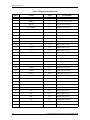
The interface includes seven ground signals and two 3.3V signals. The recommended
maximum current an expansion pack can draw from the VDD pins is 300 mA. If an expansion
pack requires more than 300 mA peak or requires a voltage other than 3.3V, it should include
its own power supply and/or battery and charging circuit. The power and ground pins
protrude 0.5 mm farther than the other signals on the main unit connector. This provides
power and ground to the expansion pack before the other signals make a connection.
When an expansion pack is first connected to the main unit, the expansion pack is
recommended to draw no more than 10 mA from the VDD pins for identification. Once the
main unit asserts OPT_ON, an expansion pack can draw the full 300 mA from the main unit.
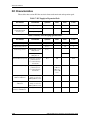
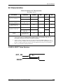
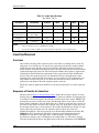
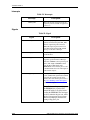
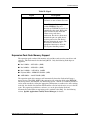
Table 6 (Expansion Pack Current consumption) shows the maximum peak current
consumption for an expansion pack given each state of OPT_ON.
Table 6: Expansion Pack Current Consumption
Expansion Pack Current
Consumption from VDD
OPT_ON = Low
OPT_ON = High
Approx. 10 mA
300 mA (max recommended)
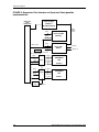
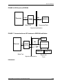
The expansion pack should use the power, ground and OPT_ON signals to detect whether it
is connected to the main unit, so it can enable the power supply and other functions on the
expansion pack.
A_GND is the ground associated with the analog, audio portion of the main unit. It
is connected only to expansion packs that use the A-OUTR and A_OUTL signals
and should route directly to the analog, audio section of the expansion pack. It is
very important not to couple digital noise into A_GND (i.e., connect A_GND to digital ground). If the audio signals are not used by an expansion pack, A_GND is not
connected.
Miscellaneous Signals
The expansion pack interface also includes other signals to provide insertion/removal
detection, reset and interrupt functions. INT_OP is an active high signal that allows the
expansion pack to interrupt the processor for various functions such as event notification,
data transfer, etc. This signal is pulled down on the main unit. Please refer to Section 4,
Software Interface, for more details on the interrupt service routine and support.
The RESET signal is a general-purpose reset signal from the main unit and is an active high
signal. RESET is asserted only when an expansion pack is first connected to the main unit.
Its pulse width and duration are controlled by the EEPROM settings. Please refer to Chapter
4 (Software Interface) for details on programming the length of RESET.
A_OUTR and A_OUTL are line out signals from the right and left channels of main unit's
audio codec.
The OPT_ON signal notifies the expansion pack that it can turn on and run at full power.
When an expansion pack is first inserted, OPT_ON is low and the expansion pack should
draw a minimal amount of current for identification. When the OPT_ON signal is asserted,
the expansion pack can draw the recommended maximum allowed current from the VDD
pins.
3–18
iPAQ H3000 Series Expansion Pack Developer Guide