1
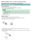
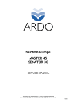
1
Engine Push-Start Module Installation
ENGINE PUSH-START
MODULE INSTALLATION
System Description
Advanced Keys’ Engine Push-Start Ignition Module with Toyota/Lexus OEM Push-Start
button should be used in conjunction with Advanced Keys Smart Keyless Entry System
for maximum vehicle security. An encrypted communication link between Push-Start
module and Keyless Entry modules will ensure the vehicle can only be started with a
valid access key. This system is also designed with dual-relay in mind as an exceptional
safety consideration. In the event of a relay failures, the backup relay will take over and
ensure continuous vehicle operation without interruption.
Note: Advanced Keys Engine push-start system is not intended for heavy duty and high
current ignition systems that requires greater than 30 Amps. Please verify vehicle’s
ignition current requirements and make sure it does not exceed this current limit.
Otherwise, current exceeding the relay rating will risk damaging both the controller and
the vehicle. If necessary, use additional external relays with switching capacity that
match the required ignition current of the vehicle when using this system.
1
1
Package Contents
The following is a list of components included in the kit:
Included Contents:
1 – Push-Start Module
1 – Push-Start Harness
1 – Push-Start Button
2 – Starter Ignition Relay
1 – User Manual/Installation Guide
INDUSTRY CANADA USER NOTICE (Canada)
Operation is subject to the following tow conditions: (1) this device may not
cause interference, and (2) this device must accept any interface, including
interference that may cause undesired operation of the device. To reduce
potential radio interference to other users, the antenna type and its gain
should be so chosen that the equivalent isotropically radiated power (EIRP) is
not more than that required for successful communication.
FCC USER NOTICE (U.S.A):
The manufacturer is not responsible for any radio or TV interference caused
by unauthorized modification to this equipment. Changes or modifications
not expressly approved by the party responsible for compliance could void
the user's authority to operate the equipment.
2
2
Pre-Installation Information and Preparation
2.1 Carefully read the User Manual, Installation Guide and the Vehicle’s
Electrical Service Manual. Plan every action and ensure understanding
of the location/position for which the control unit, antenna and LED
indicator will be installed before beginning work.
2.2 Install in a well-lit, dry, covered area away from the elements and keep
at least one window open all time during installation. Do not leave key
inside and/or in the ignition switch. Prepare all tools that will be
required for the installation. Special tools and/or special requirements
maybe necessary depending on type of system.
2.3 Verify the vehicle's electrical functions and disconnect the ground wire
(- terminal) from the vehicle’s battery when working with wiring. To
avoid accidents, it is recommended to pull out related fuses from
sockets before installation, and put them back during the very last
steps. Do not begin work if unsure of the vehicle's state and/or
condition.
2.4 Only locate necessary wires related to the installation (most required
wiring are under driver dash/kick panel areas) and connect to the unit
according to the included wiring diagram. Use a multimeter to verify
and confirm signal wires before connecting or disconnecting. We
strictly prohibit testing or modifying the vehicle’s ECU, airbag and ABS
system.
2.5 Once the control unit is connected, begin function tests only after
verifying and ensuring all wires have been connected correctly and
insulated properly. Do not power up the module before it is properly
grounded. Should the unit be powered before being grounded, serious
damage to internal components might occur.
2.6 Advanced Keys will not accept any damage or injury resulting from the
installation of this system. Installation of this product is acceptance of
this statement and releases Advanced Keys from any liability.
3
2
Engine Push-Start Ignition System Installation
7.2 Main Harness (Attached) – Connect the following wires
WHITE: (+) Starter Output
• Connect to vehicle’s Starter/Engine-Crank input wire at the IGNITION
switch. Ensure that the ignition current is not rated more than 30A.
• Note: Add a relay with higher current rating if required.
RED (2 Wires): (+) 12V Battery
• Connect to the 12V supply wire at the IGNITION switch. Ensure that
the OEM power wire is fused for more than 30A. Note: When no
suitable 12-Volt source at the IGNITION switch available, connect to
vehicle’s interior fuse junction box or the B+ connection on the
battery is recommended.
BLUE: (+) ON 2/2nd Ignition Output (Optional)
• If applicable, connect this output wire to vehicle’s secondary ignition
(ON 2) input at the IGNITION switch. (Optional output; meant for
some older models of vehicle)
GREEN: (+) ON 1/ Primary Ignition Output
• Connect this output wire to vehicle’s primary ignition (ON) input at
the IGNITION switch.
BLACK: (-) Ground
• This wire must be connected to bare, unpainted metal (to Chassis or
true body-ground).
YELLOW/GREEN: (+) ACC or Accessory Output
• Connect this output wire to vehicle’s accessory (ACC) input at the
IGNITION switch.
4
3
Engine Push-Start Ignition System Installation
7.2 Accessory Harness (6-Pin) – Connect the following wires
Orange: Not used (Reserved)
• Do not use this wire
RED: (+) Relay Control
• Connect to the external backup relay input (see diagram). This output will
provide (+) control input for both backup ON 1 and ON 2 relays.
GREY: (-) Ground-out When Running (for Bypass)
• Output to optional bypass device to trigger immobilizer bypass event.
• This output will be GND when ON 1 is active.
WHITE: Not used (Reserved)
• Do not use this wire
PURPLE: (-) PKE Controller Enable Input
• Connect this input wire to the “Push-Start Module Control” output on the
Keyless module side. This input must receive a signal from the keyless
module or a ground signal (depending on jumper setting) to enable the
Push-Start Ignition.
PINK: Not used (Reserved)
• Do not use this wire
BROWN: (+) Brake
• Connect to Brake Switch wire which sees +12V when brake depressed,
grounded or float when released.
BLUE: (+) ON 2 Backup Relay Control (Optional)
• Connect to the external backup relay input (see diagram). This output will
control the backup ON 2 relay.
GREEN: (+) ON 1 Backup Relay Control (Optional)
• Connect to the external backup relay input (see diagram). This output will
control the backup ON 1 relay.
YELLOW: Tachometer Input (AC) (Optional)
• Connect this input to any suitable tach or engine RPM signal source.
Common tach reference are: Negative side of an injector, ignition coil or at
the Engine Control Module (ECM). Make sure to change the jumper setting
to disable the tachometer function if not using it.
5
4
Engine Push-Start
Ignition Control Module
Main Controller Wiring Diagram
White 14AWG
Starter (+)
Red
14AWG
Blue
16AWG
(Optional) ON 2 (+)
Green 16AWG
ON 1 (+)
Black
16AWG
Red
14AWG
Battery +12V
30A
GND (-)
Battery +12V
30A
Yellow/Green 14AWG
ACC (+)
Orange 22AWG
Red
22AWG
Grey
22AWG Ground-out When Running (Bypass) (-)
Backup Relay Control (+)
White 22AWG
Not used
Purple 22AWG
PSB Controller Enable Input
Pink
22AWG
Not Used
Brown 22AWG
Brake Input (+)
Blue
JP4
JP3
JP2
JP1
Not Used
22AWG
ON 2 Backup Relay Control (-)
Green 22AWG
ON 1 Backup Relay Control (-)
Yellow 22AWG
Tachometer Input (AC)
Toyota / Lexus
OEM PushStart Button
External Backup Relay Connection
Wire the backup relays to the controller/vehicle according to the following diagram
+12V
Relay Control (+)
(Red 22AWG)
+12V
Relay Control (+)
(Red 22AWG)
ON 1
(To Vehicle)
ON 1 Backup
Relay Control (-)
(Green 22AWG)
Ignition 1
ON 1 (+)
(Green 16AWG)
ON 2
(To Vehicle)
ON 2 Backup
Relay Control (-)
(Blue 22AWG)
6
Ignition 2
ON 2 (+)
(Blue 16AWG)
5
Engine Push-Start Ignition System Installation
Installation Notes:
1. If only one +12V source available at the ignition, join the two (Red 14 AWG) Battery
+12V inputs to the controller together and connect to the single +12V source.
2. Join both the ON 1 (Main) and ON1 (Backup) together and connect to ON 1 or
Ignition 1 of the vehicle. Vice versa for ON 2 (Main) and ON 2 (Backup).
3. If the vehicle has two ON 1’s and no ON 2, join the ON 1 (Main) and ON 2 (Backup)
together and connect the ON 1 of vehicle, and join the ON 2 (Main) and ON 1
(Backup) together and connect the other ON 1 of the vehicle.
Tach Programming Procedure:
1. When vehicle is in OFF status, press and hold the push-start button down then press
the Brake Pedal five times quickly. Hold the Brake Pedal down at the 5 th time until
Tach Programming complete. Release the push-start button.
2. Once the system enters the tach programming mode, the Green and Red light will
flash alternately and you will have 25 seconds to start the Engine.
3. Push and hold the Start Button to crank the Engine, release the button once engine is
running. (You could also use the metal key to start the engine in this case)
4. Wait (maximum 2 minutes) until the vehicle reaches normal engine idle speed then
release the Brake Pedal. Wait a few seconds for Tach programming to complete.
Engine will keep on running if programmed successfully, shutdown if it failed.
You may repeat the above steps anytime to program new tach parameters.
Jumper Settings:
JP1: Select Tach or Tachless engine starting
mode. In Tach Mode engine will crank on its
own until it reaches programmed RPM.
Tachless mode requires push-and-hold of the
start button until the engine running on its own.
JP1: Tach / Tachless Mode
Tach Mode
(Default)
Non-Tach
Mode
JP2: Determines how the Push-Start Module is
enabled. Default is using an encrypted output
from the Keyless Module’s “Push-Start Module
Control”. Optionally, it can be changed to
accept a GND signal to enable the Push-Start
module.
JP2: PSB Enable Control Type
Smart Keyless Entry
Control Module
(Default)
Ground Control
(-)
JP3: Reserved (Not Used)
When jumper settings are changed, you
must turn off the power and reboot the unit
to take effect.
JP4: Reserved (Not Used)
7
6
Engine Push-Start Ignition System Installation
Steering Column Lock Bypass
Most vehicles require a key inserted into the key cylinder to mechanically disable the OEM
steering column lock anti-theft feature. In order to achieve true hands-free operation of the
Smart Keyless Entry and Go function, the steering column lock needs to be bypassed or
disabled. We do not recommend disabling the steering column lock permanently through
mechanical modification, however the “Shaved-Key” method is an easy and completely
reversible way to bypass the steering column lock.
1
2
2
3
2
4
1. Use an inexpensive, key blank and have it cut by a local key cutter. OEM key is not
required. Mark the metal key when fully inserted into the key cylinder.
2. With the help of pliers and cutter, shave off the key above the marking.
3. Insert the shaved key into the key cylinder and switch to ACC position.
4. (Optionally) Cover the key cylinder to conceal the key cylinder.
5. Complete ignition wiring as shown on the next section.
Note: There are multiple ways to bypass steering column. Advanced Keys does not recommend
permanent disabling the mechanism and we are not responsible for any damage, theft and accidents
which could result from steering lock bypass modification in any ways or forms.
8
7
Engine Push-Start Ignition System Installation
Ignition Wiring Diagram
Follow the diagram below and connect each of the outputs from Push-Start Module to the
Ignition wiring at the Ignition Switch.
If a shaved-key (in ACC position) is used for steering lock bypass, disconnect the ACC
input side to the vehicle. This way the shaved-key left in the key cylinder does not switch
on the ACC state and consume battery. To retain the functionality of the key cylinder, add a
toggle or latch switch (not included) at the ACC disconnect. This switch will manually
enable/disable the ACC input to the vehicle. To bypass the Push-Start system and operate
the vehicle with OEM key, close the switch to enable ACC and remove the shaved-key
from the key cylinder and insert OEM key to operate the vehicle normally.
Disconnect ACC side to allow
shaved-key to stay in the cylinder
without discharge the battery.
Push-Start Module
Push-Start Module
ACC Output (+)
ON 2 Output (+)
(YELLOW/GREEN 14AWG)
(BLUE 16AWG)
To Accessory
To Ignition (ON 2) (Optional)
To Ignition (ON 1)
IGN2
ACC
OFF
ON
To Starter
Start
Ignition Switch
Adding a toggle or a latch
switch will enable/disable ACC
function when desired.
(Optional)
Push-Start Module
ON 1 Outputs (+)
(GREEN, 16AWG)
Push-Start Module
STARTER Outputs (+)
(WHITE 14AWG)
Note: Above wiring method is for general reference only and it does not necessarily represent the specific
vehicle requirement.
9
8
Push-Start Button Installation
Trim panel installation of the push-button
require a 40mm diameter cut out on a relatively
flat surface.
AK-HS01
If needed, use Advanced Key’s (AK-HS01) hole
saw to drill for a precise 40mm cut-out.
If an exact hole saw is not available use the following trim panel cut-out method:
METHOD FOR A TRIM PANLE CUT-OUT
1
2
Place the round hole on a template against
the desired installation spot and mark trace
a 40mm diameter circle.
Open holes on the inside of the circle with a drill
or soldering iron.
3
4
With the nippers connect the hole to cut a hole
out of the middle section. Open the holes as
close to each other as possible.
10
Use a round file to smooth out enable the
insertion of the switch.
9
Closing Up
9.1 Before connecting the wire harness and power on the units, check and
confirm all functions of the vehicle are in working order. Make sure taps
and wiring connection are insulated properly and pay extra attention to
the door panel wiring as it could be exposed to water. Place and secure
control units to locations inside trim panels and bundle all lose wiring.
9.2 Connect the main wire harness to the controller unit and power up to
confirm system operations (Please Refer to User Manual). Put back all
trim panels
9.3 Explain all functions of the system to customers and show them how to
use it.
11