1
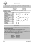
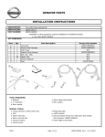
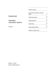
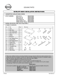
Classification:
Reference:
AT08-001
Date:
NTB08-042
April 3, 2008
2007 MAXIMA; MIL 'ON' W/DTC P0840 OR P0845
APPLIED VEHICLE:
2007 Maxima (A34)
IF YOU CONFIRM
The MIL is ‘ON’ with one of the following DTC stored in the TCM:
•
DTC P0840 – TRANSMISSION FLUID PRESSURE SENSOR A CIRCUIT (SEC
PRESSURE SENSOR)
or
•
DTC P0845 – TRANSMISSION FLUID PRESSURE SENSOR B CIRCUIT (PRI
PRESSURE SENSOR)
NOTE:
• If both P0840 and P0845 are stored, this bulletin does not apply.
•
If other DTCs are combined with P0840 or P0845, resolve the other codes first.
•
If you observe abnormal CVT fluid color or odor, excessive contamination in the
oil pan, and/or you can isolate an unusual noise coming from the transmission,
this TSB does not apply.
•
If needed, refer to ASIST and the Service Manual for further diagnostic
information.
ACTIONS
If DTC is P0845: Replace the Primary Oil Pressure Sensor Assy. with the one listed in the
Parts Information section of this bulletin.
If DTC is P0840: Replace the Secondary Oil Pressure Sensor Assy. with the one listed in
the Parts Information section of this bulletin.
IMPORTANT: The purpose of "ACTIONS" (above) is to give you a quick idea of the work you will
be performing. You MUST closely follow the entire Service Procedure as it contains information that
is essential to successfully completing this repair.
Nissan Bulletins are intended for use by qualified technicians, not 'do-it-yourselfers'. Qualified technicians are
properly trained individuals who have the equipment, tools, safety instruction, and know-how to do a job
properly and safely. NOTE: If you believe that a described condition may apply to a particular vehicle, DO
NOT assume that it does. See your Nissan dealer to determine if this applies to your vehicle.
1/11
PARTS INFORMATION
DESCRIPTION
PART #
Oil Pressure Sensor Assy – Primary
31936-1XA0A
Oil Pressure Sensor Assy – Secondary
Gasket oil pan
31397-1XD00
Nissan CVT Fluid
999MP-NS200P
Seal -lip
31528-1XA01
Bolt -hex
01121-03071
Bolt
31377-1XA04
Bolt-flange hex
081A0-6301A
Seal-O ring, drain plug
31526-1XA01
Bolt
31377-1XD07
QUANTITY
1
1
8 Qts.
2
5
2
4
1
20
CLAIMS INFORMATION
Submit a Primary Failed Part (PP) line claim using the following claims coding:
DESCRIPTION
PFP OP CODE
SYM
DIA
FRT
Replace Primary Oil Pressure
(1)
JX08AA
HD
32
1.2
Sensor Assy.
(1) Reference the Parts Information Table and use the Oil Pressure Assy P/N as the PFP.
OR
DESCRIPTION
PFP OP CODE
SYM
DIA
FRT
(1)
JX09AA
HD
32
1.6
Replace Secondary Oil Pressure
Sensor Assy. (includes R & R
valve body)
(1) Reference the Parts Information Table and use the Oil Pressure Assy P/N as the PFP.
2/11
NTB08-042
SERVICE PROCEDURE
Step A: Remove the oil pan.
CAUTION: Transmissions are very vulnerable to particles (dust, metal, etc.).
• When removing the oil pan or removing a CVT valve body, make sure your work
environment (shop, workbench, etc.), transmission area (sub-frame, oil pan,
harness connector, etc.), and your hands are free of contamination.
• Make sure all parts are clean prior to installing on the vehicle.
• Wait to unpack Service Parts until just before installation.
1. Write down all radio station presets.
Presets
A
B
C
1
2
3
4
5
6
2. Disconnect both battery cables; negative cable first.
3. Remove the CVT dipstick. Raise the vehicle on a hoist.
4. Remove the undercover from below the
front bumper cover (see Figure 1).
Figure 1
5. Remove the transmission pan drain plug and drain the CVT fluid.
6. Loosen and remove the 20 oil pan bolts to remove the oil pan.
7. DECISION:
•
If DTC P0845 is stored, proceed to Step B: Replace Primary Oil Pressure
Sensor Assy.
•
If DTC P0840 is stored, proceed to Step C: Replace Secondary Oil Pressure
Sensor Assy.
3/11
NTB08-042
Step B: Replace Primary Oil Pressure Sensor Assy.
(For P0845 only)
1. Remove the Primary Oil Pressure
Sensor Assy
2. Replace it with the one listed in the
Parts Information section of this
bulletin.
TORQUE: 10.8-14.7 N.m
(1.1-1.5 kg-m, 95.6-130.1 in-lb)
3. Continue to Step D: Closure – page
11.
4/11
Figure 2
NTB08-042
Step C: Replace Secondary Oil Pressure Sensor Assy.
(For P0840 only)
CVT connector
F6
1. Disconnect the CVT harness connector
F6 by turning in the direction shown in
Figure 3.
Figure 3
Manual
Plate
2. Remove the nut and lock nut to remove
the manual plate.
Nut
Lock nut
Figure 4
Collar
3. Remove the collar from the manual
shaft.
Figure 5
5/11
NTB08-042
CVT
Connector
4. Remove the large lock ring holding the
CVT connector to the transmission case
(see Figure 6).
•
Push the transmission side of the
harness down inside the
transmission case to remove it.
Lock ring
Figure 6
• Transmission side of CVT harness
connector and lock ring shown
removed from the transmission case.
Figure 7
5. Disconnect the harness of the Primary oil
pressure sensor assy.
Primary oil pressure sensor assy.
Figure 8
6/11
NTB08-042
6. Remove the bolts attaching the valve body to the transmission (see Figure 9).
•
There are 11 bolts shown and numbered for convenience.
•
There are 3 different length bolts which are identified by:
S-short
M-medium
L-long
3S
8L
9S
7L
6L
5L
4L
2M
10S
1M
11S
Figure 9
Shift link
7. Remove the valve body.
•
Note the position of the Ratio Control
Valve and attached shift link.
Ratio Control Valve
Figure 10
7/11
NTB08-042
8. Make sure you replace the 2 lip seals
shown in Figure 11.
•
Do not reuse the old lip seals.
•
Use petroleum jelly to keep the
new lip seals in place during
reassembly.
Lip seals
Figure 11
9. Carefully remove the valve body
assembly, being careful not to allow the
Ratio Control Valve to fall out.
•
If the Ratio Control Valve does fall
out, check the condition of all
surfaces especially the edges for
damage.
•
Confirm (double check) the
direction of the shift link and the
bottom of the shift link around the
step motor pin (see Figure 12).
Shift link.
Notice the direction
Step motor pin
Figure 12
10. On a clean and lint-free surface, stand
the valve body on-end and hold it as
shown in Figure 13.
Remove the Secondary Oil Pressure
Sensor.
Figure 13
8/11
NTB08-042
11. Replace the Secondary Oil Pressure
Sensor Assy. with the one listed in the
Parts Information section of this bulletin.
TORQUE: 10.8-14.7 N.m
(1.1-1.5 kg-m, 95.6-130.1 in-lb)
Figure 14
Pin
12. Install the valve body and shift link with
the fork end of the shift link around the
pin as shown in Figure 15.
Shift link
Figure 15
Shift link
13. While you are doing Step 12 above, the
lower end of the shift link must stick
through the bottom of the step motor pin
as shown in Figure 16.
Step motor pin
Figure 16
9/11
NTB08-042
14. Install finger tight the 11 valve body bolts removed in Step 6.
IMPORTANT CHECKS:
•
After you install the new valve body, make sure the upper end (forked end) of the
shift link is positioned around the pin. Space is very limited in the work area.
•
Install the CVT dip stick and make sure there is adequate clearance between the
dipstick and the harness.
15. Torque the 11 valve body bolts.
•
Tightening torque: 6.9-8.9 N.m (0.7-0.9 kg-m, 61-78 in-lb).
•
Torque sequence as per Figure 9: 6-7-5-8-4-9-3-10-2-11-1.
16. Re-install the collar on the manual shaft (see step 3, Figure 5).
17. Align the manual plate with the notch in the
manual valve.
NOTE: First, tighten 19 mm nut, then
tighten the 14 mm lock nut with the
specified tightening torque.
•
Manual
plate
Manual
valve
Use a Torque wrench to tighten
both the 14 mm and 19 mm nuts;
same torque specification for both:
TORQUE: 20.6-23.5 N.m
(2.1-2.3 kg-m, 15.1 - 17.3 ft-lb)
Figure 17
18. Reconnect the harness to the primary oil pressure sensor (see step 5, Figure 8).
19. Reinsert the CVT connector with locking ring into the case as shown in step 4, Figure 6.
Make sure that the locating notch is properly engaged.
10/11
NTB08-042
Step D: Closure.
1. Install the oil pan and bolts.
•
Make sure oil pan and magnets are free of contamination particles.
•
Tightening Torque: 5.4 - 7.4 N.m (0.5-0.7 kg-m, 47.8 - 65.5 in-lb).
2. Install the battery cables, negative cable last.
3. Fill and check the CVT fluid level.
4. Reprogram the radio presets.
5. Reset the clock.
6. Initialize the power windows and sunroof as applicable. Reference the Electronic
Service Manual as needed.
7. Using C-III, make sure to erase DTCs from all Systems.
8. Test drive the vehicle and make sure it operates correctly and the Check Engine light is
OFF.
•
If the Check Engine light comes ON; diagnose, perform repairs, and erase DTCs.
•
Diagnosis and repairs beyond the Oil Pressure Sensor Assy. replacement are not
covered by this bulletin.
11/11
NTB08-042