1
GENUINE PARTS
INSTALLATION INSTRUCTIONS
DESCRIPTION:
APPLICATION:
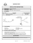
Tow Hitch Wire Harness Kit
Quest (2011)
999T8 NW000
Installation of this accessory requires installation of additional part(s)
● Tow Hitch 999T5 NW010
PART NUMBER:
KIT CONTENTS:
Item
A
B
C
D
E
F
G
H
Qty.
1
1
5
1
2
20
1
1
Part Description
Service Part Number
999T8 NW000S1
999T8 NW000S2
N/A
999T8 NW000S3
N/A
N/A
N/A
24319 89920
Converter
Interior Wire Harness
Foam Tape
Exterior Wire Harness
Bolt, Hex (M5)
Plastic Ties
Owner's Manual
Fuse
G
A
D
C
B
E
H
F
TOOLS REQUIRED:
● Ratchet
● 3" extension
● 8mm socket
● 10mm deep well socket
● Wire cutters
SPECIAL TOOLS:
● Torque Wrench 15 Nm (150 in-lb)
● Drill
● 36mm hole saw
● Nylon removal tool
● Vacuum cleaner
● Center punch
● Measuring tape
● ≥90% alcohol
● Genuine Nissan Tectyl 517 (Bitumen) Wax Sealer
(Part Number: 999MP 9G001P)
● Trailer light circuit tester
DSCA
Page 1 of 15
999T8 MN000 Rev.1 11/11/2010
PRE-INSTALLATION WARNINGS, CAUTIONS, CRITICAL STEPS, and NOTES:
● Installation requires special tool(s).
● Dealer Installation Recommended. Instructions may refer to Service Manual.
WARNING
● When vehicle is raised with a floor jack or hoist, use safety stands to support the vehicle.
CAUTION
● Wear safety glasses when drilling grommet hole and dressing the drilled hole in Step 22.
INSTALLATION OVERVIEW:
GROUND WIRE
COMBI LAMP CONNECTORS
VEHICLE
CONNECTOR
EXTERIOR WIRE
HARNESS 4-PIN
CONNECTORS
INTERIOR WIRE
HARNESS 4-PIN
CONNECTORS
CONVERTER
TRAILER CONNECTOR
(FLAT 4-PIN)
DSCA
Page 2 of 15
999T8 MN000 Rev.1 11/11/2010
INSTALLATION PROCEDURE:
1)
2)
3)
4)
5)
Apply parking brake
Turn ignition switch to "ON" position
Record the customer radio presets and other presets as required
1
1
2
3
Preset
4
5
6
Put shift lever in "P" position.
Turn ignition switch to "OFF" position.
Fig. 1
6)
Disconnect the negative (-) battery terminal.
Fig. 2
7)
Open the rear hatch.
Fig. 3
8)
Use pull straps on the back of the rear seats to fold down
rear seats.
Fig. 4
9)
Fold both storage covers forward.
PULL STRAPS
DSCA
Page 3 of 15
999T8 MN000 Rev.1 11/11/2010
INSTALLATION PROCEDURE:
Fig. 5
10)
Remove storage bin lower section.
Fig. 6
11)
Remove package tray.
Fig. 7
12)
Partially remove rear hatch weather seal from about
as shown
Fig. 8
13)
Remove luggage rear plate.
a) Remove the seven (7) push clips. Place the
reusable clips in a safe place.
b) Remove latch cover. Place the latch cover in a
safe place.
LATCH COVER
CLIPS
CLIPS
Fig. 9
DSCA
c)
Page 4 of 15
Pull up on the luggage rear plate.
999T8 MN000 Rev.1 11/11/2010
INSTALLATION PROCEDURE:
Fig. 10
14)
Remove the two (2) rear trim clips holding the cloth
cover. Place the reusable clips in a safe place.
Fig. 11
15)
Use a small screw driver to press the release on the
driver side cargo net hooks. Place the cargo net hooks
in safe place.
Fig. 12
16)
Use a nylon tool to slightly lift the trim panel.
CLIPS
CAUTION
CLIPS
Fig. 13
● It is important that you position your nylon tool under
clips on the body panel as shown. This will avoid damage to
the clip body panel.
17)
Carefully move panel away from the body to prevent
creasing of the panel. Place the reusable clips in a safe
place.
[Nissan clip part number is: 15-53 10611]
Fig. 14
DSCA
18)
Use a 10mm socket and ratchet to remove the two (2)
retaining bolts from the driver and passenger side
combi lamp assemblies. Place the bolts in a safe place.
Page 5 of 15
999T8 MN000 Rev.1 11/11/2010
INSTALLATION PROCEDURE:
Fig.15
PULL
19)
Remove driver and passenger side combi lamp
assemblies while wiggling and pulling straight back.
FRONT
CAUTION
● Do not pry or pull outward on the combi lamp assembly.
FRONT
Fig. 16
20)
Fig. 17
21)
Disconnect the 4-pin combi lamp connector.
Drill a 36mm hole.
Locate the recessed area on the passenger side of
the vehicle.
a)
b)
c)
Mark the center and center punch the location.
Place a stop 10mm from the end of the saw end of
the hole saw.
d)
Drill the hole using a 36mm hole saw.
36
Fig. 18
WARNING
FRONT
● The hole size and proper dressing of the hole is critical to
prevent exhaust or water intrusion into the interior of the
vehicle.
e)
STOP
Use a file to debur the edge of the hole.
Apply Nissan Wax Sealer P/N 999MP 9G001P (or
equivalent) to the edge of the hole.
CAUTION
● The proper Nissan anti-corrosion spray must be used to
prevent the area around the hole from rusting and/or
corroding.
f)
DSCA
Page 6 of 15
Clean the debris by vacuuming and using a damp
cloth.
999T8 MN000 Rev.1 11/11/2010
INSTALLATION PROCEDURE:
22)
a) Attach the exterior wire harness to the hitch member using nine (9) push clips.
Fig. 19
PUSH CLIPS
b) Install the tow hitch to the vehicle using the tow hitch instructions (P/N 999T5 NW010II).
CAUTION
● Be careful not to damage any of the wire harness connectors.
Fig. 20
23)
After the bumper fascia has been installed, attach the
flat 4-pin connector on the tow hitch using two (2) M5
bolts.
Torque to 3.9 Nm (0.39 Kg-m, 35 in-lb)
8mm BOLTS
Fig. 21
PREVIOUSLY DRILLED
HOLE
PASSANGER
SIDE
DSCA
24)
Route the exterior harness 4-pin connectors through
the previously drilled hole and install the grommet into
the vehicle with the wire harness angled towards the
center of the vehicle.
Note: Pass the grommet all the way through the hole
and then seat the grommet. Make sure the grommet is
completely sealed.
Page 7 of 15
999T8 MN000 Rev.1 11/11/2010
INSTALLATION PROCEDURE:
Fig. 22
Fig. 23
25)
26)
PLASTIC TIE
B
Route the driver side 4-pin connectors to the driver
side combi lamp location as shown.
a)
Remove the shipping tape and uncoil the wire
harness.
b)
Route the wire in the area between the outer body
and inner shell.
Connect the vehicle and tow hitch wire harness
connectors.
a)
Connect the vehicle 4-pin connector (A) to the tow
hitch wire harness connector (B)
b)
Secure the vehicle wire harness connector (A) to
the tow hitch wire connector (B) using a plastic tie.
A
FRONT
Fig. 24
27)
Install the combi lamp assembly on the vehicle.
a) Connector the tow hitch wire harness 4-pin
connector (C) to the combi lamp connector (D).
b)
D
Install the combi lamp assembly on the vehicle
using the two (2) original bolts.
CAUTION
C
● Do not over tighten the bolts.
Fig. 25
Fig. 26
A
B
28)
39)
Route the passenger side 4-pin connectors to the
passenger side combi lamp location as shown.
a)
Remove the shipping tape and uncoil the wire
harness.
b)
Route the wire in the area between the outer body
and inner shell.
Connect the vehicle and tow hitch wire harness
connectors.
a)
Connect the vehicle 4-pin connector (A) to the tow
hitch wire harness connector (B).
b)
Secure the vehicle wire harness connector (A) to
the tow hitch wire connector (B) using a plastic tie.
PLASTIC TIE
DSCA
Page 8 of 15
999T8 MN000 Rev.1 11/11/2010
INSTALLATION PROCEDURE:
Fig. 27
30)
FRONT
Install the combi lamp assembly on the vehicle.
a) Connect the tow hitch wire harness 4-pin
connector (C) to the combi lamp connector (D).
b)
C
D
Install the combi lamp assembly on the vehicle
using the two (2) original bolts.
CAUTION
● Do not over tighten the bolts.
Fig. 28
31)
Secure the passenger side wire harness with two (2)
plastic ties.
Fig. 29
32)
Secure the driver side wire harness with two (2) plastic
ties.
Fig. 30
33)
Clean the surface of the inside driver side rear wheel
well (shaded area) with ≥90% alcohol.
Fig. 31
34)
Wrap foam tape around the vehicle wire harness.
PLASTIC TIES
PLASTIC TIE
3" (80mm)
3" (80mm)
CONVERTER
MOUNTING
LOCATION
FOAM TAPE
DSCA
Page 9 of 15
999T8 MN000 Rev.1 11/11/2010
INSTALLATION PROCEDURE:
Fig. 32
35)
Route the ground wire of the interior tow hitch wire
harness to the mounting stud as shown.
a)
Remove the nut using a 10mm deep socket, 3"
extension and ratchet.
b)
Secure the ground wire eyelet to the stud using
the previously removed nut. Use a 10mm deep
socket, 3" extension and ratchet.
Torque to 6 Nm (0.61 Kg-m, 53 in-lb)
Fig. 33
B
D
36)
A
C
Route the interior wire harness end with the two (2) 4pin connectors from the driver side to the passenger
side, over the jack area and behind the rear body
brace.
a)
Connect the interior 4-pin connector (A) to the
exterior wire harness connector (B).
b)
Connect the interior 4-pin connector (C) to the
exterior wire harness connector (D).
JACK
Fig. 34
37)
CONVERTER
Mount the converter.
a) Connect the interior wire harness 10-pin connector
to the converter.
b)
c)
Remove the tape protector.
Place the converter on the mounting surface as
shown and press firmly into place.
CAUTION
FOAM TAPE
● Do not used excessive force or damage may occur.
Fig. 35
38)
Connect the 1-pin interior wire harness connector to
the vehicle 1-pin connector.
CONVERTER
1-PIN
CONNECTOR
DSCA
Page 10 of 15
999T8 MN000 Rev.1 11/11/2010
INSTALLATION PROCEDURE:
Fig. 36
39)
Secure the wire harnesses.
Clean the area where the foam tapes are to be
applied w/90% alcohol.
a)
FOAM TAPES
b)
Secure the exterior and interior wire harness using
four (4) foam tapes.
c)
Secure the interior wire harness to the vehicle wire
harness using one plastic tie.
PLASTIC TIE
40)
Secure the interior wire harness to the vehicle wire
harness using three (3) plastic ties.
Fig. 38
41)
Remove the fuse cover.
Fig. 39
42)
Insert 20-amp fuse in location as shown.
Fig. 37
PLASTIC TIE
TRAILER LAMP
20-AMP FUSE
DSCA
Page 11 of 15
999T8 MN000 Rev.1 11/11/2010
INSTALLATION CHECK:
Check all torque values. Step 25, Figure 20; Step 35, Figure 32
Verify all wiring is secure and not exposed.
Trim all excess plastic ties flush.
RE-INSTALLATION OF REMOVED PARTS:
Re-install all removed vehicle parts. Refer to the vehicle service manual for more details.
CAUTION
● Use caution when re-installing interior components to avoid damage, scratches, or breaking of mounting clips. Refer
to the vehicle service manual for more information.
1)
2)
3)
4)
5)
6)
7)
8)
9)
10)
11)
DSCA
Install fuse cover.
Put the previously removed clips from the driver side rear trim panel in the clip retainers,
press the driver side rear trim panel back in place.
Install the cargo net hooks.
Install the rear cloth trim using the two (2) clips.
Install the luggage rear plate.
Install the package tray.
Install the storage bin lower section.
Fold both storage covers back to original position.
Return both rear seat backs to the upright position.
Install the rear bumper fascia.
Install the rear hatch weather seal.
Page 12 of 15
999T8 MN000 Rev.1 11/11/2010
ACCESSORY CHECK:
Connect the negative (-) battery terminal and tighten the nut to appropriate torque.
Set ignition switch to "ON" position and the engine stopped.
Confirm tow hitch wire harness converter functions:
Operational Verification:
The following checks are to be performed with the ignition switch in " ON" position and the
engine stopped.
Check
Condition
Turn on headlamps.
Marker and tail lights on both the vehicle
are lit.
Turn on left turn signal.
Left turn lights on both the vehicle and
tester are lit and flashing.
Turn on right turn signal.
Right turn lights on both the vehicle and
tester are lit and flashing.
Apply foot brake.
Stop lights on both the vehicle and tester
are lit.
Turn on left turn signal and apply foot
brake.
Left turn lights on the vehicle and left turn
light on the test are flashing, the right stop
light on the vehicle and tester are lit.
Turn on right turn signal and apply foot
brake.
Right turn lights on the vehicle and right turn
light on the test are flashing, the left stop
light on the vehicle and tester are lit.
Turn on hazard lights switch.
All turn signal lights are flashing on both
the vehicle and tester.
With hazard lights switch on, apply the
foot brake.
Both stop lights on the vehicle are lit, both
turn lights on the vehicle are flashing and
both turn/stop lights on the tester are
flashing.
Turn off the hazard light switch, apply the
foot brake.
Both stop lights on the vehicle and the
turn/stop lights on the tester are lit.
Turn on headlamps.
Marker and tail lights on both the tester and
vehicle are lit.
Apply foot brake.
Stop lights on both the vehicle and tester
are lit.
Turn on left turn signal.
Left turn lights on both the vehicle and
tester are not lit.
DSCA
Page 13 of 15
999T8 MN000 Rev.1 11/11/2010
ACCESSORY CHECK:
Operational Verification: (Cont.)
The following checks are to be performed with the ignition switch in " OFF" position and the
engine stopped.
Check
Condition
Turn on right turn signal.
Right turn lights on both the vehicle and
tester are not lit.
Turn on left turn signal and apply foot
brake.
Both stop lights are lit and not flashing on
both the vehicle and tester.
Turn on right turn signal and apply foot
brake.
Both stop lights are lit and not flashing on
both the vehicle and tester.
With hazard lights switch on, apply the
foot brake.
Both stop lights on the vehicle are lit. Both
turn lights on the vehicle are flashing and
both turn/stop lights on the tester are
flashing.
Turn off the hazard light switch, apply foot
brake.
Both stop lights on the vehicle are lit. Both
turn/stop lights on the tester are lit, but
not flashing.
DSCA
Page 14 of 15
999T8 MN000 Rev.1 11/11/2010
DIAGNOSTIC FLOW CHART
Perform the following Sequence prodcedures if there is any lamp malfunction.
CAUTION
● Check that the headlamp switch is OFF before removing/replacing the bulbs.
DSCA
Page 15 of 15
999T8 MN000 Rev.1 11/11/2010