1
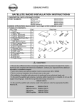
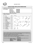
GENUINE PARTS
SATELLITE RADIO INSTALLATION INSTRUCTIONS
1. DESCRIPTION: SATELLITE RADIO SYSTEM
XM tuner kit
2. PART NUMBERS:
SIRIUS tuner kit
XM antenna kit
SIRIUS antenna kit
Sub Harness
3. MODEL APPLICATION: FX35 / FX45 (2003~)
4. TUNER KIT CONTENTS:
No. Parts
Qty
1 Tuner
1
2
2 Black Tape
2
3 Velcro Tape (hook)
2
4 Velcro Tape (loop)
5 Double-Stick Foam Pad
1
6 L Bracket
2
7 M4 Machine Screw
4
4
8 5mm Tapping Screw
9 Ground Cable
1
1
10 6mm Tapping Screw
14
11 Sponge Tape
1
12 Edge Protector
4
13 Clear Tape
1
14 Corrugated Tube
15 Cable Tie
4
2
16 Butyl Gum
4
17 Cable Clamp
999U9-NV003
999U9-NV004
999U9-VQ008
999U9-VQ009
999U9-EP000
Parts View
CAUTION
• This can be a difficult and time consuming installation that may require the skill of the master
technician who is familiar with electronics installation. Contact your regional DTS for additional
information on installation support.
• Tuner unit, antenna, and antenna splitter must be same brand, XM or SIRIUS
• This is a universal installation kit so all parts may not be used.
• Re-installation of satellite radio antenna to be performed by an authorized dealer only.
• In the event the satellite radio antenna or antenna splitter needs to be re-installed, do not use the
original mounting tape. Order the low profile antenna tape remount kit:
999U9-VQ010
• In the event the satellite radio antenna needs to be replaced, order the appropriate Satellite
Antenna Kit.
XM antenna
999U9-VQ014
SIRIUS antenna 999U9-VQ015
XM splitter
999U9-VQ004
SIRIUS splitter 999U9-VQ005
4.22.04
284-9798-20-L0
FX35 / FX45
5. TOOL & MATERIAL REQUIRED:
1.
2.
3.
4.
5.
6.
7.
8.
Phillips screwdriver
Tape measure
Clip remover
Soapy water
Flat file
50/50-alcohol/water solution
Electrical tape
Adhesive tape
9. Masking tape
10. Drill with 4mm (5/32”) bit equipped
with1cm (1/2”) stop
11. Rustproof compound (Bitumen Wax,
999MP-9G001P or equivalent)
12. Plastic Pry bar (P/N J-46534 or
equivalent)
13. Socket wrench with 10mm, 12mm sockets
!l#sti' )r+ b#r
6. INSTALLATION OUTLINE:
7. VEHICLE PREPARATION:
(1) Remove all items from cargo area, including cargo cover.
(2) Record the customer radio presets.
1
2
3
AM
AM2
FM1
FM2
FM3
ESN number located on tuner box:
(3)
(4)
(5)
(6)
(7)
-.//.0-
4
5
6
7
Apply parking brake.
Make sure that the shift lever is engaged in the "P" position.
Open hatch
Open the hood of the vehicle.
Disconnect the battery negative terminal to prevent short circuits during installation.
/123
/4-567645/0580
FX35 / FX45
8. ANTENNA INSTALLATION:
c
Fig. 1
(1) Remove the two (2) 12mm screws (c) that secure
the cargo area carpeted floor trim straps and
remove the floor trim piece (a) and small drivers
side corner trim piece (b). Fig. 1
(2) Fold rear seats forward.
b
a
(3) Unscrew spare tire clamp (d). Lift and move
subwoofer box (e), to sit on right rear seat back.
Fig. 2
d
e
(4) Lift and remove the spare tire (f). Fig. 2
f
Fig. 2
Fig. 3
(5) Remove the cargo area entrance trim piece.
Fig. 3
NOTE
This piece is held in place by means of six (6)
metal clips. The position of these clips is called
out by the squares on Fig. 4
Fig. 4
screws
(6) Remove three 10mm screws that secure cargo
flap to the spare tire well. Remove the flap and set
aside. Fig. 5
(7) Remove the jack.
Fig. 5
!"##"$!
%&'%
#(!-*+*(-#$-,$
cap
screws
FX35 / FX45
Remove
the
cargo
tie
down
bracket,
10mm
screw
(8)
and bolt cap that secure the spare tire well in
place. Fig. 6
(9) Lift and rotate the driver side spare tire well up and
out of the cargo area.
Fig. 6
(10) Remove weather-strip from the entire left side of
the cargo opening, all the way to the bottom.
(11) Release the driver's side of the roof rear garnish
assembly. Fig. 6b
CAUTION
Do not remove entire roof rear garnish assembly.
clips
Fig. 6b
(12) Remove the finisher from the driver side cargo
hatch hinge.
(13) If roof rack is present remove finisher caps from
each end of the driver's side rail. Use plastic pry
bar to release this piece. Pry at point 1 then move
to point 2 but DO NOT pry the rear portion of this
piece. Fig. 7
Fig. 7
NOTE
Each of these pieces are held in position by four
(4) small locking tabs. The tab locations are
illustrated by the triangles in Fig. 8
1
Do NOT
pry here
2
CAUTION
'o)*ing
Do NOT use PGF stick or flat blade driver to
remove finisher caps. To avoid damaging the
locking tabs use a plastic pry bar to pry outward
then up to remove the cap. Use extreme care!
'o)*ing
!ig$ &
CAUTION
Do NOT break off locking pin on finisher cap
during removal.
roof side molding
(14) If roof rail is present remove the four (4) 10mm
nuts securing the rail to the vehicle.
!ig$ ,
4$22$04
(15) Lift rail straight up to remove from mounting bolts.
(16) Using PGF stick or plastic pry bar remove roof
side molding. This piece is held in place with six
(6) clips. The clip locations are illustrated by
circles in Fig. 9. If present, remove PGF
protective film from rear of the roof where antenna
is to be mounted.
4783
2&4-,;,&-20-'0
FX35 / FX45
(17) Place the antenna on the roof in the approximate
position it will be mounted, see Fig. 10. Align the
stiff portion of the tail to the edge of the rain gutter
with the flexible portion of the tail extended into the
gutter. The flexible portion of the tail will be aimed
downwards and secured between the gutter edge
and the gutter finisher.
Fig. 10
(18) Proper alignment of the antenna tail is achieved by
adjusting the position of the antenna so the small
vertical portion of the antenna is contacting the
gutter edge of the roof while maintaining the
smallest visible gap between the antenna tail and
edge of the roof line.
Front of vehicle
Fig. 11
(19) Place a small piece of masking tape, perpendicular
to rain gutter, a distance of 212mm (+2mm, -0mm)
from the rear edge of the roof. Fig. 11
172mm
masking tape
212mm
(20) Place second piece of masking tape 172mm
(+2mm, -0mm) from rear edge of roof to portion of
roof closest to the widest portion of the antenna
head. Fig. 11
CAUTION
Driver side rain gutter
In case of ambient temperatures below 20 degrees
C (70 degrees F), it is required to warm the tape
and mounting surface with a heater to a minimum
of 20 degrees C (70 degrees F).
(21) Use these two pieces of tape to position antenna
by aligning the rear edge of the tail to the front edge
of the tape. Fig. 11 Double check to ensure
antenna is perpendicular to rain gutter.
!"##"$!
%&'(
#)!*+,+)*#$*-$
FX35 / FX45
(22) Unwrap the antenna cable.
CAUTION
! Do not let the antenna cable rest on floor; it may
be stepped on and damaged.
! Do not kink the antenna cable.
(23) Bend the antenna wire to a right angle, directed
towards the rear of the vehicle, at the point where
they exit the flexible portion of the tail.
Fig. 12
(24) Carefully lift the antenna from the roof and clean the
area where the antenna is to be mounted with a
50/50 alcohol/water solution. Put antenna back on
roof.
CAUTION
Do not touch or contaminate the cleaned roof or
adhesive tape on the antenna to prevent reduction
of adhesive strength.
(25) Adjust the position of antenna such that the
antenna tail and roof have maximum contact surface
with minimum gap at edge of roofline. Fig. 12
Antenna cable
Fig. 13
(26) Peel tape protector from the antenna tail and lay
down tail. Fig. 12
CAUTION
Make sure the antenna cable remains vertical under
antenna tail flap. Fig. 13
4$%%$&4
'()*
%+4,-7-+,%&,/&
FX35 / FX45
(27) Apply pressure along the length of the antenna tail
to ensure proper adhesion.
F"#$ 14
(28) Apply 20 lbs. of downward force for 20 seconds
while rocking hand back and forth across top of
antenna to assure proper adhesion. Fig. 14
CAUTION
During antenna mounting process, make sure
rubber dust seal "flares" outward while downward
force is applied.
(29) Masking tape used for antenna alignment can
carefully be removed from roof.
CAUTION
F"#$ 1)
(
Make sure the antenna cable remains vertical
and centered under antenna tail flap in order to
have maximum wetout surface on both sides of
tape.
(
Keep vehicle inside at least one hour after
applying adhesive tape.
(
Avoid works imposing pressure on the
adhered area including car wash within 48 hours.
-a/,
*"r,
(30) Use masking tape to secure the wire into the rain
gutter in one (1) place. Fig. 15
(31) Route the antenna cable in rain gutter then under
the plastic trim cover towards the existing notch
area located in the center of the cargo opening.
Fig. 16
notch
Fig. 16
antenna cable routing
(32) Re-install roof side molding.
CAUTION
Ensure grommets on side molding align with clips
on roof during re-installation of roof side molding.
4$22$04
2314
254-9295-20-80
FX35 / FX45
see Fig &0
1 &2
clear tape
Fig. &'
Cargo area side
(33) Reinstall roof rail, roof rail cap, and cross bar end
covers. Apply torque: M6 screws 5.0 to 5.5 N-m
(44.3 to 48.7 in-lbs) and M8 screws 6.0 to 6.5 Nm (53.1 to 57.5 in-lbs).
(34) Clean the gutter and the underside of it with 50/50
alcohol/water solution.
(35) Cut one (1) piece of clear tape in half then secure
the antenna wire in front corner of gutter by placing
tape over the wire then wrap excess tape over the
top edge of the gutter. First piece of tape aligns
with edge of hatch hinge. Second piece is
centered between first piece and existing notch at
center of vehicle. Fig. 17
NOTE
Roof side
Fig. 18
The following steps 36 to 42 are critical to water
leak, therefore must be followed strictly.
(36) Place the edge protector over the existing notch.
(37) Use alcohol wipe included in kit to clean
surrounding area before application of clear tape.
(38) Route the antenna cable over the edge protector by
laying cable into the channel in the rubber.
CAUTION
3 Make sure the antenna cable is seated in
channel on both sides of the edge protector.
Fig. 19
3 In order to stop water from entering the trunk
through the clear tape, the clear tape must have
complete (100%) wet out 5 - 10mm (1/4" - 3/8")
on all three sides of peripheral boundary and no
wrinkles. Fig. 18
3 Ensure the antenna cable is entering the clear
tape at the radius corner.
(39) Position the clear tape above the notch without
peeling off the liner to estimate the correct position
for the small amount of butyl gum.
(40) Before applying the clear tape, apply a small
amount of butyl gum to the bottom side of the
antenna cable to hold it at the radius corner where
the cable will enter the clear tape.
4.22.04
07&3
204-2'20-20-L0
FX35 / FX45
!"#$ &(
)p+,#e tape
!"#$ &'
(41) Do not peel off the entire clear tape protector. Pull
the clear tape protector back 10mm (3/8"). Then
apply 10mm clear tape to the horizontal flat
surface of the gutter. Then slowly massage the
clear tape with a PGF stick until you have reached
the corners. Make sure that the tape does not
wrinkle. Apply the same technique to the vertical
surface. Then fold the tape over and apply the
technique once more. This should leave a smooth
surface on all three sides. Fig.18 & 19
(42) Apply butyl gun at both ends of the clear tape.
The butyl gum should fit into both corners to cover
the antenna cable and opposite end of clear tape.
Fig. 18
CAUTION
Butyl gum must be placed across the cable for
good water seal.
(43) Loop the antenna cable back towards driver's side
and secure with four (4) pieces of sponge tape.
Fig. 20
(44) Push roof rear garnish assembly back into
position.
!"#$ &&
(45) Re-install cargo hatch hinge finisher.
(46) Remove protective backing from sponge tape,
position the antenna wire along centerline of
sponge tape and fold the foam tape length wise
about the antenna wire. Fig. 21
(47) Tuck the folded foam tape and wire between the
trim panel and the weather-strip gutter. This
procedure should be done at four (4) positions
along the trim piece. Fig. 22 & 23
0$&&$(0
12'3
&80516185&(57(
FX35 / FX45
(48) Route the antenna cable to cargo area along
existing harness. Fasten wires to harness with five
(5) pieces of sponge tape. Fig. 24
(49) Place clear tape over edge of metal bracket on
drivers side of spare tire storage area where
antenna cable will cross against. Fig. 25
t405 p*i+t(
!i#$ 23
(p*+#e tape
!i#$ 2'
(p*+#e tape
(50) Route antenna cable cross against clear tape, Fig.
25, towards tuner location (see page 2).
0lear tape
!i#$ 2/
(51) Cut a piece of clear tape in half and place each half
over the two (2) vertical metal brackets located
directly above the tuner location, on the underside
of the metal structure. Fig. 26
!i#$ 26
0lear tape
9. N-BUS CABLE INSTALLATION
t8e *pe+i+#
!i#$ 26
9-B4( <4mper
8ar+e((
(1) Remove tape to release N-Bus harness connector.
(2) Connect end of short N-Bus jumper harness to the
connector of the factory prewired N-bus harness.
(3) Route short N-Bus harness through the opening
then back towards the center area of the rear seat.
0a7le tie(
'$22$0'
(4) Secure this harness along the top of the existing
vehicle harness with two (2) cable ties. Fig. 27
10A13
2B'-C6CB-20-D0
FX35 / FX45
10. TUNER INSTALLATION AND WIRE CONNECTION
400 x 30 x 3
Fig. 28
(1) Cut three (3) 100mm by 30mm spacers and six (6)
50mm by 20mm spacers from the double stick
spacer (item # 5 in kit contents).
(2) Remove the protective backing from the spacers.
Stack three of the 50mm by 20mm spacers
together to form a triple thickness spacer. Repeat
this process with the remaining 50mm by 20mm
pieces and then the 100mm by 30mm pieces.
50 x 20 x 3
(3) Clean metal surface behind and under the center
section of the rear seat with 50/50 alcohol/water
solution where tuner will be attached.
ground
cable
Fig. 29
(4) Position these triple thick spacers on the metal
surface behind and under the center section of the
rear seat. Fig. 28
ground
screw
CAUTION
Do not put spacers on top of bolt heads.
(5) Attach the ground cable to the tuner. Fig. 29
Fig. 30
Fig. 34
(6) Attach the other end of the ground cable to the
metal surface behind the drivers side rear
passenger seat by loosening the existing screw,
sliding the terminal under it, and tightening it
securely. Fig. 30
(7) Clean back side of tuner surface, where it is to be
mounted to stacked spacers, with alcohol/water
solution.
(8) Remove the protective backing from the spacers
that are positioned on the metal center section and
affix the tuner in position on them as low as
possible. Fig. 31
(9) Insert antenna splitter cable connectors into
corresponding tuner terminals.
4.22.04
44;43
284-9=98-20-L0
FX35 / FX45
(10) Clean the metal frame with 50/50 alcohol/water
solution where the splitter is to be attached. Fig.
32
0p1#tter
"#$% '3
Excess antenna cable
(11) Peel off the tape protector from the splitter. Place
the splitter on the metal frame with dual leads
facing the passenger side of the vehicle. Secure
in position by applying downward force with hand
pressure. Fig. 32
(12) Leaving enough length for the splitter connection,
neatly coil excess antenna cable to create a loop
100mm (4") in diameter.
CAUTION
! Do not kink the antenna cable.
! Do not change diameter of the antenna loop.
"#$% ''
(13) Connect the antenna cable connector to the
antenna splitter.
(14) Secure antenna loop to the metal surface behind
the drivers side rear passenger seat with sponge
tape. Fig. 33
(15) Connect N-Bus cable connector to the
corresponding tuner terminal.
"#$% '/
(p*+$e tape
(16) Secure antenna cables to N-Bus harness with
sponge tape.
(17) Attach N-Bus harness to the metal surface behind
the drivers side rear passenger seat with two (2)
pieces of sponge tape. Fig. 34
/%33%4/
5365'
37/89:978348;4
FX35 / FX45
11. OPERATION CHECK
(1) Connect the battery negative terminal.
(2) Turn vehicle ignition switch to the "ACC" position.
(3) Turn radio on then select satellite radio mode. Acquiring (Sirius) or loading (XM) will display
for a while. If not, move vehicle to outside and try again.
(4) Tune to preview channel (XM: channel "1" / SIRIUS: channel "184") to make sure receiving
preview channel correctly.
(5) Confirm proper audio operation. (AM / FM / TAPE / CD)
12. REINSTALLATION OF REMOVED PARTS
(1) Re-install all removed vehicle parts referring to the service manual for the vehicle.
(2) Clean interior of vehicle.
CAUTION
If roof rack cross bars are present the rear cross bar must be installed in the middle position.
Failure to install cross bar in this position could lead to poor satellite radio performance due to
satellite antenna interference.
13. FINAL INSPECTION
(1) Inspect the vehicle interior and exterior for damage.
(2) Confirm proper operation of vehicle systems including moonroof if equipped.
(3) Reset radio presets to the recorded settings.
(4) If equipped reset the moonroof per service manual requirement.
4.22.04
13/13
284-9798-20-L0