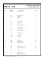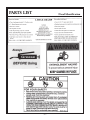
1
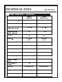
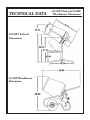
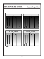
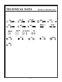
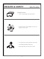
OPERATOR & SERVICE MANUAL MODEL: 25CMP Wheelbarrow & 25CMPT Pedestal CHAMPION® PLASTIC CONCRETE MIXER A 100% employee-owned American manufacturer REVISION: C 01/2004 PN 56517 Table of Contents 25CMPT/25CMP FOREWORD ...................................................................................................................... 4 LIMITED WARRANTY ................................................................................................... 5 TECHNICAL DATA ......................................................................................................... 6-9 Specifications ................................................................................................................ 6 25CMPT Pedestal Dimensions ..................................................................................... 7 25CMP Wheelbarrow Dimensions ............................................................................... 7 Imperial Torque Chart ................................................................................................... 8 Hardware Identification ................................................................................................ 9 HEALTH & SAFETY ....................................................................................................... 10-14 OPERATION ...................................................................................................................... 15-16 Before Starting ............................................................................................................... 15 Hardware ........................................................................................................................ 15 To Start/To Stop the Electric Motor ............................................................................. 15 Operation ........................................................................................................................ 15 Capacities ....................................................................................................................... 15 How to Mix Concrete/How to Mix Sand & Gravel .................................................... 16 Maintenance and Lubrication ....................................................................................... 16 MAINTENANCE ............................................................................................................... 17-23 Pedestal Model Assembly ............................................................................................. 17 Grease ............................................................................................................................. 17 Lubrication ..................................................................................................................... 17 25CMP Wheel & Frame Assembly .............................................................................. 18 25CMP--Electric Motor Assembly ............................................................................... 19 25CMP--Pulley & Ring Gear Assembly ...................................................................... 20 25CMP--Drum & Ring Gear Assembly ....................................................................... 21 25CMP--Drum Installation Assembly .......................................................................... 22 25CMP--Wheelbarrow Final Assembly ....................................................................... 23 EXPLODED DIAGRAM AND PARTS LIST ............................................................... 24-29 25CMPT Frame, Drum, & Motor Assembly ............................................................... 24-27 25CMP Frame, Drum, & Motor Assembly .................................................................. 28-29 Decal Identification ....................................................................................................... 30-31 CALIFORNIA PROPOSITION 65 WARNING ........................................................... IBC -3- User Information Foreword These instructions include: Safety regulations Operating instructions Maintenance instructions These instructions have been prepared for operation on the construction site and for the maintenance engineer. These instructions are intended to simplify operation of the machine and to avoid malfunctions through improper operation. 1. Machine S/N: _______________________________ 2. 3. VIN: ______________________________________ 4. Purchase Date: ______________________________ 5. Dealer/Distributor Information: Name: _____________________________________ Address: ___________________________________ __________________________________________ Always keep these instructions at the place of use of the machine. Phone #: ___________________________________ Only operate the machine as instructed and follow these instructions. Stone Construction Equipment, Inc. is not liable for the function of the machine when used in an improper manner or for other than the intended purpose. Engine Type: _______________________________ Engine S/N: ________________________________ Observing the maintenance instructions will increase the reliability and service life of the machine when used on the construction site and reduce repair costs and downtimes. Observe the safety regulations as well as the guidelines of the civil engineering trade association. Observe the safety rules for operation and the pertinent regulations for the prevention of accidents. Machine Type: ______________________________ Fax #: _____________________________________ 6. Battery Manufacturer: ______________________________ Battery Type: _______________________________ Battery S/N: ________________________________ Location of above information: Operating errors, improper maintenance and the use of incorrect operating materials are not covered by the warranty. The above information does not extend the warranty and liability conditions of business of Stone Construction Equipment, Inc. 1. Information on S/N tag. 2. Information on engine tag. 3. Information on S/N tag - if applicable. 4. Date you purchased machine. 5. Dealer machine was purchased from. 6. Information on battery and battery warranty card. Stone Construction Equipment, Inc. P.O. Box 150, Honeoye, New York 14471 Phone: (800) 888-9926 Fax: (585) 229-2363 -4- L i m i t e d W a r r a n t y The Manufacturer warrants that products manufactured shall be free from defects in material and workmanship that develop under normal use for a period of 90 days for concrete vibrators and electric pumps, one year for Rhino®, Bulldog®, WolfPac Rollers, trowels, Stompers®, saws, forward plates, engine powered pumps, Lift Jockey, Mortar Buggy and 6 months for all other products from the date of shipment. The foregoing shall be the exclusive remedy of the buyer and the exclusive liability of the Manufacturer. Our warranty excludes normal replaceable wear items, i.e. gaskets, wear plates, seals, Orings, V-belts, drive chains, clutches, etc. Any equipment, part or product which is furnished by the Manufacturer but manufactured by another, bears only the warranty given by such other manufacturer. (The Manufacturer extends the warranty period to “Lifetime” for the drum bearings and seals for the mortar mixers, and agrees to furnish, free of charge, the bearings and seals only upon receipt of the defective parts. The warranty is two years for eccentric bearings on the forward plate compactors, mortar and plaster mixer drums, trowel gearboxes, three years on the Bulldog trench roller microprocessor (ECIB) and five years on the Bulldog trench roller eccentric bearings.) A Warranty Evaluation Form must accompany all defective parts. Warranty is voided by product abuse, alterations, and use of equipment in applications for which it was not intended, use of non-manufacturer parts, or failure to follow documented service instructions. The foregoing warranty is exclusive of all other warranties whether written or oral, expressed or implied. No warranty of merchantability or fitness for a particular purpose shall apply. The agents, dealer and employees of Manufacturer are not authorized to make modification to this warranty, or additional warranties binding on Manufacturer. Therefore, additional statements, whether oral or written, do not constitute warranty and should not be relied upon. The Manufacturer’s sole responsibility for any breach of the foregoing provision of this contract, with respect to any product or part not conforming to the Warranty or the description herein contained, is at its option (a) to repair, replace or refund such product or parts upon the prepaid return thereof to location designated specifically by the Manufacturer. Product returns not shipped prepaid or on an economical transportation basis will be refused (b) as an alternative to the foregoing modes of settlement - the Manufacturer’s dealer to repair defective units with reimbursement for expenses, except labor, and be reviewed with the Manufacturer prior to repair. A Warranty Evaluation Form must accompany all warranty claims. Except as set forth hereinabove and without limitation of the above, there are no warranties or other affirmations which extends beyond the description of the products and the fact hereof, or as to operational efficiency, product reliability or maintainability or compatibility with products furnished by others. In no event whether as a result of breach of contract or warranty or alleged negligence, shall the Manufacturer be liable for special or consequential damages including but not limited to: Loss of profits or revenues, loss of use of the product or any associated product, cost of capital, cost of substitute products, facilities or services or claims of customers. No claim will be allowed for products lost or damaged in transit. Such claims should be filed with the carrier within fifteen days. Effective January 2004. Stone Construction Equipment, Inc. 8662 Main Street, P. O. Box 150 Honeoye, NY 14471-0150 Phone: 1-800-888-9926 1-585-229-5141 Fax: 1-585-229-2363 P/N 51018 G-7524 01/2004 -5www.stone-equip.com e-mail: [email protected] TECHNICAL DATA Specifications 25CMPT/25CMP Mixer – Specifications 25CMPT (Pedestal) 25CMP (Wheelbarrow) %DWFK&DSDFLW\EDJV óEDJ óEDJ %DWFK&DSDFLW\7RWDO FXIW FXIW FXIW FXIW (OHFWULF (OHFWULF DPS DPS 6LQJOH 6LQJOH 2SHUDWLQJ:HLJKWOEV 9ROXPHRIHPSW\GUXP &DSDFLW\&RQFUHWH 9ROXPH7RWDOZHW /[:[+ 0RWRU+3 0RWRU530 9ROWDJH )UHTXHQF\+] 3KDVH 'UXP530 9%HOW/6HFWLRQ /HQJWK 'UXP'LDPHWHU[ 2SHQLQJ 'UXP7\SH 6WUXFWXUH 3RUWDELOLW\ 3RO\HWK\OHQH'UXP 3RO\HWK\OHQH'UXP 3HGHVWDO :KHHOEDUURZ 6HSDUDWHVLQWRSLHFHV -6- :KHHOHG)UDPH TECHNICAL DATA 25CMPT Pedestal Dimensions 25CMP Wheelbarrow Dimensions -7- 25CMPT Pedestal/25CMP Wheelbarrow Dimensions TECHNICAL DATA Imperial Torque Chart 6$(*5$'( 6$(*5$'( &RDUVH7KUHDG=LQF3ODWHG &RDUVH7KUHDG=LQF3ODWHG 6,=( 72548( 6,=( 72548( IWOEV 1P IWOEV 1P 6$(*5$'( 6$(*5$'( )LQH7KUHDG=LQF3ODWHG )LQH7KUHDG=LQF3ODWHG 6,=( 72548( 6,=( IWOEV 1P 72548( IWOEV 1P WFKUWBLGRF -8- TECHNICAL DATA -9- Hardware Identification HEALTH & SAFETY Before using this equipment, study this entire manual to become familiar with its operation. Do not allow untrained or unauthorized personnel, especially children, to operate this equipment. Use only factory authorized parts for service. Safety Precautions When warning decals are destroyed or missing, contact the Manufacturer immediately at 1-800-888-9926 for replacement. For the safety of yourself and others, it is imperative that the following rules are observed. Failure to do so may result in serious injury or death. FOLLOW SAFETY INSTRUCTIONS Carefully read all safety messages and decals in this manual and on your machine safety signs. Keep decals in good condition. Replace missing or damaged decals. Be sure new equipment components and repair parts include the current safety signs. Replacement safety signs and decals are available through your dealer. Learn how to operate the machine and how to use controls properly. Do not let anyone operate without instruction. Keep your machine in proper working condition. Unauthorized modifications to the machine may impair the function and/or safety and affect machine life. If you do not understand any part of this manual and need assistance, contact your dealer. This notation appears before warnings in the text. It means that the step which follows must be carried out to avoid the possibility of personal injury or death. These warnings are intended to help the technician avoid any potential hazards encountered in the normal service procedures. We strongly recommend that the reader takes advantage of the information provided to prevent personal injury or injury to others. UNDERSTAND SIGNAL WORDS A signal word DANGER, WARNING, or CAUTION is used with the safety-alert symbol. DANGER identifies the most serious hazards. DANGER or WARNING safety signs are located near specific hazards. General precautions are listed on CAUTION safety signs. CAUTION also calls attention to safety messages in this manual. - 10 - HEALTH & SAFETY Safety Precautions USE COMMON SENSE WHEN HANDLING FUELS Transport and handle fuel only when contained in approved safety container. Do not smoke when refueling or during any other fuel handling operation. Do not refuel while the engine is running or while it is still hot. If fuel is spilled during refueling, wipe it off from the engine immediately and discard the rag in a safe place. Do not operate the equipment if fuel or oil leaks exist - repair immediately. Never operate this equipment in an explosive atmosphere. Always use the proper size grounded extension cord, conforming to the National Electric Code and Local Ordinances. Inspect all extensions and electrical cords for cuts, frayed wire and broken connectors before use. Do not use cords if not in good condition. Do not route extension cords through standing water. Do not operate the mixer in standing water. When cleaning the mixer, never spray water on the electric motor. HOT SURFACES WARNING Avoid contact with hot exhaust systems and engines. Allow all components in the engine compartment to cool before performing any service work. Never leave mixer unattended while running. Mix only concrete. - 11 - HEALTH & SAFETY Safety Precautions Never perform any work on the mixer while it is running. Before working on the mixer, stop the engine and disconnect the spark plug wire(s) to prevent accidental starting. On electric models, disconnect the electric cord at the mixer. Keep cowl closed and latched during the operation, close and latch cowl immediately after starting. Keep hands, clothing and jewelry away from all moving parts. Keep all guards in place, including drum guards. Never place your hands or any solid object into the drum while the mixer is in operation. WEAR PROTECTIVE CLOTHING Wear close fitting clothing and safety equipment appropriate to the job. Prolonged exposure to loud noise can cause impairment or loss of hearing. Wear a suitable hearing protective device such as earmuffs or earplugs to protect against objectionable or uncomfortable loud noises. Operating equipment safely requires the full attention of the operator. Do not wear radio or music headphones while operating machine. PREPARE FOR EMERGENCIES Be prepared if a fire starts. Keep a first aid kit and fire extinguisher handy. Keep emergency numbers for doctors, ambulance service, hospital, and fire department near your telephone. - 12 - HEALTH & SAFETY Safety Precautions Warning-Eye Protection • Always wear splash goggles when operating mixer. Starting fluid (ether) is highly flammable, do not use or an explosion or fire may result. Never operate unit in a poorly ventilated or enclosed area. Avoid prolonged breathing of exhaust gases. Engine exhaust fumes can cause sickness or death. - 13 - HEALTH & SAFETY Safety Precautions PRACTICE SAFE MAINTENANCE Understand service procedure before doing work. Keep area clean and dry. Never lubricate, service or adjust machine while it is moving. Keep hands, feet, and clothing from power-driven parts. Disengage all power and operate controls to relieve pressure. Lower equipment to the ground. Stop the engine. Remove the key. Allow machine to cool. Securely support any machine elements that must be raised for service work. Keep all parts in good condition and properly installed. Repair damage immediately. Replace worn or broken parts. Remove any buildup of grease, oil, or debris. Disconnect battery ground cable (-) before making adjustments on electrical systems or welding on machine. DISPOSE OF WASTE PROPERLY Improperly disposing of waste can threaten the environment and ecology. Potentially harmful waste used with equipment include such items as oil, fuel, coolant, brake fluid, filters, and batteries. Use leakproof containers when draining fluids. Do not use food or beverage containers that may mislead someone into drinking from them. Do not pour waste onto the ground, down a drain, or into any water source. Air conditioning refrigerants escaping into the air can damage the Earths atmosphere. Government regulations may require a certified air conditioning service center to recover and recycle used air conditioning refrigerants. Inquire on the proper way to recycle or dispose of waste from your local environmental or recycling center. SAFETY DECALS - FOR THE SAFETY OF YOURSELF AND OTHERS REPLACE ANY DAMAGED OR MISSING SAFETY DECALS. Decal Safety Instructions (CMPT) PN 55046 Decal Safety Instructions (25CMP) PN 55491 Decal Instruction Mix (25CMP) PN 55490 Decal Grease PN 55492 Decal Warning PN 55493 - 14 - Before Starting/Hardware/Start & Stop Electric Motor OPERATION BEFORE STARTING OPERATION The 25CMP mixer is shipped completely assembled and ready for operation. Start the motor as instructed. With drum operating between 25-30 RPM, the mixer is now ready for the addition of the concrete mix. For best results proceed as follows: 1. Pour the required amount of water into drum. WARNING TO PREVENT ANY ACCIDENTAL STARTING, MAKE SURE THE ELECTRIC CORD IS DISCONNECTED 2. Add the required amount of gravel. 3. Add the required amount of cement. 4. Add the required amount of sand. HARDWARE Check all hardware on mixer before starting. Consult the TORQUE CHART section of this manual and tighten any loose hardware accordingly. By adding the water and gravel first the drum will be kept clean and a good tumbling action will be maintained when cement and sand are added. Discharge the mixer and immediately pour in the required water for the next batch. TO START THE ELECTRIC MOTOR CAPACITIES Use the proper size (3) wire (grounded) extension cord, conforming to the National Electric Code and Local Ordinances. DO NOT use (2) wire extension cords. Check any extension cord which you plan on using carefully for broken connectors, bare wires, or damaged insulation. DO NOT use any cord found to be in poor condition. Make sure the extension cord is not routed through standing water and that all connections are tight. Use the shortest extension cord possible. Plug into any 115 single phase, 60-cycle, fused outlet. Turn motor on. Check belt tension and tracking . * Maximum batch size depends on mix and type of aggregate used. TO STOP THE ELECTRIC MOTOR Turn motor off. Disconnect the power cord. - 15 - Total Drum Volume 3.5 cu. ft. Max Batch Size* 2 cu. ft. OPERATION How to Mix Concrete/How to Mix Sand & Gravel/Maintenance & Lubrication How to Mix Concrete WARNING 1. You will need approximately 2-1/2 gallons of water 2. 2-80 lb. bags of pre-mix concrete 3. Start mixer in motion 4. Put in 2-gallons of water 5. Add 1-80 lb. bag of pre-mix concrete NEVER POUR OR SPRAY WATER ON THE MOTOR. NEVER PLACE HANDS OR ANY OBJECT INTO THE DRUM WHILE THE MOTOR IS RUNNING. Note: Mixture will be very sloppy 6. Slowly add second bag of concrete 7. Add ½ gallon of water slowly to obtain desired thickness ALWAYS DISCONNECT THE ELECTRIC CORD WHEN CLEANING INSIDE THE DRUM. How to Mix Sand and Gravel MAINTENANCE and LUBRICATION 1. Use an 8-1/2 x 12-inch square point shovel 2. Portland cement, gravel or round stone and masonry sand 3. Start mixer in motion 4. Put in 2 gallons of water 5. Add 6 shovels full of gravel or round stone 6. Add 2 shovels full of Portland Cement 7. Slowly add 4 shovels full masonry sand To get long and trouble-free service from this mixer, it is essential that you perform periodic maintenance. Adjust belt as required by loosening the (4) motor mount bolts and moving motor as necessary. Retighten these bolts after adjustment. The belt should deflect approximately 1/4 inch at the halfway point when 5-10 lbs of pressure is applied. Note: Water will vary according to moisture content of sand and gravel Adjust pinion/gear mesh as required by loosening the two (2) pinion jackshaft bolts and moving jackshaft as necessary. Retighten these bolts after adjustment. Grease after each use through the (2) fittings provided. Use any Grade #1 lithium based grease. DO NOT grease or oil the gear. This will attract sand and cause excessive wear. - 16 - MAINTENANCE 25CMPT Pedestal Assembly PEDESTAL MODEL ASSEMBLY Place Thrust Washer (25) onto Drum Shaft (15) and lightly grease the shaft. Using two people, carefully slide the Drum assembly with shaft into the tube located centrally on the Frame (4). Check to see that the Jackshaft Gear (10) is properly meshing with the Drum Main Gear (14). Place locking Collar (17) onto Shaft (15) and tighten setscrew. WARNING WHENEVER ASSEMBLING, LUBRICATING OR ADJUSTING ANY PART OF THE MIXER, DISCONNECT THE POWER PLUG. Grease the Fitting (24) on the Drum Shaft tube until grease appears near the locking Collar (17) and the Thrust Washer (30). To attach motor (6) to frame assembly (4), line up motor to match the four holes on the side motor mount. Attach the V-belt (8) to the motor pulley (7). Using the four 5/16 x ¾ in Hex Flange Screws (31) and four 5/16 Hex Flange Lock Nuts (32), secure the motor in place. The V-belt should be tightened until the belt deflects approximately ¼ in when 5-10 pounds of force is applied centrally between the pulleys. Assemble base legs (1 and 2). Assemble Yoke (3) to assembled base and pin (29). Using two people, lift and place Frame Assembly (4) onto Yoke (3) pivot pins and insert pins (26). Slide dump handle Grip (19) over the end of the Dump Handle (18) and insert the Handle in the Frame Assembly (4). Check the clearance of Gear Guard (21) and the Drum (5) to make sure there is no contact between the rotating Drum and the Guard. LUBRICATION Any grease fittings (Item 24) require an application of any type EP grease after each use. Apply grease until grease begins to come out of the bushings. Lubricate before each use of the mixer. GREASE Using a grease gun, apply grease to the Fitting (24) on the Jackshaft Tube if not already greased at factory. Plug in the Power Cord. Let the motor run for about 5 to 8 minutes, then turn off motor. This will break-in the jackshaft bushings. WARNING KEEP HANDS AND CLOTHING AWAY FROM MOVING JACKSHAFT AND GEAR. - 17 - 25CMP Wheelbarrow-Wheel & Frame Assembly MAINTENANCE - 18 - 25CMP Wheelbarrow-Electric Motor Assembly MAINTENANCE 35 - 19 - 25CMP Wheelbarrow-Pulley & Ring Gear Assembly MAINTENANCE 18 - 20 - 25CMP Wheelbarrow---Drum & Ring Gear Assembly MAINTENANCE 23 - 21 - 25CMP Wheelbarrow-Drum Installation Assembly MAINTENANCE 21 - 22 - 25CMP Wheelbarrow-Final Assembly MAINTENANCE * Grease two (2) fittings before every use. - 23 - Frame, Drum, and Motor Assembly-Pedestal PARTS LIST - 24 - Frame, Drum, and Motor Assembly-Pedestal PARTS LIST Item Part No. Description 1 63846 Base Leg 2 Sleeve Pedestal 1 2 63847 Base Leg 1 Sleeve Pedestal 1 3 63773 Yoke Pedestal 1 4 63774 Asm Frame Pedestal 1 5+ 63775 Drum Polyethylene 1 5a 63776 Asm Drum Polyethylene 1 6 63777 Motor Electric 1/3 hp 1 7 63778 Pulley 2 in 1 8 63788 V-Belt 25 in 1 9 63790 Pulley 6 in 1 10 63792 Asm Jackshaft Pinion 1 11 63793 Housing Jackshaft 1 12 63794 Key Square 3/16 1 13 63795 Bushing Jackshaft 1 14+ 63796 Asm Ring Gear and Plate 1 15+ 63797 Asm Drum Plate and Shaft 1 16 63779 Bushing Drum Shaft 2 17 63780 Collar Locking 1 in 1 18 63783 Handle Dump Pedestal 1 19 63784 Grip Handle Square 1 20+ 63808 Mixing Blades 3 21 63809 Guard Poly Gear Pedestal 1 22 63787 Guard Pulley 1 23 63798 Cover Motor Pedestal 1 24 63802 Fitting Grease 2 25 63803 Washer Thrust 1 26 63804 Pin Locking 2 27 63805 Bushing Jackshaft Flange 1 28 63807 Collar Locking ¾ in 1 29 63845 Asm Pin Clevis Ring 1 30 81146 HWHST ¼-20 x ½ ZN 4 31 81142 HRFB 5/16-18 x ¾ Gr 5 ZN 6 32+ 81145 NUTRF 5/16-18 ZN 9 33+ 81143 NUTRF 3/8-16 ZN 14 34 81157 HRFB 3/8-16 x 3/4 GR5 ZN 2 + Included in Asm Drum Polyethylene PN 63776 - 25 - Qty. Frame, Drum, and Motor Assembly-Pedestal PARTS LIST - 26 - Frame, Drum, and Motor Assembly-Pedestal PARTS LIST Item Part No. Description Qty. 35+ 80210 CRBLT 3/8-16 x 1-1/2 3 36 80563 NTFXJ ½-13 ZN 4 37 81140 HHTB ½ - 13 x 2-1/2 ZN 2 38+ 80041 CRBLT 3/8-16 x 1-1/4 ZN 9 39+ 81144 HRFB 5/16-18 x 1 Gr 5 ZN 3 + Included in Asm Drum Polyethylene PN 63776 - 27 - Frame, Drum, and Motor Assembly-Wheelbarrow PARTS LIST - 28 - Frame, Drum, and Motor Assembly-Wheelbarrow PARTS LIST Item Part No. Description Qty. 1 63791 Asm Frame 1 2+ 63775 Drum Polyethylene 1 2a 63776 Asm Drum Polyethylene 1 3 63777 Motor Electric 1/3 hp 1 4 63778 Pulley 2 in 1 5 63789 V-Belt 28 in 1 6 63790 Pulley 6 in 1 7 63792 Asm Jackshaft Pinion 1 8 63793 Housing Jackshaft 1 9 63794 Key Square 3/16 1 10 63795 Bushing Jackshaft 1 11+ 63796 Asm Ring Gear and Plate 1 12+ 63797 Asm Drum Plate and Shaft 1 13 63779 Bushing Drum Shaft 2 14 63780 Collar Locking 1 in 1 15 63781 Handle Wheelbarrow 2 16 63782 Grip Handle Wheelbarrow 2 17+ 63808 Blades Mixing 3 18 63785 Guard Ring Gear Poly 1 19 63786 Guard Pulley 1 20 63802 Fitting Grease 2 21 63803 Washer Thrust 1 22 63799 Axle Wheelbarrow 1 23 63800 Tube Axle Spacer 1 24 63801 Wheel 400 x 6 2 25 63806 Collar Locking 5/8 in 2 26 63843 Asm Ring Pin Detent 2 27 63844 Lanyard 2 28 63805 Bushing Jackshaft Flange 1 29 63807 Collar Locking ¾ in 1 30+ 81144 HRFB 5/16-18 x 1 Gr 5 ZN 3 31+ 80041 CRBLT 3/8-16 x 1-1/4 ZN 9 32+ 80210 CRBLT 3/8-16X1-1/2 3 33+ 81143 NUTRF 3/8-16 ZN 15 34+ 81145 NUTRF 5/16-18 ZN 10 35 81142 HRFB 5/16-18 x ¾ Gr 5 ZN 7 36 81157 HRFB 3/8-16 x 3/4 GR5 ZN 3 + Included in Asm Drum Polyethylene PN 63776 - 29 - PARTS LIST Decal Identification 55491 - 30 - PARTS LIST Item Part No. Decal Identification Description Qty. 1 55491 Decal Safety Instructions 1 2 55490 Decal Instruction Mix 1 3 55492 Decal Grease 1 4 55493 Decal Warning 1 - 31 - CALIFORNIA PROPOSITION 65 WARNING: Engine exhaust from this product contains chemicals known to the State of California to cause cancer, birth defects, or other reproductive harm. Bred Tough. Technology Born to Work. The Way It Ought To Be. Stone Construction Equipment, Inc. P.O. Box 150, Honeoye, New York 14471 Phone: (800) 888-9926 Fax: 585-229-2363 e-mail: [email protected] www: stone-equip.com A 100% employee-owned American manufacturer © 2002 Stone Construction Equipment, Inc. Printed in U.S.A. SPR