1
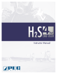
SPM® Well Service Pumps & Flow Control Products 2 Inch Light Weight Plug Valve (HSE approved) Operation Instruction and Service Manual Document P/N: Release Date: Revision: 2P37284 2/12/2013 B Copyright © S.P.M. Flow Control, Inc. 2013. All rights reserved. The manual must not be copied in whole or in part, in any form or by any means, and the information in it must not be disclosed to any person, or used for any purpose other than the specific purpose for which the manual has been provided, without the prior written consent of the company. SPM, DESTINY, SAFETY IRON, and DURALAST are trademarks of S.P.M. Flow Control, Inc.; WEIR is a trademark of Weir Engineering Services Limited Document P/N: Release Date: Revision: 2P37284 2/12/2013 B IMPORTANT SAFETY INFORMATION ENCLOSED. READ THIS AND ALL OPERATING AND MAINTENANCE INSTRUCTION MANUALS BEFORE OPERATING PRODUCT. THIS INFORMATION MUST BE AVAILABLE TO ALL PERSONNEL THAT WILL OPERATE AND MAINTAIN EQUIPMENT. IT IS THE RESPONSIBILITY OF THE EMPLOYER TO PLACE THE INFORMATION IN THIS MANUAL INTO THE HANDS OF THE OPERATOR OR TECHNICIAN. FAILURE TO READ, UNDERSTAND AND FOLLOW THIS DOCUMENT AND THE OPERATING AND MAINTENANCE INSTRUCTION MANUALS FOR ALL COMPONENTS AND ASSEMBLIES INCLUDED COULD RESULT IN SEVERE PERSONAL INJURY OR DEATH! Most SPM® products generate, control or direct pressurized fluids; therefore, it is critical that those who work with these products be thoroughly trained in their proper application and safe handling. It is also critical that these products be used and maintained properly!! DO NOT attempt to Open/Close any of the valves/components during operation. MISUSE, SIDE LOADING, IMPROPER MAINTENANCE, OR DISASSEMBLY UNDER PRESSURE CAN CAUSE SERIOUS INJURY OR DEATH! The following information is given in good faith and should aid in the safe use of your SPM® products. This information is not meant to replace existing Company's safety policies or practices. It is important to read and understand the “General Safety Data for all SPM® products” and the SPM® Product Safety Guide for “Union and Union End Products.” Both of these are available from Weir Oil & Gas. Personal Responsibilities: When using these assemblies, safety glasses, approved safety shoes and hard hat must be used. Hammering and lifting these assemblies must be done with caution. Where unions are present, read and understand the SPM® Safety Guide for Unions and Union End Products. Personnel should only hammer on makeup lugs and not strike union nut or valve body. Fractures can occur from repeated misuse. Excessive hammering can damage components. Proper leg lifting should be used when lifting. Back lifts should be avoided. Only the proper actuator bar should be used to turn SPM® plug valves. Valves require torque to operate. Makeshift bars can become dislodged easily and cause an accident or injury. Use only an SPM® actuator bar, SPM® part number 3P11542, for SPM® 2 inch Plug Valves. It is a personal responsibility to become knowledgeable and trained in the proper use and handling of this tool. Do not hammer on, or be around valve assemblies when pressure is present. Hand actuation (with the appropriate actuator bar) should be done only by specially trained personnel under direct supervisory instruction; and only when necessary due to application. NOTE: Refer to SPM® Operating & Maintenance Instruction Manuals and Procedures Included 2 Document P/N: Release Date: Revision: 2P37284 2/12/2013 B On Location: Proper transportation of SPM® plug valves is important. Racks that will secure valves and prevent accidental unloading are critical. Never transport any SPM® product in a fashion that would allow it to become dislodged and cause an accident. Valve unions should be clean and lightly oiled prior to each use. A visual inspection for damage should also be performed at this time. Union seals should be checked, and replaced when worn or damaged. Each valve has a size and pressure code designated on the valve. Use this code for proper mating and pressure limits. CAUTION: Since SPM® plug valves may be repainted in different colors for various applications; do not use factory color as a primary means of identification. Valve usage should be monitored by a qualified supervisor or foreman. Supervisory personnel must approve proper placement, position, and handling of all plug valves in the system. Only specially trained personnel under direct supervisory instruction, should actuate valves under pressure. Prior to applying pressure, valves should be greased in both the opened and closed position. This should be done before each use. If valve is excessively hard to operate, it should be removed and not used until repairs are made. It is sometimes necessary to turn valves when pressure is present. It is recommended that remote control actuators be used for this purpose. If this is not feasible, then only experienced specially trained personnel under direct supervisory instruction should perform this task. Venting flammable or explosive gases to the atmosphere through individual SPM® plug valves must be avoided. Choke manifolds are available from SPM® and should be used for this purpose. If used for bleeding, ample anchoring of the valve manifold must be done. Specially designed torture valves are available from SPM® for bleed off applications. WARNING: GASES, OR FLUIDS CONTAINING GASES, WILL CAUSE VALVES TO WHIP AND CAN CAUSE SERIOUS INJURY OR DEATH! When opening a SPM® plug valve under pressure, the initial torque to start the stem turning is always greater than the moving torque. You must position your body to be able to compensate for this change. Do not position any part of your body in the path of exit flow of the valve. Do not position the exit of any plug valve, used for bleeding, where rocks or debris may be picked up by the exit stream. If any valve becomes plugged, or does not operate properly, contact a supervisor immediately. DO NOT look into the end of the valve to check for debris, blockage, or for any other reason. 3 Document P/N: Release Date: Revision: 2P37284 2/12/2013 B If valve is slow to open or close, remove it from service. Do not hammer on the valve's actuator cap. It is recommended that a rate in excess of 42 feet per second be avoided. Rates above this will cause a more rapid wear and erosion. Flush clean and grease after each job with water and the proper SPM® valve grease. Use only an SPM® pressure rated gun for greasing. Special Precautions: Welding, brazing, or heating on SPM® plug valves is prohibited. Valve operation sometimes requires personnel to be around pressured lines. Experienced personnel only should be dispatched for this purpose. Exposure time should be a minimum. Always use remote controlled valves whenever possible. Never look into, or position yourself in, the path of the exit flow of the valve. Never alternate a valve's service. Acid service should never be followed by cold temperature service. When acid etching or erosion is present, replace the valve. SPM® offers specially designed valves for torture service, cold temperature service, H2S service, and aromatic service. Only valves designed and approved for these special services should be used in these applications. Each integral union connection is clearly marked with a pressure code (i.e. "1502", 15,000 psi). This pressure must not be exceeded. This code should also be used with mating unions. Improper mating can result in failures. All integral union connections must match (according to size, pressure rating, etc.). These connections must also match the service of the designated string they are installed in. 4 Document P/N: Release Date: Revision: 2P37284 2/12/2013 B Table of Contents SECTION I: GENERAL INFORMATION ............................................................................................................. 6 STANDARD SERVICE MODEL LISTINGS: ................................................................................................................. 6 STANDARD SERVICE REBUILD KITS: ....................................................................................................................... 6 H2S SERVICE MODEL LISTINGS: ........................................................................................................................... 6 H2S SERVICE REBUILD KITS: ................................................................................................................................ 6 PRODUCT DESCRIPTION: ................................................................................................................................... 7 SECTION II: INSTALLATION AND OPERATION ................................................................................................ 8 INSTALLATION DETAILS:..................................................................................................................................... 8 PRESSURE AND TEMPERATURE RATINGS: ................................................................................................................ 9 SECTION III: MAINTENANCE AND REPAIR .................................................................................................... 10 ALWAYS REMEMBER: .................................................................................................................................. 10 TOOLS REFERENCE PAGE: ................................................................................................................................. 11 MAINTENANCE REQUIREMENTS: ........................................................................................................................ 12 RECOMMENDED RE-GREASING PROCEDURE: ....................................................................................................... 14 BOM TABLE:................................................................................................................................................. 17 DISASSEMBLY AND INSPECTION: ....................................................................................................................... 19 REPLACEMENT AND ASSEMBLY: ......................................................................................................................... 23 VALVE TEST PROCEDURES: ................................................................................................................................ 27 TROUBLESHOOTING GUIDE: ............................................................................................................................. 28 SECTION VI: SERVICE AND SUPPORT ........................................................................................................... 30 SERVICE CENTER ORDER INFORMATION: ............................................................................................................. 30 WEIR OIL & GAS LOCATIONS: .......................................................................................................................... 31 5 Document P/N: Release Date: Revision: 2P37284 2/12/2013 B SECTION I: General Information Standard Service Model Listings: 2A29633 SPM® 2 inch light weight (LW) plug valve Standard Service Rebuild Kits: 2A30161 2A30162 2A30164 FULL REPLACEMENTS KIT (SEAL KIT, ELASTOMER KIT, PLUG, GREASE FITTING, NUT) SEAL KIT (METAL SEGMENTS, ELASTOMER KIT) ELASTOMER KIT H2S Service Model Listings: 2A36869 SPM® 2 inch light weight (LW) plug valve, H2S H2S Service Rebuild Kits: 2A37146 2A37180 2A37181 FULL REPLACEMENTS KIT (SEAL KIT, ELASTOMER KIT, PLUG, GREASE FITTING, NUT) SEAL KIT (METAL SEGMENTS, ELASTOMER KIT) ELASTOMER KIT 6 Document P/N: Release Date: Revision: 2P37284 2/12/2013 B Product Description: The SPM® 2 inch light weight (LW) plug valve is engineered with one thing in mind: Safety. It provides the following advantages to the Oil and Gas Industry: Compact/Lightweight Design Meets Health and Safety Executive (HSE) Requirements* Easy Assembly/ Disassembly DNV Certified CE Compliant (97/23/EC) Meets NACE MR0175 *HSE compliant products offer a safe lifting weight of 55 lbs or less to be lifted and carried by 1 person. Like other SPM® high pressure plug valves, the 2 inch LW plug valve is able to provide the same dependable service for applications such as: Acidizing Cementing Coil Tubing Fracturing Sand control Well Kill Sour Gas End Connections The SPM® LW plug valve is available with SPM® wing union connections. The nameplate will indicate the cold working pressure allowable for each assembly. The SPM® wing union connection on the SPM® plug valve is interchangeable with other union connections of the same size. Caution must be taken to avoid mixing in different ratings of wing connections. Failure to observe good judgment may lead to the failure of components and danger to personnel. Always verify working pressure ratings of each connection before use. 7 Document P/N: Release Date: Revision: 2P37284 2/12/2013 B SECTION II: Installation and Operation Installation Details: Caustic and corrosive fluids will cause deterioration of internal surfaces including structural and seal members, leading to early seal failure and derating of structural components. The use of inhibitors in the service fluid along with routine flushing of components after each job will retard the effect of wear and tear on the product. Internal friction in the SPM® plug valve is proportional to the working pressure and may vary significantly from one SPM® plug valve to the next. The SPM® plug valve should not be used as a choke. This will quickly wash out any product and is not recommended by Weir Oil & Gas Engineering. 8 Document P/N: Release Date: Revision: 2P37284 2/12/2013 B Pressure and Temperature Ratings: Pressure: The SPM® 2 inch LW plug valve is rated for non-shock cold working pressures up to 15,000 PSI. This pressure is never to be exceeded in the field. Certified testing at SPM® subjects the new product to a one time test of 1.5 times the rated working pressure. Field or customer controlled tests should be conducted with experienced personnel. Maximum working pressure should never be exceeded. Temperature: The maximum recommended operating temperature for the SPM® 2 inch LW plug valves is limited to the capability of the polymer seals to withstand elevated temperatures while maintaining seal integrity under pressure. The accepted limit for the standard seal material is 230F (110C). Practical experience has shown that there is a rapid drop off in seal life, when caustic fluids are handled at temperatures exceeding 160F (71C). Generally, chemical attack, gas absorbed, compression set or tearing is accelerated in these conditions. Minimum operating temperature of -22F (-30C) is acceptable for the elastomer seals. Contact Weir Oil & Gas Engineering for any application involving higher temperatures. WARNING: Observe instructions, cautions, and warnings as noted in this brochure. Failure to do so can lead to equipment damage, personnel injury, or loss of life. 9 Document P/N: Release Date: Revision: 2P37284 2/12/2013 B SECTION III: Maintenance and Repair WARNING: DISASSEMBLY UNDER PRESSURE CAN CAUSE SERIOUS INJURY OR DEATH! ALWAYS REMEMBER: 1. Always wear PPE (personal protective equipment). 2. Only qualified technicians should perform maintenance on SPM® products. 3. Always use SPM® supplied new kit parts for reassembly. 4. Clean all components thoroughly prior to re-assembly using protective clothing and safety glasses. 5. Check sealing areas of segments, plug and body for pitting or erosion. Failure in sealing can result if these areas are not smooth. 6. Reassemble with SPM® approved valve assembly grease. 7. Use only SPM® 2 inch LW replacement parts from SPM® to eliminate mismatched parts. 8. Use only SPM® body caps and actuator caps with SPM® valves. 9. Pressure test in accordance with instructions given in every repair kit prior to putting the valve into service. 10. Flush and grease valve thoroughly after each use. 10 Document P/N: Release Date: Revision: 2P37284 2/12/2013 B Tools Reference Page: ID 1 2 3 4 5 6 7 8 9 10 11 12 13 14 15 16 17 Description Safety Glasses Protective Gloves Steel Toe Boots Ear Protection Body Cap Wrench SPM® # 2P30029 400 Grit Sand Paper Soft Face Mallet Grease Gun SPM® part number P13335 Assembly Grease; single pack (SPM® # P36791) Actuator Bar SPM® part number 3P11542 7/8 inch socket 1-7/16 inch socket 3/4 socket wrench impact Teflon tape Hammer Pin Punch 11 Document P/N: Release Date: Revision: 2P37284 2/12/2013 B Maintenance Requirements: The SPM® 2 inch LW plug valve is made from high quality materials selected to provide the best service to the customer. However, the application of this product subjects it to handling fluids which are by their very nature corrosive and abrasive and operate at high velocities, and usually at high pressures. Some fluids may also require being conveyed at elevated temperatures. Combinations of any and all of these conditions will speed up the deterioration of internal surfaces including seals and seal surfaces. Without the benefit of scheduled maintenance to routinely service and inspect the condition of components, premature failure of parts can occur. This can lead to unnecessary material replacement along with the danger of injury to personnel. Proper knowledge and application of the plug valve is necessary for safe operation. It is recommended that a routine maintenance program include, at the very least: 1. Inspection of wall thickness loss 2. Routine replacement of O-rings and seals 3. Scheduled greasing of the Plug Valve after every fracturing job with recommended lubricants: • Val-Tex 1502 (Temp Range -20F to 400F) SPM® P/N P36791 • Val-Tex 972- (Temp Range -20F to 600F), SPM® P/N P32553 (Do not mix Assembly Greases – This will increase the amount of friction between internal components of the Valve. -- Contact Weir Oil & Gas Engineering for other approved grease) Frequent greasing will prevent the voids from occurring and will ensure easy operation of the valve. Please reference “Recommended Greasing Procedure” on Page 19. Once the plug valve body wall thickness falls below the minimums listed in Engineering Specification 1S19644 for Standard Service and 1S23257 for H2S Service flow products, it must be removed from service. Wall thickness may be measured by mechanical, sonic, or visual means. 12 Document P/N: Release Date: Revision: 2P37284 2/12/2013 B Maintenance Requirements (Cont.): Weir Oil & Gas recommends that the valve be serviced during the following: 1. Preventative Maintenance (After every Frac and/or stage job) Re-greasing the Plug Valve after every Fracturing and/or stage job will increase the life of the Plug Valve. Normal working operations will allow for grease loss if the plug valve is not maintained. This can create voids within the assembly. These voids will quickly accumulate sand and proppants thus increasing the force required to open/close the valve. Frequent greasing of the valve will ensure easier operation. Reference – “Recommended Re-Greasing Procedure” beginning on page 14. 2. Periodic Inspection Periodic inspections are required to ensure that all internal components of the valve are working properly and are to Weir Oil & Gas Engineering’s specifications. It is imperative that a qualified Weir Oil & Gas Technician follow the assembly/disassembly/inspection instructions beginning on page 19. Rebuild Kits are available through Weir Oil & Gas Service Centers. They are referenced on page 6. Periodic Inspection will include recertification of the Plug Valve which will include the following: Inspection of sealing surfaces, evidence of wear and pitting of all components. Disassembly New Kitting Ultra-Sonic Inspection / Minimum Wall Inspection Reassembly Pressure testing to 100% the product’s normal working pressure per SPM® Specification 4S12497 Section Magnetic Particle Inspection (Per Request) 13 Document P/N: Release Date: Revision: 2P37284 2/12/2013 B Recommended Re-Greasing Procedure: 14 Document P/N: Release Date: Revision: 2P37284 2/12/2013 B 15 Document P/N: Release Date: Revision: 2P37284 2/12/2013 B 16 Document P/N: Release Date: Revision: 2P37284 2/12/2013 B BOM Table: SPM® 2 Inch LW plug valve BOM BOM ID QTY DESCRIPTION 1 1 Grease Fitting 2 1 Stop Nut 3 1 Actuator Cap 4 1 Actuator Plate 5 1 Grease Retainer Gasket 6 1 Body Cap 7 1 O-ring 8 1 Seal Back-Up 9 2 Packing Seal 10 2 Packing Seal Back-Up 11 1 Plug 12 2 Side Segment 13 2 Seal Segment 14 2 O-Ring 15 1 Valve Body 16 1 2 Inch Seal Ring 17 1 Retainer Ring 18 3 2 Inch 1502 Retainer Segments 19 1 2 Inch 1502 Wing Nut 20 2 Segment Alignment Pin 21 2 Name Plate Screws 22 1 Name Plate Screws 17 Document P/N: Release Date: Revision: 2P37284 2/12/2013 B 18 Document P/N: Release Date: Revision: 2P37284 2/12/2013 B Disassembly and Inspection: WARNING: DISASSEMBLY UNDER PRESSURE CAN CAUSE SERIOUS INJURY OR DEATH. CAUTION: Any alteration of the SPM® valve is prohibited. Use only repair methods as outlined by SPM® valve service literature. Use only the proper SPM® repair tools. Weir Oil & Gas does not allow weld repair to be attempted on its product. Replacing worn components is a more effective and safe approach. Valves should be greased after each use. Use only the following SPM® gun and grease. Lube Grease: Val-Tex 972- (Temp Range -20F to 600F), SPM® P/N P32553 Gun Assembly: SPM® part number P13335 SPM® Repair Kits should be used for repair. Valve Body and all components must be clean and SPM® assembly grease used as recommended. Assembly Grease: Val-Tex 1502 (Temp Range -20F to 400F) SPM® P/N P36791 CAUTION: THE RATEDWORKING PRESSURE IS NOT TO BE EXCEEDED DURING SERVICE OR FIELD TESTING. 19 Document P/N: Release Date: Revision: 2P37284 2/12/2013 B Disassembly: 20 Document P/N: Release Date: Revision: 2P37284 2/12/2013 B 21 Document P/N: Release Date: Revision: 2P37284 2/12/2013 B 22 Document P/N: Release Date: Revision: 2P37284 2/12/2013 B Replacement and Assembly: For best results and most efficient use of time, SPM® recommends complete kit replacement. If any old internal parts are to be reused, after de-greasing, inspect them for wear and corrosion. If using used side and seal segments, thoroughly clean rust from sealing areas of seal segments that contact the plug and body. Scrape and lightly sand rust (with 400 grit sandpaper) from valve body surfaces which touch the center portion of the seal segments. Using 400 grit sandpaper, clean all other seal surfaces. Visually inspect all new parts and remove any foreign contaminants. 23 Document P/N: Release Date: Revision: 2P37284 2/12/2013 B 24 Document P/N: Release Date: Revision: 2P37284 2/12/2013 B 25 Document P/N: Release Date: Revision: 2P37284 2/12/2013 B 26 Document P/N: Release Date: Revision: 2P37284 2/12/2013 B Valve Test Procedures: WARNING: MISUSE, IMPROPER MAINTENANCE, OR DISASSEMBLY UNDER PRESSURE CAN CAUSE SERIOUS INJURY OR DEATH! Upon final assembly or reassembly of valve, a pressure test is to be performed as follows: WARNING: Prior to any pressure testing all air must be evacuated from the valve and pressure apparatus. Failure to do so could result in personal injury or death and/or sever damage to the valve. 1. Both ends of the valve are to be capped. Both caps must have pressure access ports as shown in Figure 3 below. Valve is to be tested so as to have pressure applied to both sides of plug - hence the need for pressure access ports at both ends of the plug. Figure 3: Pressure Access Ports 2. With caps in place and valve in the “OPEN” position and filled with liquid - (all air must be evacuated from valve at this point) - pressure valve slowly to maximum working pressure and inspect for visible signs of leakage, or failure to maintain pressure at the gauge. 3. Reduce pressure to zero and place valve in “CLOSED” position. 4. With the valve in “CLOSED” position - (again air must be evacuated from valve and system) - apply pressure slowly to one side of the valve, leaving the opposite side open, to a pressure equal to the maximum non-shock cold working pressure of the valve and maintain for a period of at least 3 minutes. Open and shut the valve. Repressurize the valve to its maximum non-shock cold working pressure and maintain for an additional 3 minutes. Inspect the valve during this procedure for any signs of leakage. Bleed the pressure off of the valve. 5. Reverse the valve and reconnect the pressure source to the opposite side of valve and repeat step #4 making sure all air is evacuated from valve and system. 6. Consult factory on any valve not performing properly during any phase of test or operation. 27 Document P/N: Release Date: Revision: 2P37284 2/12/2013 B Troubleshooting Guide: The following is intended as a general guide in helping resolve most problems encountered in repairing SPM® plug valves. PROBLEM: SOLUTION: A.) Valve leaks through bore when closed 1. Seal segments from two different manufacturers have been installed. (ALWAYS REPLACE SEGMENTS IN PAIRS FROM THE SAME MANUFACTURER). 2. Sealing area of segments or body scored or pitted. Resurface with 400 grit sandpaper or replace segments and/ or body. 3. Plug scored or worn. Replace plug. 4. ID of body or OD of seal segments not cleaned properly. Remove parts and clean out any contaminants. If the ID of the body is not cleaned properly, this will not let the O-ring or seal segments seat properly. ID of body may be too pitted to reuse. 5. Segments seal left out, not properly installed, or damaged during assembly. Remove segments, inspect seals and reinstall or replace as necessary. 6. Wrong actuator cap installed forcing plug to tilt to one side. Ensure actuator cap is from same manufacturer as body. (Always use SPM® actuator caps on SPM® valves). B.) Valve will not fully open. 1. Worn or damaged actuator cap or not an SPM® actuator cap. Remove and install SPM® actuator cap. (Always use SPM® actuator caps on SPM® valves). C) Valve leaks at body threads. 1. Body cap not tight. Re-tighten. Cap should bottom out. 2. Body cap O-ring scored or cut or no longer maintains seal. Replace O-ring. 3. Body cap damaged or worn. Replace cap. (Always use SPM® body caps in SPM® valves). 4. On SPM® 2inch valves, back-ring not installed. Install back-up ring above the O-ring with concave surface touching the O-ring. 5. Seal area scored or pitted in body. Clean up with 400 grit sandpaper or replace body. D) Seals swollen and softened or tacky. 1. Avoid solvents. Bune-N seals are not compatible with solvents such as toluene or xylene. If Buna seals are used, replace with Viton. E) Lower edge of plug chipped. 1. Always start plug into valve upon reassembly by hand to align chambers on plug and seal segments. Hammering plug before it is properly started can chip the plug’s leading edge and often score or damage the seal segments. Use only soft type hammers. 28 Document P/N: Release Date: Revision: 2P37284 2/12/2013 B PROBLEM: F) Valve leaks out the bottom. G) Valve leaks around plug top stem. H) Valve binding up. Hard or impossible to open or close. SOLUTION: 1. Body cap not SPM® product. Remove and reinstall SPM® body cap. SPM® bodies and body caps are designed differently to eliminate leaking cap problems. (Always use SPM® body caps in SPM® valves). 2. Actuator cap not SPM® product. Remove and re-install SPM® actuator cap. (Actuator caps from competitor valves will not work properly on SPM® valves). 3. Plug seal O-ring and back-up ring on bottom of plug not seated properly. Remove plug and reinstall O-ring and Nylon back-up ring. 1. Top plug seal O-ring and back-up scored or not seated properly. Replace or re-install. 2. Body cap not properly tightened. Re-tighten snugly until it bottoms out. 3. Body cap damaged or worn. Replace. 4. Body cap not SPM® product. Remove and re-install SPM® body cap. SPM® bodies and body caps are designed differently to eliminate leaking cap problems. (Always use SPM® body caps in SPM® valves). 1. ID of body not clean. Clean body and components. Reassemble. 2. Pins that hold detent spring may be interfering with actuator cap. Re-tighten pins in body. 3. Actuator cap is not SPM® product or is worn. Remove and install SPM® actuator cap and felt gasket. (Always use SPM® actuator caps on SPM® valves). NOTE: If problems are not resolved by using the troubleshooting guide, contact Weir Oil & Gas for assistance. 29 Document P/N: Release Date: Revision: 2P37284 2/12/2013 B SECTION VI: Service and Support Service Center Order Information: Weir Oil & Gas stocks a large inventory of genuine “original equipment” replacement parts. In order to expedite a parts order and avoid any delays, please provide the following information with your order: The part number and description of each item ordered. The quantity of each part, kit, or assembly ordered. The model number and serial number Your purchase order number. Specify method of shipment, complete shipping address, complete billing address and telephone number at the destination of the shipment. Weir Oil & Gas 601 Weir Way Fort Worth TX 76108 USA Tel: (817) 246 2461 Fax (817) 246 6324 www.weiroilandgas.com Copyright © S.P.M. Flow Control, Inc. 2013. All rights reserved. The manual must not be copied in whole or in part, in any form or by any means, and the information in it must not be disclosed to any person, or used for any purpose other than the specific purpose for which the manual has been provided, without the prior written consent of the company. SPM, DESTINY, SAFETY IRON, and DURALAST are trademarks of S.P.M. Flow Control, Inc.; WEIR is a trademark of Weir Engineering Services Limited 30