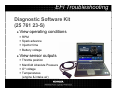
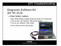
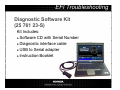
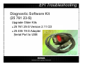
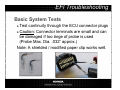
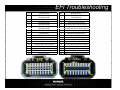
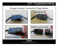
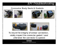
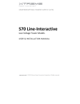
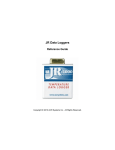
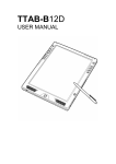
1
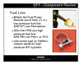
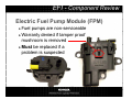
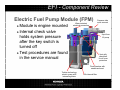
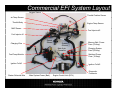
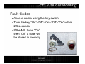
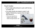
EFI - Component Review Wiring Harnesses All input and output signals go through two 18 pin all weather connectors } Attaches and locks to the ECU } EFI - Component Review Fuel Filter Plastic cased filter is installed before the pump 10 micron } Replace every : } 24 050 03-S 24 050 03-S 1500 Hrs Use Support Brackets 24 050 13-S 600 Hrs 25 5 050 42-S S 200 00 Hrs s 24 050 13-S 25 050 42-S EFI - Component Review F l Li Fuel Line Before the Fuel Pump Module use 6 6.5mm 5mm (¼ in.) in ) low pressure fuel line SAE R7 Low Permeation } After the FPM use high pressure fuel line SAE R9 Low L Perm. P or R12 } Use screw type or Oetiker® clamps made for high pressure EFI systems } EFI - Component Review Electric Fuel Pump Module (FPM) Standard mechanical or impulse pump is used to deliver fuel from the tank to the fuel pump module } Module delivers 39psi (2.7 bar) system pressure } EFI - Component Review Electric Fuel Pump Module (FPM) Fuel pumps are non-serviceable } Warranty denied if tamper proof mushroom is removed } Must be replaced if a problem is suspected } EFI - Component Review Electric Fuel Pump Module (FPM) Module is engine mounted } Internal check valve holds system pressure after the key switch is turned off } Test T t procedures d are found f d in the service manual } Water resistant electrical connection Pressure side quick connect Input from lift pump Vent with check ball for roll over protection Float chamber with needle and seat Turbine technology electric p pump p with internal regulator 22µ internal filter Commercial EFI System Layout Oxygen Sensor Throttle Position Sensor Air Temp Sensor Throttle Body Engine Temp Sensor MAP Sensor Fuel Injector #2 Fuel Injector #1 Charging Wire Speed Sensor System Ground Main 6 pin Connector Memory Batt. Power Fuse (10 Amp) Charging System Fuse (30 Amp) Switched Power Fuse (10 Amp) Fuel Pump Module Ignition Coil #1 Ignition Coil #2 Diagnostic Connector Starter Solenoid Wire Main System Power (Batt.) (Batt ) Engine Control Unit (ECU) EFI – System Operation From Key “On” to Running Key “On” energizes the system } A barometric pressure reading is taken from the MAP sensor and air temperature from IAT sensor to calculate “Air Density” } The Th engine i ttemperature t sensor helps determine how much gas is needed to start the engine } EFI – System Operation From Key “On” to Running Key “Start” energizes the starter } The speed sensor tells the ECU how fast the engine is rotating and where TDC is located } With all this input the engine i h has enough h information to start in “Batch Batch Fire Fire” } Always use a constant “On” key switch } EFI – System Operation From Key “On” to Running The MAP sensor is located next to one of the intake ports to help determine the correct stroke to run “Sequential Injection” } Within seconds the heated Oxygen sensor can measure the oxygen content in the exhaust to run in “Closed Closed Loop” Loop } ETS >140°F(60°C) closed loop active ETS >176°F(80°C) long term adaption EFI Troubleshooting Troubleshooting } Before faulting the EFI system make sure the engine is in good mechanical condition. Spark Compression Cylinder Leakage Test Crankcase Vacuum Check for debris in tank tank, plugged cap vent, kinked or pinched fuel lines etc. EFI Service Tool Kit 24 761 01-S Jumpers p Leads Schrader Valve Adapter Hose *DTI-037 High Pressure Clamps Injector Tester Injector Tester Hoses for Fitting “T” Fitting Fuel Pressure Gauge With Purge Valve 90° Adapter *See Parts Bulletin 228 EFI Troubleshooting Troubleshooting Electrical System Most EFI related problems are caused by poor wiring connections and/or faulty ground(s). } Even small amounts of corrosion can interfere with milliamp currents in the system. } EFI Troubleshooting Troubleshooting Fuel System To check for fuel delivery, attach a spark tester. } Crank the engine for 3 seconds, then remove the spark plug and check the tip for fuel. If no fuel is found: } Check the battery voltage. } Check the fuel pump fuse and connections. } Check fuel pressure. } EFI Troubleshooting Troubleshooting Fuel System } Test fuel pressure at the Fuel Pump Module using a fuel pressure gauge Warning: The fuel system is under high pressure (39 psi). The pressure will be relieved when the connection is opened. EFI Troubleshooting Fault Codes The Malfunction Indicator Light (MIL) signals a system fault code } MIL will remain “On” as long as the fault is current } If the MIL turns “On” then “Off” a code d will ill b be stored in memory as historic } EFI Troubleshooting Fault Codes Access codes using the key switch } Turn the key “On”-”Off”-”On”-”Off”-”On” within 2.5 seconds } If the MIL turns “On” then “Off” a code will b stored be t d iin memory } EFI Troubleshooting Fault Codes Codes are displayed as four digit power train codes (“P” code) } Each digit will be from 1-10 blinks followed by a pause (0 = 10 blinks) } The last code in a series i tto display di l will ill always be 61 } EFI Troubleshooting Fault Codes Fault codes will continue to cycle until the key is turned “Off” } If no other faults are present code 61 will display followed by a pause then the light will remain on } This is not code 62 but simply 61 with a pause before the light remains “On” EFI Troubleshooting Component p O² Sensor Heater Manifold Absolute Pressure Sensor (MAP) Intake Air Temperature Sensor (IAT) Coolant/Oil Temperature Sensor Throttle Position Sensor (TPS) “P”Code Description p Cause 0031 O² Heater Circuit High Voltage System voltage too high. Shorted connection. Faulty connection. 0032 O² Heater Circuit Low Voltage System voltage too low. Open connection/broken wire. Faulty sensor. 0107 MAP Circuit Low Voltage or Open Intake manifold leak. Open connection/broken wire (Black pin 11/green wire). Faulty sensor. 0108 MAP Circuit High Voltage Intake manifold leak. Shorted connection. Faulty sensor. 0112 Intake Air Temperature Sensor Circuit Low Voltage Shorted connection. Faulty sensor. 0113 Intake Air Temperature Sensor Circuit High Voltage or Open Open connection/broken wire. Faulty sensor. 0117 Coolant/Oil Temperature Sensor Circuit Low Voltage Shorted connection connection. Faulty sensor sensor. Shorted wire wire. 0118 Coolant/Oil Temperature Sensor Circuit High Voltage or Open Open connection/broken wire. Faulty Sensor. Shorted wire. 0122 TPS Ci Circuitit L Low Voltage V lt or Open Throttle Th ttl shaft h ft or b bearings i worn/damaged. /d d O Open connection/broken wire. Faulty sensor. 0123 TPS Circuit High Voltage Throttle shaft or bearings worn/damaged. Shorted connection. Faulty sensor. EFI Troubleshooting Component p Oxygen (O²) Sensor Fuel System “P”Code Description p Cause 0131 O² Sensor Circuit Low Voltage Open connection. Faulty sensor. 0132 O² Sensor Circuit High Voltage Shorted connection. Faulty sensor. 0171 High Maximum Adaptation Limit Exceeded Fuel inlet screen/filter plugged. Low system fuel pressure. TPS malfunction. Shorted connection. Faulty sensor. 0172 Low Maximum Adaptation Limit Exceeded System fuel pressure too high. TPS malfunction. Shorted connection connection. Faulty O² O sensor. sensor 0174 Lean Fuel Condition Fuel inlet screen/filter plugged. Low system fuel pressure. TPS malfunction. Open connection to O². Faulty O² sensor. 0201 Injector j 1 Circuit Malfunction Fuel supply pp y to injector j blocked or damaged. g Faulty injector. Bad fuse. Open connection/broken wire. Faulty sensor. 0202 Injector 2 Circuit Malfunction Fuel supply to injector blocked or damaged. Faulty injector. Bad fuse. Open connection/broken wire. Faulty sensor. 0230 Circuit Low Voltage or Open Bad fuse. Open connection/broken wire. 0232 Circuit High Voltage Shorted connection. Fuel Injector Fuel Pump Module (FPM) EFI Troubleshooting Component p “P”Code Description p Cause 0336 Crankshaft Position Sensor Noisy Signal Air gap incorrect. Loose sensor. Faulty/bad battery. Non-resistor sparks plugs installed. Shorted connection. Faulty sensor. 0337 Crankshaft Position Sensor No Signal S Air gap incorrect. Loose sensor. Shorted connection. Faulty sensor. 0351 Cylinder 1 Ignition Coil Malfunction Broken wire in harness (may not be visible). Shorted connection. Faulty sensor. 0352 Cylinder 2 Ignition Coil Malfunction Broken wire in harness (may not be visible). Shorted connection connection. Faulty sensor sensor. 0562 System Voltage Low Faulty voltage regulator. Bad fuse. Shorted connection. Corroded connection. Bad battery. 0563 System Voltage High Faulty voltage regulator. Shorted connection. Crankshaft Position Sensor Ignition Coil System Voltage End of Fault Codes 61 Code(s) end end. EFI Troubleshooting Diagnostic Software Kit (25 761 23-S) Displays power train codes } Identifies components/sensors/harness locations involved in each code } Guided diagnostics help identify the failure } EFI Troubleshooting Diagnostic Software Kit (25 761 23-S) } View operating conditions } RPM S k advance Spark d Injector time Battery voltage View sensor outputs Throttle position Manifold Absolute Pressure O² voltage Temperatures (engine & intake air) EFI Troubleshooting Diagnostic Software Kit (25 761 23-S) } View historic values Max. RPM, Battery Voltage, Engine & Intake Air Temperature Ti Time att Idle, Idl L Low, M Medium, di Hi High h speed d ranges Time at Low, Medium, High Loads Hour meters (current, trip & total) EFI Troubleshooting Diagnostic Software Kit (25 761 23-S) Kit Includes: } Software CD with Serial Number } Diagnostic interface cable } USB to Serial adapter p } Instruction Booklet EFI Troubleshooting Diagnostic Software Kit (25 761 23-S) Free Upgrade in Version 2.11 } If Less Than 2.11.0006 } www.kohler.diagsys.com EFI Troubleshooting Diagnostic Software Kit (25 761 23-S) Upgrade Older Kits } 25 761 25-S Version 2.11 CD $95.00 } 25 455 19-S Adapter Serial Port to USB $45.58 EFI Troubleshooting Diagnostic Software Kit (25 761 23-S) } Diagnostic cable attaches to the EFI system at the 4-pin diagnostic connector EFI Troubleshooting Basic System Tests Test continuity through the ECU connector plugs } Caution: Connector terminals are small and can be damaged if too large of probe is used (Probe Max. Dia. .032” approx.) Note: A shielded / modified paper clip works well. } EFI Troubleshooting Pin 1 2 3 4 5 6 7 8 9 10 11 12 13 14 15 16 17 18 Grey Connector OPEN (Not Used) OPEN (Not Used) MIL (Tan) Light Ground OPEN (Not Used) OPEN (Not Used) OPEN (Not Used) OPEN (N t U d) OPEN (Not Used) OPEN (Not Used) Ground (Black) Coil #2 (Purple) Ground Control OPEN (Not Used) OPEN (Not Used) OPEN (Not Used) OPEN (Not Used) Kill Wire (Wite) 10V Potential OPEN (Not Used) Diagnostic (White) Re‐Set Line Fuel Pump Power (Red) Switched OPEN (Not Used) Pin 1 2 3 4 5 6 7 8 9 10 11 12 13 14 15 16 17 18 Black Connector Coil#1 (Black) Ground Control Ground (Black) ECU (Drk Blue) Communication Crank Sensor HI (Yellow) INJ #1 (Drk Blue) Ground Control INJ #2 (Drk Green) Ground Control O² H t (D k G O² Heater (Drk Green) Ground Control )G dC t l IAT (Tan) Ground Control FPM (Pink) Ground Control 5V Return (Black) Main Sensor Power MAP Sensor (Lt Green) TPS (Drk Blue) TPS (Drk Blue) Crank Sensor LO (Purple) Oil Temp (Drk Green) Ground Return Power (Red) Switched 5V Return (Grey) Reference Voltage O² HI (Purple) Ground Control Memory Power (Red) Un‐Switched EFI Troubleshooting MAP Sensor Connector Details Lock Tab Slide L Slid Lock k ttab b outward. Press down on lock tab to release. Separate connectors EFI Troubleshooting Oxygen Sensor Connector Plug Details Pry lock tab back Separate connector bodies Compress p “Lock-Lever” EFI Troubleshooting Connector Body Seals & Gaskets To insure the integrity of sensor connection, visibly inspect the connector gasket / seal whenever the connector is opened EFI