1
X
INSTALLATION AND SERVICE
PROGRAMMING
This manual is for skilled service personnel only
DAMIAN S.R.L. - VIA RAGAZZI DEL ‘99 N°30 - 21053 CASTELLANZA (VA) - ITALY
Rev. M - 01
Vers. Software 0.5b or follow.
Serie "EUR7"
Rev. M - 01
Page 18
Serie "EUR7"
IMPORTANT:
This automatic vending machine is not intended for use by persons with reduced physical,
sensory or mental capabilities, or lack of experience and knowledge, unless they are
supervised or instructed on the use of the vending machine by a person responsible for their
safety. Children should be supervised to make sure that they do not play with the vending
machine.
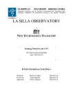
IDENTIFICATION, USE AND TECHNICAL DATA
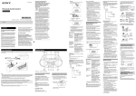
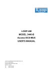
This manual refers to EUR7 series SNACK EUROPA automatic spiral vending machines,
with number of drawers, number and type of vending spirals varying from model to model.
FIGURE 1
FIGURE 2
MARKING PLATE / SERIAL NUMBER
KEYBOARD
FOOD ZONE
(Variable) Max 70cm.
MARKING PLATE /
SERIAL NUMBER
REFRIGERATION UNIT
MARKING PLATE
MAIN
SWITCH
The intended use for EUR7 series SNACK EUROPA automatic spiral vending machines
consists of automatically distributing solid products or products in solid package; prepackaged foods (snacks, bottled drinks, etc.) and non-food items.
For food products, make sure that the package is whole and that the products are in a good
state of preservation in conformity with the current applicable regulations concerning the
preservation of sold products.
The sale of toxic products (e.g. detergents) with food products is not allowed in the same
vending machine.
The vending machine may not be used to sell explosive material or material at risk of fire.
Rev. M - 01
Page 2
Serie "EUR7"
These models are manufactured in variations “-A” without refrigeration unit, “-R” with
Standard refrigeration unit, “-S” with Super refrigeration unit and “-L” with Super L
refrigeration unit with the characteristics shown in the following table:
Characteristics
Variation
EUR7B/x/xx-A EUR7B/x/xx-R
EUR7P/x/xx-S
EUR7L/x/xx-L
Power supply
Voltage
220-230V~
Frequency
50Hz
Rated power
160 W
460 W
490 W
490 W
Max. Rated power
260 W
620 W
650 W
650 W
Protection
IP24
(Only suitable for covered and protected places where it cannot be
rained on or sprinkled by water jets)
Refrig. System version
Assente
Standard
Super
Minimum internal
operating temperature
--
10 °C
(*) Food zone only
2 °C
Super L
3 °C ±2
Environment
Storage temperature
0
45 °C
Working temperature
5
32 °C
65 %
Max. relative humidity
Dimensions and Weights
Height
185 cm +/- 1 cm
Width
80 +/- 1 cm
Depth
85 +/- 1 cm
Maximum empty weight
230Kg
250Kg
250Kg
250Kg
Noise level
The vending machine emits an A-weighted sound pressure level below 70 dB.
(*) Food Zone = Variable height zone (up to a maximum of 70 cm) containing the drawers placed in the
lowest position in the vending machine (See Fig. 1).
- LEGEND OF SYMBOLS USED
Symbol
1
2
Rev. M - 01
Meaning
WARNING: NECESSARY OPERATION TO KEEP PEOPLE SAFE
CAUTION: THE OPERATION CAN DAMAGE THE MACHINE OR CAUSE IT TO
MALFUNCTION
Page 3
Serie "EUR7"
WARNINGS/CAUTIONS
The appliance should be be started up by skilled service personnel ONLY.
All operations described in this manual, especially all maintenance operations concerning the electrical
part, should be carried out by skilled technical service personnel ONLY.
The vending machine is equipped with a safety switch that allows powering up all electrical parts only
when the door is closed. With this switch it is possible to power up the vending machine even with the
door open, for example to perform the test procedure on the vending motors. Be careful that all moving
parts (spirals, sliding anti-theft panel, etc.) are not accidentally activated.
This automatic vending machine is not intended for use by persons with reduced physical, sensory or
mental capabilities, or lack of experience and knowledge, unless they are supervised or instructed on
the use of the vending machine by a person responsible for their safety. Children should be supervised
to make sure that they do not play with the vending machine.
1
Before checking any electrical part, move the main switch of the vending machine (See Figure
2) to the “OFF” position.
UNPACKING
Unpack the vending machine as follows:
Cut the clear plastic wrapped around the packing box and remove the various protective corners.
Free the keys that are tied together with the power cord on the lower rear part of the vending machine.
To remove the wood supports, lift the vending machine using a suitable forklift truck ( with a lifting
capacity of at least 350 Kg and lifting height of 25 cm from the ground) and remove the metal brackets
blocking the vending machine‟s feet by removing the fixing screws.
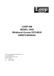
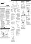
ASSEMBLY OF BASE PLATE (COVERING FEET)
There is a large package containing the base plate of the vending machine, inside the machine.
Remove the base plate from its packaging and position it under the door in front of the feet, pressing
against the base of the vending machine.
The base plate will remain fixed to the base thanks to the magnetic hooks it comes with.
It is possible, using 2 self tapping screws, attach further the base plate to the the vending machine.
BASE PLATE
SELF-TAPPING SCREWS
Rev. M - 01
Page 4
Serie "EUR7"
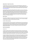
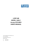
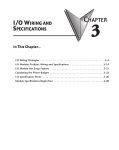
INSTALLATION
2
Install the vending machine in covered and protected places where it is not exposed to
inclement weather and cannot be rained on or sprinkled with jets of water.
MIN 8 CM
MIN 40
CM
FIGURE 3
MAX ± 2°
Place the vending machine in the point where it is to be installed, making sure that the minimum
distances shown in Figure 3 are guaranteed.
Also make sure that air can circulate freely in the rear and upper part; the room should be ventilated
regularly.
The vending machine must operate in a room that is in conformity with the information given in the table
on page 3.
Using the vending machine outside of these conditions could cause it to malfunction.
Adjust the height and alignment of the vending machine by means of the support feet with a 19 mm
open end wrench, making sure that all four of them rest correctly on the ground. When the vending
machine is not levelled properly it can be difficult to close the door.
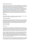
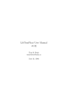
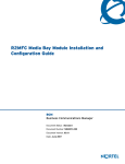
With the “wall anchoring bracket kit” accessory it is possible to anchor the vending machine to the wall
with two special spacers (See Fig. 4), as follows:
Screws from
above
FIGURE 4
Wall anchoring brackets
Nut from inside vending
machine
Drill and fasten to wall
Screw the two “wall anchoring brackets” on the top of the vending machine (see figure) with the screw
from above and a nut from inside the machine; remove the first drawer at the top to reach the position
easily.
- Place the vending machine in the desired position and mark the position of the brackets on the wall.
- Drill the wall and fasten the brackets using expansion bolts, making sure that the brackets are
positioned correctly.
- Position the vending machine inside the brackets and fasten it firmly with the screws from above and
the self-locking nuts from below (inside the machine).
Rev. M - 01
Page 5
Serie "EUR7"
POWER SUPPLY
1
The vending machine should only be connected to earthed electrical systems.
Before connection to the supply mains, make sure that the earthing system is present, that the supply
voltage is 220-230 Volt~, that the outlet to which the machine will be connected is in good condition and
approved for at least 10 Amp and that an omnipolar switch is installed upstream of it, i.e. that switches
off both power supply conductors with a single opening action (except for the earth conductor), with an
opening of the contacts of at least 3 mm. (It is recommended that the outlet have an insulated residual
current breaker).
Install the vending machine so that the power-supply plug is easily accessible after you install it.
Check the appearance of the power cord to detect possible abrasions or other defects of the sheath or
of the plug on the cord and replace it if necessary as described further on in this manual.
- POWER CORD REPLACEMENT
If it should become necessary to replace the vending machine‟s power cord, the H05VV-F replacement
cord, which is in conformity with standard CENELEC EN 60 335-1, is available from Damian; the
replacement should ONLY be carried out by skilled service personnel.
1
Before all operations on the power cord, make sure that the power-supply plug is disconnected
from its outlet.
GRILLE
CABLE GLAND
CABLE
Remove the rear grille of the cabinet by unscrewing its fixing screws, remove the cable gland from the
grille, open the cable gland and remove the cable.
Disconnect the cable socket from the electrical box and remove the cable to be replaced.
Repeat the operations described above in reverse order to install the new cable.
Check that the main switch found on the lower part of the cabinet (See Fig. 2) is in the “OFF” position
and insert the plug into the power-supply outlet, then move the main switch to the “ON” position.
When the vending machine door is closed, all of its electrical parts will be powered owing to the
pressure exercised by the door on the safety switch (black switch located on the right of the electrical
box. See Figure 2).
USING THE SAFETY SWITCH
The vending machine is equipped with a safety switch (See Figure 2) that allows powering up all of its
electrical parts only when the door is closed. When it is necessary to power up the vending machine
with the door open (for example, for loading products or programming), the safety switch can be armed
by inserting the special key and turning it 90°. To disarm the safety switch (in order to cut off power to
the electrical parts), turn the switch key 90° and remove it from the switch.
Rev. M - 01
Page 6
Serie "EUR7"
INSTALLATION OF PAYMENT SYSTEMS
1
The payment system installation and removal operations must be carried out with the power
supply switched off, moving the main switch to the “OFF” position.
- MDB PAYMENT SYSTEMS
Connect the payment system to the CPU card (2) being careful to connect the cable on the proper MDB
connector on the CPU card (See Figure 5).
Turn the vending machine on and programme it for operation in MDB mode (as described in
Attachment A, “Programming Sheet”); also refer to the documentation relative to the system itself for
the MDB payment system settings.
Enter the selling prices and any other programming data (Refer to Attachment A, “Programming
Sheet”).
The vending machine is now ready for use.
- EXECUTIVE PAYMENT SYSTEMS (OPTIONAL KIT)
The Executive Kit (optional) must be installed for operation of the executive payment systems.
Connect the Molex 15-pin female power connector of the vending machine to the corresponding
connector on the payment system (Refer to the payment system documentation).
Connect the serial connector of the payment system to the CPU card (2) using the special adapter
cable, being careful to connect the adapter cable on the proper connector (See Figure 5).
Turn the vending machine on and programme it for operation in Executive mode (as described in
Attachment A, “Programming Sheet”); turn the vending machine off and then on again and wait from 10
seconds to 2 minutes for communication with the payment system to be established. Remember to
programme the “value of each step" parameter (also called "coin scaling factor" or "minimum coin") to
the same value already entered during programming of the payment system (Refer to the payment
system documentation).
Enter the selling prices and any other programming data (Refer to Attachment A, “Programming
Sheet”).
The vending machine is now ready for use.
Rev. M - 01
Page 7
Serie "EUR7"
CIRCUIT BOARDS, SLIDING PANEL, PRODUCT DOOR.
EXECUTIVE connector
FTCA connector
PS1
(2)
DISPLAY
connector
KEYBOARD
connector
( 17 )
( 18 )
( 13 )
MDB connector
( 11 )
( 10)
( 3)
( 5)
FIGURE 5
( 5)
( 6)
(7)
Legenda
( 2 ) CL1 CPU circuit board
( 7 ) Closing control microswitch
( 3 ) FTCA sensor bars
( 10 ) Anti-theft sliding panel
( 5 ) Levers for locking the 'Push' door
( 11 ) Sliding panel motor
( 6 ) Two microswitches of the „Push‟ locking
( 13 )Beginning/end stroke microswitches
( 17 ) Sliding panel rack
( 18 ) Sliding panel motor pinion
Rev. M - 01
Page 8
Serie "EUR7"
OVERTEMPERATURE CONTROL (ONLY MODELS
EUR7P/X/XX-S)
In order to guarantee the preservation of the products for sale, the vending machine controls that the
internal temperature does not exceed a given threshold, called safety temperature, for a period longer
than the overtemperature time;
The overtemperature control function is managed through 3 parameters:
-
(A) Safety temperature
(B) Overtemperature time (Set).
(C) Restocking time
The overtemperature is only controlled in mode operating of the refrigeration unit = „Food & Snack‟,
setting the (A) Safety temperature parameter to a value below 40 °C
During normal vending machine operation, if the internal temperature exceeds the “Safety temperature”
(A) for a period longer than the “Overtemperature time” (B), the “ERR L09” error will be generated,
which will put the drawers set in the „Food zone‟ of the vending machine out of order.
The period of time in which the vending machine is off is always considered beyond the “Safety
temperature” (A).
If the vending machine is turned off and then on again (e.g. after restocking), the “Overtemperature
time” (B) is prolonged by a value equal to the one set in the “Restocking time” (C) parameter.
Each time it is turned back on, if the internal temperature exceeds the “Safety temperature” (A) but the
conditions for generating the “ERR L09” error have not occurred (see above), the following message
will appear on the display for approx. 15 sec.:
Overtemp XXXMin
YY,Y --> ZZ,Z °C
(1):SI (2):NO
XXX = Missing minutes,
YY,Y = Internal temperature,
ZZ,Z = Safety temperature.
(by missing minutes (XXX) we mean the minutes within which the internal temperature (YY,Y) must go
below the safety temperature (ZZ,Z) to prevent generation of the “ERR L09” error).
If the “ERR L09” error has been generated, entering into programming you will be asked if you wish to
reset the out of order by zeroing the error.
Press key 1 to reset the error
Press key 2 to NOT reset the error
Reset ERR L09
(1):YES (2):NO
IMPORTANT: the values of these three parameters should be set in accordance with the current
regulations applicable to the preservation of sold products. See the programming parameters in
Attachment "A" for how to set them.
N.B. To prevent false out of order indications following prolonged operator intervention, it is possible to
initialise the counters through the “Overtemperature counter reset” function (Refer to Attachment A,
“Programming Sheet”).
Rev. M - 01
Page 9
Serie "EUR7"
ANSWERS TO PROBLEMS THAT MIGHT ARISE
- ERROR MESSAGES THAT APPEAR ON THE DISPLAY
The following table shows the OFF messages that appear on the display when the vending machine is
out of order.
See Figure 5 for the numerical references in parentheses.
- Press key “1” to display further details about the type of out of order reported in the error
specification in parentheses.
- When any other key is pressed, automatic operation restoration will be attempted again, if
possible.
Message
code
OFF L01...
OFF L01a
OFF L01b
Message text
Problem description / solution
Temperature probe 1 error – These messages indicate a problem with the probe that measures the
st
temperature inside the vending machine. This probe is located on the inner right wall, near the 1 low
drawer towards the bottom of the vending machine.
Note: Probe operation is only checked at the moment the vending machine is turned on.
Probe 1 defective (Disconnected) – Probe 1 disconnected error.
- Turn the vending machine off and then on again, verify in programming that the
temperature value read by probe 1 is correct (see programming sheet). Try
touching the probe; if the value shown on the display does not change, check the
wiring and replace the probe if necessary.
- If, once the probe has been replaced, the problem is repeated, the fault might be
due to the CLP1 power board located in the electrical box.
(Short-circuit) - Probe 1 short-circuited error.
- Turn the vending machine off and then on again, verify in programming that the
temperature value read by probe 1 is correct (see programming sheet). Try
touching the probe; if the value shown on the display does not change, check the
wiring and replace the probe if necessary.
- If, once the probe has been replaced, the problem is repeated, the fault might be
due to the CLP1 power board located in the electrical box.
OFF L02…. Temperature probe 2 error – These messages indicate a problem with the probe that measures the
OFF L02a
temperature of the refrigeration unit evaporator. This probe is located in the refrigeration unit located
under the central plane of the machine. The refrigeration unit must be removed to access the probe (see
specific chapter).
Note: Probe operation is only checked at the moment the vending machine is turned on.
Probe 2 defective (Disconnected) – Probe 2 disconnected error.
- Turn the vending machine off and then on again, verify in programming that the
temperature value ready by probe 2 is correct and that the probe is not immersed
in ice; otherwise check the probe wiring and replace the probe if necessary.
- Check the vending machine configuration to verify if this probe should be
present. If not, carry out a new self-learning procedure as indicated in the
programming sheet attachment.
- If, once the probe has been replaced, the problem is repeated, the fault might be
due to the CLP1 power board located in the electrical box.
(Short-circuit) - Probe 1 short-circuited error.
- Turn the vending machine off and then on again, verify in programming that the
temperature value read by probe 2 is correct or that the temperature of the room
is not above 45 °C. If the error is not reset, check the probe wiring and replace
the probe if necessary.
- If, once the probe has been replaced, the problem is repeated, the fault might be
due to the CLP1 power board located in the electrical box.
OFF L02b
OFF L04
Rev. M - 01
Executive OFF
(Executive OFF) - No communication with the Executive system.
- Check the 24Vac power supply coming from the transformer and the connection
of the relative wiring with the 15-pin connector.
- Check the Executive signal wiring.
- If the problem is not resolved, check CPU card operation.
Page 10
Serie "EUR7"
Message
code
OFF L10…
Message text
Problem description / solution
FTCA vending sensor error – These error messages may appear when the vending machine is turned
on or right before a sale.
OFF L10a
OFF L10b
OFF L10c
OFF L10e
OFF L10f
OFF L10g
OFF L10h
OFF L13…
OFF L13a
OFF L13b
OFF L13e
OFF L13k
OFF L13l
Rev. M - 01
FTCA sensors OFF (Chk cable, Chang) – FTCA bars not connected
- Check the condition of the wiring and of the connections of the FTCA bars (3)
and replace wiring if necessary.
- If the problem persists, replace the FTCA bars (3) one at a time, starting from the
one on the right.
- If the problem is not resolved, check CPU card operation.
(Check LeftSensor) - Left hand FTCA bar error
- Check the condition of the wiring and of the connection of the left hand FTCA bar
(3) and replace it if necessary.
- If the problem is not resolved, check CPU card operation.
(Check RightSens.) - Right hand FTCA bar error
- Check the condition of the wiring and of the connection of the right hand FTCA
bar (3) and replace it if necessary.
If the problem is not resolved, check CPU card operation.
(High Light) - FTCA bars blinded error
- Perform the vending sensor test.
- Attenuate the possible source of external light that bothers the FTCA bars.
- If the problem persists, replace the FTCA bar/s (3).
(Low Light ) - FTCA bar darkened error
- Perform the vending sensor test.
- Check the state of cleanliness of the FTCA bars (3), eliminating any elements
that might obstruct passage of the light emitted by the LEDS.
- If the problem persists, replace the FTCA bar/s (3).
Sliding anti-theft panel errors. These error messages concern failures of the sliding anti-theft panel
(10) closing/opening system.
For a quicker check, perform the “Sliding door test” as explained further on.
(S.D. Mot. Fault) - Sliding panel motor short-circuited
Sliding Panel
- Check the operation of the sliding panel motor (11) and the relative wiring; replace
it if necessary.
(SD Mot. Disconn.) - Sliding panel motor disconnected
- Check the motor (11) of the sliding panel (10) and the relative wiring. Replace it if
necessary.
(Lock Pos.TimeOut) – Sliding panel motor movement error
At the end of an opening / closing cycle, the sliding panel does not close completely
or is not detected to be closed, or not open completely or is not detected to be open;
You are trying to make the sliding panel (10) work but the motor (11) idles or is
blocked.
- Check that the sliding panel (10) can slide freely, that the guides are clean and that
there is nothing preventing complete closing.
- Check that the motor gear (11) works correctly.
- Check the operation of the opening microswitch (13) and the relative wiring.
Replace it if necessary.
(Levers not down) – Error movement locking lever product removal door
During a cycle of opening / closing of the sliding panel (10) is not detected lowering
of the locking levers (5) of the door product.
- Check that the two lock levers (5) of the door product can move freely.
- Check that the two microswitches (6) of lock levers are correctly connected and
adjusted; make sure that the wiring is in good condition and replace them if
necessary..
Page 11
Serie "EUR7"
Message
code
OFF L20…
Message text
Problem description / solution
CL1 CPU (2) circuit board errors. These error messages concern failures of the vending machine‟s
circuit board.
(Restart - Change) - CPU card error
- Turn the vending machine off and then on again; if the problem persists, replace the
CPU card (2).
CL1 CPU SW Error (Reinstall SoftW.) - CPU card software error
OFF L20f
- Turn the vending machine off and then on again; if the problem persists, update the
OFF L20g
software.
- If the problem is not resolved after the update, replace the CPU card (2).
Unforeseen generic error.
OFF L50 (xxxx)
- Turn the vending machine off and then on again; if the problem persists, contact
the technical assistance service, providing the number in parentheses.
OFF L20a
OFF L20b
CL1 CPU Error
OTHER ANSWERS TO PROBLEMS THAT MIGHT ARISE
1
Before checking any electrical part, move the main switch to the “OFF” position (See Figure 7).
- MESSAGES RELATIVE TO MOTOR ANOMALIES.
During the selections or Diagnostic tests some motor anomaly messages might appear on the display;
these messages are listed below with the relative explanation, as well as some possible solutions to the
problem:
“Motor xx Disconnected” (NR)*: The motor is not connected to the CPU.
Check the connections and that the motor wiring is not interrupted.
Check correct operation of the motor microswitch and of the motor itself.
Try replacing, one at a time, the motor; the CPU card; the drawer and cabinet wiring.
“Motor xx Short Circuit” (NR)*: The motor is short-circuited.
Check the good condition of the motor itself.
Check that the motor and its connections are not wet.
Check the connections and that the motor wiring is not short-circuited.
Try replacing, one at a time, the motor; the CPU card; the drawer and cabinet wiring.
“Motor xx blocked” (R)*: The motor is blocked or absorbs too much current.
Check the correct assembly of the vending spiral.
Check the motor connections, especially the correct polarity of the power supply (+/-).
Check that the spiral or motor are not blocked by poorly arranged products or various residues.
Try replacing, one at a time, the motor; the CPU card.
“Motor xx Time Out Error” (R)*: The motor appears to work but the microswitch does not work correctly.
Check correct operation of the microswitch, of the motor and the good condition of the motor itself.
Check the motor connections, especially the correct polarity of the power supply (+/-).
Try replacing, one at a time, the motor; the CPU card.
“Motor xx Mot. Switch Err.” (NR)*: The motor appears to work but functions anomalously.
Even if the error can be reset and the motor appears to work, if this error is repeated it is advisable to
replace the motor.
If the error is repeated even once the motor has been replaced, the wiring must be checked;
“Motor xx Max 3 Selec Err.” (R)*: The motor has been put out of order after three consecutive sales of
the same motor without detecting that the product has dropped (See “FTCA Parameters” chapter).
Check that the spiral is hooked correctly to the motor.
Check the operation of the product drop control sensors (See “Diagnostics” chapter).
* = The error is automatically reset (R) or not reset (NR) upon turning on.
Rev. M - 01
Page 12
Serie "EUR7"
- UPON TURNING ON “WARNING OUT OF ORDERS DETECTED” IS DISPLAYED.
During normal vending machine operation, some malfunctions of some motors may occur. These
malfunctions generate errors that can be automatically reset by the vending machine (R)* or that can be
"not resettable" (NR)* and put the selection out of order (see above).
Even if operation of the selection has been automatically reset when the machine was turned on, the error
remains stored and must be deleted manually in diagnostics to keep the message from reappearing.
To check which motors and which problems have been stored, enter into “Diagnostic” in the “out of order
motors ” menu (see relative chapter).
- WHEN MAKING A SELECTION “SELEC. X-X IN OVERTEMPERATURE” IS INDICATED
If some selections are out of order indicated by the “Selection xx in Overtemperature” message, this is due
to the intervention of the “refrigerator safety control” (ERR L09 refrigeration unit timeout error) which has
put the drawers set in the vending machine „Food zone‟ out of order (see Overtemperature control”
section).
Entering in programming, you will be asked if you wish to restore operation by resetting the error.
Reset ERR L09
(1):YES (2):NO
Press key 1 to reset the error
Press key 2 to NOT reset the error
When key 1 is pressed the selections will be active again.
- WHEN MAKING A SELECTION “SELECTION X-X NOT ACTIVE” IS INDICATED
If some selections are out of order indicated by the “Selection x-x not active” message, this indicates a
problem relative to the storing of the configuration, because the selection made is not stored as active by
the vending machine.
Make sure that you have made the correct selection.
Carry out the “Motor Verify” procedure found in the diagnostic menu.
Carry out a new self-learning procedure of the motors through the reset of the circuit board.
If the motor is not recognised during the self-learning procedure, see the relative error further on.
- WHEN MAKING A SELECTION “SELECTION X-X OUT OF ORDER” IS INDICATED
If some selections are out of order, indicated by the “Selection x-x out of order” message, this indicates the
presence of a problem relative to the motor.
For a detailed analysis of the type of error that generated the out of order condition, use the “Diagnostic”
menu, “out of order motors” submenu and the preceding chapter “Motor anomaly messages”.
NOTE: It is possible to cancel the “Out of Order” condition of the motors without entering into programming
by pressing the PS2 key found on the CPU card for approx. 3 seconds (See Fig. 7).
- SOME MOTORS ARE NOT DETECTED DURING THE SELF-LEARNING PROCEDURE.
Check the wiring and good condition of the unrecognised motors, as well as the good condition and correct
insertion of the connectors on the bottom of the vending drawers.
After performing the above, carry out the procedure indicated for the “Disconnected motor” error.
- SEVERAL MOTORS RUN SIMULTANEOUSLY
When making a selection, two or more motors, even far apart, run simultaneously.
Check that a motor connection was not inverted following a maintenance operation. The motor with the
inverted wiring might not be among those that rotate simultaneously.
Check the good condition of the wiring of the motors of the vending spirals.
Replace the motor and/or connection wiring if necessary.
Make sure that the “Twin motors” function is not activated.
If the problem persists, make sure that the CPU card works and replace it if necessary.
Rev. M - 01
Page 13
Serie "EUR7"
- THE MACHINE DOES NOT REACH THE REQUIRED TEMPERATURE
1
Before carrying out any operation on the refrigeration unit and, in particular, before checking
any electrical part, move the main switch to the “OFF” position (See Figure 7).
Check the condition of the fuses (See the “Fuse check” chapter).
Make sure that dust and foreign materials do not block the refrigeration unit air passage.
Check that the condenser cooling fins are not blocked by dirt or foreign bodies and clean them if necessary
(to access the refrigeration unit, see the “Refrigeration unit disassembly and reassembly” chapter.
Check that the set temperature is neither too high nor too low, referring to the programming sheet.
Check that the internal air circulation fan works correctly.
Check that the refrigeration unit compressor works and that the cooling fan (located between the
compressor and the condenser of the refrigeration unit) works properly. If the compressor does not start
working when the LED on the card indicates that it is activated, check and if necessary replace the electric
starting capacitor, the Clicson or the amperometric relay located in the box mounted close to the
compressor.
With the compressor operating, check that the evaporator actually gets cold.
Check that the two evaporator fastening hooks located on the shelf under the first drawer are closed and
the evaporator properly hooked.
If it is not possible to identify the cause of the problem, contact an authorised service centre.
Rev. M - 01
Page 14
Serie "EUR7"
- FUSES
A
C
LED
B
D
F1
F2
F3
F4
MAIN
SWITCH
Press to cancel motors
“OUT OF ORDER”
SAFETY SWITCH
PS1
E
F5
Figure 7
Press to enter into
programming
The vending machine is equipped with fuses mounted as shown in the following table:
POSITION
INSCRIPTION
A
F1
TYPE
5x20 T6.3
( 6.3 A delayed 250 V )
B
C
F2
F3
PROTECTED
CIRCUITS
Refrigeration unit The vending machine does not
refrigerate
( 6.3 A delayed 250 V )
General
24-28V
5x20 T6.3
General 230V
5x20 T6.3
( ( 6.3 A delayed 250 V )
D
F4
5x20 T6.3
General 230V
( ( 6.3 A delayed 250 V )
E
F5
5x20 F1
( 1A rapid 250 V )
Rev. M - 01
CHECK WHEN
CPU power
supply
Page 15
The vending machine does not
work
The vending machine does not
work
The vending machine does not
work
The vending machine does not
work, the display does not turn on.
Serie "EUR7"
ROUTINE MAINTENANCE AND LUBRICATION
1
During the maintenance and lubrication operations, do not perform any operation other than
those indicated.
See Figure 5 for the references in parentheses.
Symbol
Periodicity
1 month
3 months
1 year
Check
Lubricate
- Correct operation of the door safety switch
- Correct operation of the sliding panel closing
and opening microswitches
- Check/cleaning of vending sensors (FTCA)
- Check/cleaning of the refrigeration unit
condenser fins.
N.B. (cut the periodicity by half for installations in
especially dusty locations)
- SAFETY SWITCH CHECK ()
1
During the safety switch check, do not perform any operations other than those indicated.
Check correct operation of the safety switch (15) by opening and reclosing the door with the
vending machine on; make sure that the vending machine turns off when the door is being
opened and that it turns on again only after it has been closed completely.
- SLIDING PANEL CHECK ()
Sliding panel (10) operation can be checked by performing a door closing and opening test
(see: programm.-> diagnostics ->Sliding panel test).
- CHECK/CLEANING OF „FTCA‟ VENDING SENSORS ()
To clean the LED barriers of the FTCA system (3), which are protected/hidden by the
sliding anti-theft panel during normal operation, it is necessary to open it, performing a
sliding panel (10) opening test (see: programm.-> diagnostics ->Sliding panel test). After
opening the sliding panel (10), use a brush to gently clean the LEDS (3), removing dust or
dirt that might obstruct passage of the light emitted by the LEDS.
- CHECK/CLEANING OF THE REFRIGERATION UNIT CONDENSER ()
Turn the vending machine off using the main switch, access the refrigeration, inspect the
condenser and clean it if necessary, removing any residues with a brush or
suctioning/blowing air. Make sure that dust is not raised during these operations; turn the
vending machine back on only after having replaced the refrigeration unit in its normal work
position.
Rev. M - 01
Page 16
Serie "EUR7"
ENVIRONMENTAL PROTECTION
Dispose of the cleaning and lubrication materials used in conformity with the regulations in
force.
Do not dispose of the equipment with domestic waste. Recycle this equipment to reduce
pollution and to guarantee maximum environmental protection; the materials must be
recycled in conformity with local, regional and state laws.
It is preferable to recover raw materials than to dispose of waste: equipment and packing
should be ecologically recycled.
Illegal disposal of the product by the holder involves the application of the administrative
sanctions provided for by the regulations in force.
1.
In the European Union
If the equipment is marked on the outside with this symbol, it should not be
disposed of with normal household waste.
Contact your local dealer for further information regarding disposal.
2.
In countries outside the EU
If you wish to get dispose of this product, please contact the local authorities for
information on the correct disposal method.
WARRANTY
Damian S.r.l. provides a warranty for its own products that is in conformity with the specific
national laws.
The warranty begins on the date shown on the sales document.
The warranty does not include damage caused by natural wear, overload, improper use or
any other breakdown not caused by a manufacturing defect.
The warranty conditions are given at the end of this manual.
Rev. M - 01
Page 17
X
Attachment “A”
PROGRAMMING SHEET
This attachment is an integral part of the manual
and must remain with it
DAMIAN S.R.L. - VIA RAGAZZI DEL ‘99 N°30 - 21053 CASTELLANZA (VA) - ITALY
Rev. M - 01
Vers. Software 0.5b or follow.
Serie "EUR7"
PROGRAMMING METHOD
PS1 key
PS1
Enter
Esc
(P) Programming key
TO ENTER INTO PROGRAMMING
Open the vending machine, power it up using the special key on the safety switch and press the pushbutton
(P) found on the CPU card of the vending machine (see the above figure) for about 2 seconds; avoid
reclosing the vending machine so as not to damage the safety switch.
1
When the safety switch is armed with the special key, do not perform any operations other
than those described.
TO CHOOSE THE PARAMETER THAT YOU WISH TO PROGRAMME
Select the menu using keys 1 (A) or 2 (C), the messages relative to the various menus will appear on the
second line of the display.
When the message relative to the desired menu appears, press the 3 (Enter) key to confirm.
The parameter name will appear on the first line of the display, the currently set value on the second line.
Select the menu parameter using the 1 (A) or 2 (C) keys; the messages relative to the various menu
parameters will appear in sequence on the first line of the display, until it starts again from the first
parameter.
When the message relative to the desired parameter appears, press the 3 (Enter) key to confirm.
TO CHANGE THE PROGRAMMED VALUE OF THE SELECTED PARAMETER
If “***>” appears on the second line followed by the current value.
Using the keyboard, write the desired value or press the 1 (A) key to increase or the 2 (C) key to decrease
the current value.
Press the 3 (Enter) key to confirm and return to the previous point or press the 6 (Esc) key to exit typing
without modifying the previous value.
Press the 4 (D) key to reset the proposed number.
In some cases press the 4 (D) key to move one digit to the left, until starting again from the first on the
right. Once all of the digits have been entered, press the 3 (Enter) key to confirm and return to the previous
point or press the 6 (Esc) key to exit typing without modifying the previous value.
TO EXIT PROGRAMMING
Press the 6 (Esc) key to return to the selection of the menus.
Press the “Programming key” (P) found on the CPU card of the vending machine for about 4 seconds or
press the 6 (Esc) key for a few seconds.
In any case, if no key is pressed for more than 120 seconds you will automatically exit the programming
phase.
Rev. M - 01
Pagina A - 2
Serie "EUR7"
DEFAULT = VALUE USED AUTOMATICALLY BY A NEW OR REINITIALISED CARD
GENERAL PARAMETERS
> MESSAGE LANGUAGE:
To establish the language of the messages that appear on the display.
Programming
General param.
[ Default: Italian ]
3
Language
Current value
> LCD CONTRAST SETTING:
To set the contrast of the LCD.
Programming
General param.
[ Default: 40 ]
3
LCD Contrast
Valore attuale
> OPERATING MODE:
To set the vending machine operating mode. Settable values:
„Test Vend‟ to operate in free sale, for example to perform the sale test.
„Executive‟ to operate with Executive payment systems;
„MDB‟ to operate with MDB payment systems;
Programming
General param.
[ Default: MDB]
3
Operating mode
Current value
N.B.: Make sure that when setting the parameter to „Test Vend‟, the vending machine allows sales of the
products without deducting the credit.
> CLOCK SETTING:
To set the current date and time.
Programming
General param.
3
dddd/mm/yy hh:mm
Current value
> CLOCK VISUALISATION ENABLE:
To activate or deactivate visualisation of the current time while the vending machine is awaiting a sale.
Settable values: „Disabled‟ (OFF), „Enabled‟ (ON).
Programming
General param.
[ Default: enabled]
3
Time Dsp Enable
Current value
> ENERGY SAVING PROGRAMMING:
To activate and set the parameters of the energy saving functions, which are only available if the vending
machine has the Vivilight Kit installed.
Energy Saving allows activating two separate energy saving functions:
- Save Mode function: Kicks in after a programmed vending machine inactivity time and reduces the
electrical consumption of the vending machine working, for example, on the reduction of the lighting and
the turning off of indicator lights and non-essential components.
- Night Mode function: Kicks in during programmed time intervals (for example, during nighttime hours)
after a period of vending machine inactivity and reduces the electrical consumption of the vending machine
to the minimum, working, for example, with the turning off of the lighting, of indicator lights and of nonRev. M - 01
Pagina A - 3
Serie "EUR7"
essential components. Furthermore, if the vending machine is NOT programmed to contain perishable
products ("Refrigerator operation” parameter other than “Food & Snack”), it allows setting a higher
operating temperature only activated during those time intervals.
The energy saving function setting modes are given below.
» SAVE MODE - ACTIVATION DELAY:
(Visible and programmable only with Vivilight Kit installed)
This parameter allows setting the time in minutes that must elapse, without anyone using the vending
machine, before the Save Mode function is activated (attenuation of the intensity of the LED lamps).
Settable values: 0 ÷ 120 minutes. Set the parameter to Zero „0‟ to deactivate the function.
[ Default: 0 minutes]
Programming
General param.
3
Energy Saving
->->->
3
SaveMode delay
Current value
» SAVE MODE - LIGHT INTENSITY:
(Visible and programmable only with Vivilight Kit installed)
This parameter allows setting the luminous intensity (in %) of the LED lamps that light up the display
window when the Save Mode function is activated. Settable values: 0 ÷ 100% .
Programming
General param.
[ Default: 100% ]
3
Energy Saving
->->->
3
Light in SaveMod
Current value
» NIGHT MODE - TIMETABLE:
(Visible and programmable only with Vivilight Kit installed)
This parameter allows setting the start and end times of the Night Mode function.
Set the times to 00:00 - 00:00 to disable the function.
Programming
General param.
[ Default: 19:00 – 07:00 ]
3
Energy Saving
->->->
3
Night Mode times
hh:mm – hh:mm
» NIGHT MODE - LIGHT INTENSITY:
(Visible and programmable only with Vivilight Kit installed)
This parameter allows setting the luminous intensity (in %) of the LED lamps that light up the display
window when the Night Mode function is activated. Settable values: 0 ÷ 100% .
Programming
General param.
[ Default: 100% ]
3
Energy Saving
->->->
3
Night Mode light
Current value
» NIGHT MODE - INTERNAL TEMPERATURE SETTING:
(Visible and programmable only with Vivilight Kit installed and “Refrigerator operation” other than “Food & Snack”)
This parameter allows setting the internal temperature of the vending machine when the Night Mode
function is activated. Settable values: 0 ÷ 50°C.
Programming
General param.
[ Default: 0°C ]
3
Energy Saving
->->->
3
Night Mode Temp.
Current value
The refrigerator temperature raising function is deactivated during the Night-Mode period if the
parameter is set to „0‟ (Zero) or to a value below the one set as standard internal temperature („Set Std
Temp 1‟ in the “Refrig. Param’s” menu).
This parameter can also be programmed through the “Refrig. Param’s” menu.
Rev. M - 01
Pagina A - 4
Serie "EUR7"
> REFRIGERATOR OPERATION:
(Visualisation only, programmable by reinitialising the card)
To visualise the operating mode of the refrigeration unit.
Programming
General param.
[ Default: Self-learned ]
3
Refrig.operation
Current value
The three possible operating modes, programmable by reinitialising the card, are:
- Food & Snack, enables management of the safety temperature for the Food zone.
- Drink & Snack, disables management of the safety temperature for the Food zone.
- OFF, disables operation of the refrigeration unit.
> FTCA PARAMETERS:
The series EUR7 vending machines can have an infrared system installed on the sides of the pick up tray
for detecting actual passage of the product (Sale has occurred).
This infrared system comprises a pair of infrared LED barriers which, during normal operation, are
protected/hidden by the sliding anti-theft panel, which is closed.
At each sale the FTCA barriers check the actual passage of the product; if it is not detected (Missed Sale),
the vending machine maintains the credit and, if the “Enable + 3 step” mode is active, it attempts to make
the spiral turn again by about ¼ turn, repeating the operation 3 consecutive times. If these attempts also
fail (or if the 3 step function is not active), the vending machine still keeps the credit stored in memory and
allows a new selection to be made.
When this function is selected it will be possible to set the following parameters of the FTCA function.
» ENABLING FTCA VENDING SENSORS:
To activate operation of the vending sensors that check passage of the product.
Settable values:
„0) Disabled „, FTCA deactivated;
„1) Enable NoStep‟ FTCA activated;
„2) Enable + 3Step‟ FTCA activated + 1/4 turn management.
Programming
General param.
[ Default: 2)Enable + 3Step ]
3
FTCA parameters
->->->
3
FTCA enabling
Current value
» MAXIMUM 3 FTCA SELECTIONS:
In the case of a missed sale, allows making up to a maximum of 3 other selections without losing the
credit. Settable values: „Disabled‟ (OFF), „Enabled‟ (ON).
Programming
General param.
3
FTCA parameters
->->->
[ Default: Enabled ]
3
Max 3 FTCA Selec
Current value
IMPORTANT: When this parameter is enabled, at the third consecutive sale of the same selection
without detecting the product drop, the motor is put out of order and the credit deducted.
> DECIMAL POINT:
Sets the position of the decimal point on the display; used to indicate prices with parts in cents; the value 1
corresponds to 1 decimal (0000.0). Settable values: 0 ÷ 3
Programming
General param.
Rev. M - 01
[ Default: 2 ]
3
Decimal point
Current value
Pagina A - 5
Serie "EUR7"
> CODE MODE
Allows to read the internal parameter software 'code mode'.
[ Read only ]
Programming
General param.
Code Mode
Current value
3
> VISUALISATION OF THE SW VERSIONS INSTALLED:
To visualise the software versions installed.
Programming
General param.
3
Software vers.
->->->
Press keys 1 and 2 to scroll through the versions of the various softwares.
> CARD REINITIALISATION:
To reinitialise the vending machine‟s CPU card, for example, after replacement with a new unprogrammed
one.
Programming
General param.
3
Default P. Reset
->->->
Proceed as follows to reinitialise the card:
1) enter into programming, General parameters, as described previously;
2) select Default P. Reset, this message appears on the display:
Password
00000
3) enter the value “12345” and confirm with 3, the card will delete some of the stored programming
parameters and will go automatically into “self-learning” mode.
The self-learning procedure occurs in the following phases:
Note: in the event of error in any point of the procedure, press the 6 key for a few seconds; the selflearning procedure will start over from the beginning.
A) This message appears on the display:
Self-learning
Language:Italian
after selecting the desired language, press 3 to confirm
B) This message appears on the display:
Self-learning
Conn. motors: xx
Check that the number of connected motors corresponds to those actually present in the vending machine;
if there is a discrepancy, proceed as described in the installation and service manual in the “Answers to
problems that might arise” chapter, “some motors are not detected” section.
press 3 to confirm
C) This message appears on the display:
Self-learning
Twin Motors:OFF
Press 3 if you do not wish to set twin motors in a single selection;
Otherwise select „Twin Motors: ON‟ to set pairs of motors near each other that you wish to make run
simultaneously with a single selection.
This message appears on the display:
Selection x-x
Current value
Select the motor that you wish to set coupled and press 3.
Rev. M - 01
Pagina A - 6
Serie "EUR7"
When you have finished setting all of the motors that you wished to couple (Twin Motors), press 6 to
continue the self-learning procedure.
D) This message appears on the display:
Self-learning
FTCA sensors:XXX
If the product drop sensors (FTCA) are installed on the vending machine, XXX = ON
If the product drop sensors (FTCA) are not installed on the vending machine, XXX = OFF
press 3 to confirm
E) The following message will appear shortly on the display:
Self-learning
Conn. probes x
Possible values: 0, 1, 2:
If the value is „0‟ (zero), there is no refrigerator probe connected; the following message will appear when
3 is pressed:
Refrig.operation
OFF
With “OFF” mode, refrigerator operation is deactivated; the self-learning procedure ends when the 3 key
is pressed and the vending machine returns to the programming menu. No other modes can be selected.
If the value is „1‟ (One), there is just one refrigerator probe connected; the following message will appear
when the 3 key is pressed:
Refrig.operation
Drink & Snack
It is possible to confirm “Drink & Snack” mode or, alternatively, select the “OFF” mode.
In “Drink & Snack” mode, refrigerator operation is activated without management of the safety temperature
of the food zone; the self-learning procedure ends when the 3 key is pressed and the vending machine
returns to the programming menu.
If the value is „2‟ (Two), there are two refrigerator probes connected; the following message will appear
when the 3 key is pressed:
or,
Refrig.operation
Refrig.operation
FOOD & Snack
Drink & Snack
It is possible to confirm “FOOD & Snack” mode or, alternatively, select the “Drink & Snack” mode or “OFF”.
Management of the safety temperature is activated when “FOOD & Snack” mode is selected; the following
message will appear when the 3 key is pressed:
Security Temper.
*>
7.0°C
The safety temperature value is displayed with the possibility of changing it; press 3 to confirm.
If an incorrect message appeared on the display during phase E), carry out the operations described in the
“Installation and service” manual, referring to the “OFF L01 and OFF L02” messages.
F) This message appears on the display:
*>
Code Mode
XXX
Self-learning of the internal parameter software 'code mode' : press 3 to confirm.
G) Once the last parameter has been confirmed, the self-learning procedure ends and the vending
machine returns to the programming menu.
Reinitialisation allows keeping all of the other settings active (e.g. “product prices”, “Price associations”,
etc.), avoiding reprogramming them.
Important: If it should be necessary to completely reset the circuit board with the total deletion of the
programming parameters, the reinitialisation procedure described above must be carried out, entering the
value “21613” in point 3).
Rev. M - 01
Pagina A - 7
Serie "EUR7"
» PROTECTED PARAMETERS:
Protected parameters are basic settings of the vending machine protected by „Password‟, parameters
that were set at the factory whose variation is not recommended unless suggested by the technical
support service.
Improper variation of these parameters could compromise the correct operation of the vending machine.
Programming
General param.
3
Protected param.
->->->
Password
00000
3
RESETTING OVERTEMPERATURE COUNTERS
(Visible and programmable only with „Refrigerator operation = Food & Snack‟)
If operator intervention is prolonged and the vending machine stays off or in overtemperature status for a
length of time close to the time set, it is possible that at the end of the intervention, when the operator has
already moved away, the vending machine is not able to bring the temperature back below the set
threshold in the residual time remaining. To prevent false out of order indications after prolonged operator
intervention, the various counters can be initialised through this function.
Programming
Reset Temp.
Programming
reset
3
Important: This function must be used in conformity with the applicable regulations in force regarding the
preservation of sold products.
MANAGEMENT OF SELLING PRICES
The series EUR7 vending machines can manage 44 price lines (i.e. 44 different prices) from L01 to L41
plus 3, S1-S2-S3 dedicated to direct selections, which will be associated with the individual vending
selections available. These 44 prices comprise the „A‟ price bracket, i.e. the basic prices that will be used
as reference in the price-selection association.
For the EUR7 vending machines it is possible to manage a second bracket of another 44 price lines, the
„B‟ price bracket, to be used, for example, for sales made with payment systems to which we wish to
assign dedicated prices, i.e. Cashless or RFID systems.
The prices of the „B‟ bracket will automatically be associated with the same selections associated with the
„A‟ bracket (For example, if price line 1 of the „A‟ bracket is associated with selection „2C‟, it will
automatically be associated with price line 1 of the „B‟ bracket also).
» „A‟ BRACKET SELLING PRICES:
The 44 available selling price lines of the „A‟ bracket can be set as follows:
Programming
Price management
[ Default: 2.00 for all selections. ]
3
Product Prices-A
->->->
3
Price-A N.: xx
Press keys 1 and 2 to scroll through the available price lines with xx going from L01 to L041 plus S1,
S2, S3, which correspond to the price lines for the direct selection buttons (max 3 optional buttons).
Press the 3 key to select the value “VVVVV” of the price line to be varied. Enter the new value, pressing
the numbers on the keyboard, confirm the price by pressing the 3 key again.
Note 1: if the entered value is not an exact multiple of the “Min. coin values” parameter (see further
ahead), it will automatically be rounded off and the new value will have to be reconfirmed with the 3 key.
Note 2: after enabling the direct selection, the first price lines proposals will be S1,S2,S3, which
correspond to the direct selection buttons (optional).
Once the selling price lines have been set, they can be associated with the available selections with the
„Price association‟ parameter.
Rev. M - 01
Pagina A - 8
Serie "EUR7"
> ENABLING OF THE „B‟ BRACKET SELLING PRICES:
(Visible and programmable only with „Operating mode = MDB‟ and/or RFID payment system installed)
To activate or deactivate management of the second price line bracket („B‟ price bracket).
Settable values: Enabled (ON), Disabled (OFF).
Programming
Price management
[ Default: Disabled ]
Price-B enabling
Current value
3
Activating management of the „B‟ selling prices, it will be possible to set the prices of the second price line
bracket.
» „B‟ BRACKET SELLING PRICES:
(Visible and programmable only with „Enabling B bracket prices enabled‟)
The 44 available selling price lines of the „B‟ bracket can be set as follows:
Programming
Price management
[ [ Default: 2.00 for all selections. ]
Product Prices-B
->->->
3
Price-B N.: xx
3
Press keys 1 and 2 to scroll through the available price lines (xx going from 01 to 44)
Press the 3 key to select the value “VVVVV” of the price line to be varied. Enter the new value,
pressing the numbers on the keyboard, confirm the price by pressing the 3 key again.
Note: if the entered value is not an exact multiple of the “Min. coin values” parameter (see further
ahead), it will automatically be rounded off and the new value will have to be reconfirmed with the 3 key.
> ENABLING DIRECT SELECTION:
(Programmable only with keyboard with direct selection system and FTCA installed)
To activate or deactivate management of the direct selection with keyboard with direct selection system
and FTCA system installed.
Settable values:
0)OFF Disabled
Selling direct selections Disabled.
1)ON ManualReset
Selling direct selections Enabled, with manual reset (Each time it is turned
back on is required the manual reset of empty)
2)ON Auto Reset
Selling direct selections Enabled, with auto reset (Each time it is turned back
on is automatically run the reset of empty).
[Default: Disabled]
Programming
Price management
3
Enabl. Dir. Sel.
Current value
Enabling the management of direct selections can be associated with direct selection buttons S1, S2,
S3, one or more selections.
» DIRECT SELECTION ASSOCIATION:
(Visible and programmable only with „Enabling direct selection enabled‟)
This function allows you to associate to direct selection buttons S1, S2, S3 one or more selections as
well as calling it a 'Direct Selection'. All the sections that are associated with a single button must
contain the same product. Pressing the key to Direct Selection, the vending machine starts sell from the
last spiral which provided the product. If this spiral was exhausted, the system FTCA will detect the
failure to selling; the system automatically attempt to deliver the product from the next spiral associated
with the same direct selection. If all spirals associated are exhausted, the selection will be automatically
put out of service.
Programming
Price management
Rev. M - 01
3
Assoc. Dir. Sel.
->->->
Pagina A - 9
3
Drawer : R-C
XX
VVVVV
Serie "EUR7"
Where L (line) indicates the number of the drawer (from the bottom) and C (column) indicates the
position on the drawer.
Where XX indicates the price line S1,S2,S3 dedicated to direct selections and VVVVV the relative price.
Press the 1 and 2 keys to scroll through the available selections.
Press the 3 key to confirm the current selection;
Press the button of direct selection from associate, or press 1 or 2 to choose from;; choosing "L01", the
selection is no longer associated with any direct selection button.
Press 3 to confirm the change. Repeat the same procedure for all selections from associate.
> PRICE ASSOCIATION:
This function allows associating a price of the „A‟ price bracket and the respective „B‟ bracket price to each
available selection.
Programming
Price management
Price assoc.
->->->
3
3
Drawer : R-C
XX
VVVVV
Where L (line) indicates the number of the drawer (from the bottom) and C (column) indicates the position
on the drawer.
Where XX indicates the price line and VVVVV the relative price.
Press the 1 and 2 keys to scroll through the available selections.
Press the 3 key to vary the association with the selling price line for the current selection; scroll through
the price lines with the 1 and 2 keys, after having selected the desired one, confirm it with the 3 key.
> DISPLAY OF THE SELLING PRICE:
Enables the display of the selling price of the product requested by the customer at the time of the sale.
Settable values: 'Enabled‟ (ON displayed), „Disabled‟ (OFF displayed).
Programming
Price management
[ Default: Enabled ]
3
Enable Price Dsp
Current value
EXECUTIVE PAYMENT SYSTEM PARAMETERS
(Visible and programmable only with „Operating mode = Executive‟)
> VALUE OF EACH STEP OR COIN SCALING FACTOR:
The value of the coins and the selling prices are always expressed as multiples of a base coin of minimum
value. During operation with Executive payment systems, this value must be the same as the one set in
the payment system. Settable values: 0 ÷ 1000.
Programming
Price management
[ Default: 00001 ]
3
Min. coin value
Current value
Note 1: if, during entering of the selling prices and of the values of the various coins and banknotes, they
are not multiples of the “Value of each step” parameter, they will automatically be rounded off.
MDB PAYMENT SYSTEM PARAMETERS
(Visible and programmable only with „Operating mode = MDB‟)
Some of these menus are only visible if a peripheral device is connected that foresees their use.
Rev. M - 01
Pagina A - 10
Serie "EUR7"
> MAXIMUM CREDIT:
To set the maximum credit value accepted by the MDB payment system. When the credit in the vending
machine reaches this value, the machine no longer accepts coins or banknotes.
Settable values: 0 ÷ 65535 (independent of the position of the comma, e.g. with 2 decimals the maximum
credit is 655.35). If set to 0, this control is disabled.
Programming
MDB parameter
[ Default: 0 ]
3
Maximum credit
Current value
> COIN RETURN PARAMETERS:
If there is an MDB coin return payment system installed in the vending machine, selecting this function it
will be possible to set the following operating parameters for it:
» COIN MINIMUM TO INDICATE NO CHANGE AVAILABLE
(Visible and programmable only if „MDB coin return‟ payment system installed)
To set the minimum value of the coins that must be present in each individual tube of the MDB coin box
below which the vending machine indicates no change available.
Settable values: 0 ÷ 15.
Programming
MDB parameter
[ Default: 5]
3
Coin retn.param.
->->->
3
MinTube NoChange
Current value
» COIN MINIMUM IN TUBES TO GIVE CHANGE:
(Visible and programmable only if „MDB coin return‟ payment system installed)
To set the minimum value of the coins that must be present in the tubes in an MDB payment system
below which the vending machine does not give change.
Settable values: 0 ÷ 5.
Programming
MDB parameter
3
Coin retn.Param.
->->->
[ Default: 2 ]
3
Min. coins tubes
Current value
» COMPULSORY SALE:
(Visible and programmable only if „MDB coin return‟ payment system installed)
If Enabled, the MDB payment system does not give change before a sale, to prevent it from being used
as a coin changer. Settable values: „Disabled‟ (OFF), „Enabled‟ (ON).
Programming
MDB parameter
[ Default: Disabled ]
3
Coin retn.Param.
->->->
3
Obligatory sale
Current value
» MANUAL EMPTYING OF THE COIN TUBES:
(Visible and programmable only if „MDB coin return‟ payment system installed)
If activated it enables the manual emptying of the coin tubes through the pushbuttons on the MDB
payment system. Settable values: „Disabled‟ (OFF), „Enabled‟ (ON).
The emptying of the coin tubes performed by the programming is carried out as described further on:
Programming
MDB parameter
Rev. M - 01
[ Default: Disabled ]
3
Coin retn.Param.
->->->
Pagina A - 11
3
Enab.Man.Dispens
Current value
Serie "EUR7"
» MDB SALES MODES:
(Visible and programmable only if „MDB coin return‟ payment system installed)
To select the sales mode with an MDB payment system. Settable values:
„0) Single NoChang‟, Single sale without change; at the end of the sale the change is cancelled.
„1) Single+Change‟ , Single sale with change; at the end of the sale the change is returned automatically
„2) Multi Vend‟, Multiple sale: the residual credit is returned only if requested:
Programming
MDB parameter
[ Default: „1) Single+Change‟ ]
3
Coin retn.Param.
->->->
3
Sale Modalit.MDB
Current value
> COINS AND TUBES:
If there is an MDB change return coin box installed in the vending machine, it will be possible to set the
reading and/or recognition of the quantity and/or value of coins or tokens present in the coin box tubes.
The following coin and tube parameters can be set by selecting this function.
» COINS MANAGED BY THE COIN RETURN SYSTEM:
(Visible and programmable only if „MDB coin return‟ payment system installed)
To read the value of the coins present in the MDB payment system tubes, and to enable or disable
acceptance of these coins; also to empty the coins present in the tubes:
Programming
MDB parameter
3
Coins and tubes
->->->
3
Coin nn vvvvv
In tubes xxx yyy
“nn” number of the coin,
“vvvvv” value of the coin,
“xxx” number of coins in the tube, if the tube is not enabled it displays “---“,
“yyy” =ON coin enabled, =OFF coin disabled
Press the 3 key to enable/disable the coin.
Press the 4 key to manually empty from 1 to 9 coins from the indicated tube.
Note 1: The value of the coins recognised by the payment system depends on the system itself; refer to
the relative documentation.
Note 2: With some MDB payment systems the parameter indicating the quantity of coins present could
be handled by the payment system itself. Refer to the documentation of the payment system in use.
» TOKENS PRESENT:
(Visible and programmable only if „MDB coin return‟ payment system that foresees the “Token” function is installed)
To read the number of tokens present in the MDB payment system tubes, and to enable or disable
recognition of these tokens:
Programming
MDB parameter
3
Coins and tubes
->->->
3
Token: n
In tubes xxx yyy
“n” number of the token,
“xxx” number of tokens in the tube, if the tube is not enabled it displays “---“,
“yyy” =ON token enabled, =OFF token disabled
Press the C key to empty the tube manually
> BANKNOTES AND STACKER:
If there is an MDB banknote reader installed in the vending machine, the reading and/or recognition of the
quantity and/or value of banknotes or tokens present in the MDB payment system will be possible.
The following banknote and stacker parameters can be set by selecting this function.
Rev. M - 01
Pagina A - 12
Serie "EUR7"
» BANKNOTES PRESENT:
(Visible and programmable only if an “MDB banknote reader” is installed)
To read which and how many banknotes are present in an MDB payment system and to enable
recognition of them:
Programming
MDB parameter
3
Banknote stacker
->->->
3
Bill nn vvvvv
Secur.H Act.ON
“nn” number of the banknote, “vvvvv” value of the banknote
“Secur.H” recognition security level high, “Secur.L” low
“Enabl.ON” banknote enabled, “Enabl.OFF” banknote disabled
Press 3 to enable/disable the banknote; press 4 to change the recognition security level.
Note 1: The value of the banknotes recognised by the payment system depends on the system itself;
refer to the relative documentation.
Note 2: the meaning and operation of the recognition security level depends on the payment system;
refer to the relative documentation.
» TOKEN
(Visible and programmable only if an “MDB banknote reader” that foresees the “Token” function is installed)
To enable the token recognised by an MDB banknote reader:
Programming
MDB parameter
3
Banknote stacker
->->->
3
* Token * vvvvv
Secur.H Act.ON
“Secur.H” recognition security level high, “Secur.L” low
“Enabl.ON” token enabled, “Enabl.OFF” token disabled
Press 4 to change the recognition security level.
Press the 3 key to enable/disable the token.
Note 1: the meaning and operation of the recognition security level depends on the payment system;
refer to the relative documentation.
> CASHLESS :
If one or more cashless payment systems are installed in the vending machine, it is possible to select the
price bracket to be associated with these systems.
» CASHLESS N.1 (PRICE BRACKET ASSOCIATION):
(Visible and programmable only if a „Cashless payment system‟ is installed)
If a cashless payment system is installed in the vending machine, it allows selecting the price bracket to
be associated with this system. Settable values: „Prices-A‟(Price bracket A), „Prices-B‟(Price bracket B).
Programming
MDB parameter
[ Default: Prices-A ]
3
Cashless
->->->
3
Cashless N.1
Current value
» CASHLESS N.2 (PRICE BRACKET ASSOCIATION):
(Visible and programmable only if a „Second Cashless payment system‟ is installed)
If a second cashless payment system is installed in the vending machine, it allows selecting the price
bracket to be associated with this system.
Settable values: „Prices-A‟(Price bracket A), „Prices-B‟(Price bracket B).
Programming
MDB parameter
Rev. M - 01
[ Default: Prices-A ]
3
Cashless
->->->
Pagina A - 13
3
Cashless N.2
Current value
Serie "EUR7"
RFID PARAMETERS
(Visible and programmable only if an „RFID payment system‟ is installed)
To set the parameters of the RFID payment system.
> RFID – PRICE BRACKET:
If an RFID payment system is installed in the vending machine, it allows selecting the price bracket to be
associated with this system.
Settable values: „Prices-A‟(Price bracket A), „Prices-B‟(Price bracket B).
Programming
RFID parameter
3
RFID Price brkt.
Current value
[ Default: Prices-A ]
> RFID – MACHINE CODES:
The correct machine codes (Machine code A and B) must be set in the vending machine in order for the
RFID payment system to work correctly. Contact the technical assistance service if problems should arise.
REFRIGERATOR PARAMETERS
(Visible and programmable only with „Refrigerator operation‟ other than “OFF”)
> INTERNAL TEMPERATURE READING:
To read the internal temperature of the vending machine.
Programming
Refrig. Param's
[ Read only ]
3
Probe 1 measure
Current value
> INTERNAL TEMPERATURE SETTING:
To set the internal temperature of the vending machine; Settable values: 0 ÷ 50°C..
Programming
Refrig. Param's
3
Probe 1 Temp.set
Current value
[ Default: 40°C ]
> NIGHT MODE INTERNAL TEMPERATURE SETTING:
(Visible and programmable only with Vivilight Kit installed and “Refrigerator operation” other than “Food & Snack”)
This parameter allows setting the internal temperature of the vending machine when the Night Mode
function is activated. Settable values: 0 ÷ 50°C.
The refrigerator temperature raising function is deactivated during the Night-Mode period if the parameter
is set to „0‟ (Zero) or to a value below the one set as standard internal temperature („Set Std Temp 1‟ in the
“Refrig. Param’s” menu).
This parameter can also be programmed through the “Energy Saving” menu in the “General Param’s”.
Refer to the “Energy Saving” section for further information on this function.
Programming
Refrig. Param's
3
Night Mode temp.
Current value
[ Default: 0°C ]
> REFRIGERATION UNIT WORKING TEMPERATURE READING:
(Only visible if 2nd refrigerator probe present)
To read the working temperature inside the refrigeration unit evaporator.
Programming
Refrig. Param's
3
Probe 2 measure
Current value
[ Read only ]
> SAFETY TEMPERATURE:
(Visible and programmable only with „Refrigerator operation = Food & Snack‟)
To read the safety temperature for the sale of food products; see the Overtemperature control section
and the description of the “ERR L09” error message for the description.
Rev. M - 01
Pagina A - 14
Serie "EUR7"
Settable values: 0 ÷ 45°C.
To deactivate this function, set it to ≥40°C.
Programming
Refrig. Param's
[ Default: 45 °C ]
3
Security temper.
Current value
> OVERTEMPERATURE TIME:
(Visible and programmable only with „Refrigerator operation = Food & Snack‟)
To set the time beyond which the internal temperature must not exceed the safety temperature; see the
Overtemperature control section and the description of the “ERR L09” message for the description.
Settable values: 0 ÷ 1440 minutes.
Programming
Refrig. Param's
[ Default: 30 minutes]
3
Overtemper. time
Current value
> RESTOCKING TIME:
(Visible and programmable only with „Refrigerator operation = Food & Snack‟)
To set the time that is added to the overtemperature time each time restocking takes place (vending
machine turned on); see the Overtemperature control section for the description. Settable values: 0 ÷
1000 minutes.
Programming
Refrig. Param's
[Default: 120 minutes]
3
Refueling time
Current value
> CONNECTED PROBES:
To read the number of refrigeration unit control probes that are connected.
Programming
Refrig. Param's
3
[ Read only ]
Connected probes
Current value
EVA-DTS PARAMETERS
> PASSWORD CODE RESET (EVA-DTS):
To reset the “Security” and “Passcode” codes foreseen by the DDCMP protocol (EVA-DTS) to prevent
anyone from being able to access and download the data relative to the vending machine proceeds using
an IRDA handheld device.
Programming
EVA DTS param.
3
Reset Passcode
->->->
3
Password
00000
Thanks to these protection codes, the data can be downloaded only if those set on the handheld device
coincide with those acquired previously by the vending machine.
If the 2 codes do not correspond, the following error message will appear:
DDCMP error
9071
In this case, the codes acquired by the vending machine must be reset (Reset Passcode) by entering the
password.
At this point the vending machine has no protection code and will reacquire a new one at the time of the
next connection with a handheld device that has a code other than 0 set .
Rev. M - 01
Pagina A - 15
Serie "EUR7"
AUDIT PARAMETERS
NOTE: It is possible to display a minimum list of sales data on the automatic vending machine. If an MDB
system is installed, the vending machine collects more detailed data, available in the EVA-DTS format.
> PARTIAL COUNTER OF NUMBER OF VENDING MACHINE SALES:
To read the total number of vending machine sales since the last reset.
Programming
Audit data
3
Partial n. sales
Current value
> PARTIAL COUNTER OF VALUE OF VENDING MACHINE SALES:
To read the total amount collected by the vending machine since the last reset.
Programming
Audit data
3
Part.Val.Sales
Current value
» COUNTER OF NUMBER OF SALES PER SELECTION:
To read the total (absolute and partial since the last reset) number of sales for each individual vending
machine selection.
Programming
Audit data
3
Num.Sales Motors
->->->
3
Motor :
P xxxxx
xx
T xxxxx
COUNTER OF NUMBER OF SALES PER LINE (SALES PRICE):
To read the total (absolute and partial since the last reset) number of sales for each product price line.
Programming
Audit data
3
Num.Sales Lines
->->->
3
Price N. : xx
P xxxxx T xxxxx
> GENERAL TOTAL NUMBER OF VENDING MACHINE SALES:
To read the general total number of vending machine sales:
Programming
Audit data
3
Tot.Num.Sales
Current value
> GENERAL TOTAL VALUE OF VENDING MACHINE SALES:
To read the general total of the amount collected by the vending machine:
Programming
Audit data
3
Tot.Val.Sales
Current value
» AUDIT DATA RESET:
To reset the Partial totals counted by the vending machine.
Programming
Audit data
Rev. M - 01
3
Audit Data Reset
->->->
Pagina A - 16
3
Audit Data Reset
(1):YES (2):NO
Serie "EUR7"
DIAGNOSTICS
N.B. the programming TimeOut is disabled in the Diagnostics submenus, therefore, it is only possible to
exit programming manually, using the appropriate keys.
> OUT OF ORDER MOTORS:
Select this item to see which motors have generated an Out of Order condition.
The out of orders are also listed in this menu
Programming
Diagnostics
3
OutofOrder Mot.
->->->
3
Motor : x.x
Out of Order
The following message will appear if there are no motors out of order:
No motor
Out of Order
If there are motors out of order, you can use the 1 and 2 keys to scroll through the list of motors; the
current motor will be activated when the 3 key is pressed; the following message will appear if there is
still a malfunction:
Error
xxxxxx
Where “xxxxxx” is the detected error. See the “Installation and service” manual, "Problems and relative
solutions” chapter, “Motor anomaly messages” section for the list of anomalies and relative solutions.
It is important to keep in mind that even possible out of orders that are automatically reset (R) by turning
the vending machine on and off are also listed in this menu (see “Motor anomaly messages" chapter
indicated above). The indication remains until the out of order has been reset as indicated below.
Press the 4 key to cancel the Out of Service condition of the current motor. The following message will
appear on the display:
Motor : x.x
Reset
Press the 6 key to exit the submenu.
NOTE: It is possible to cancel all of the “Out of Order” conditions of the motors without entering into
programming by pressing the PS2 key found on the CPU card for approx. 3 seconds (See Page A-2).
> MANUAL MOTOR TEST:
Select this item to test the individual motors, making them carry out a sales cycle.
Programming
Diagnostics
3
Mot Manual Test
->->->->
3
Motor
: x.x
Use the 1 and 2 keys to scroll through all of the motors detected during the self-learning procedure.
When the 3 key is pressed briefly, the current motor will be activated; the following message will appear if
a malfunction occurs:
Error
xxxxxx
Where “xxxxxx” is the detected error. See the “Installation and service” manual, "Problems and relative
solutions” chapter, “Motor anomaly messages” section for the list of anomalies and relative solutions.
Rev. M - 01
Pagina A - 17
Serie "EUR7"
The general test cycle will begin instead when the 3 key is kept press for about one second; during this
cycle, the vending machine will carry out a sales cycle in sequence for each gearmotor detected by the
self-learning procedure, starting from the current motor up to the last motor of the vending machine. In the
event of a defect on one of the motors, the test will be interrupted and the relative error message
displayed.
The general test cycle will be interrupted when keeping any key pressed until the end of the sales cycle of
the current motor.
Press the 6 key to exit the submenu.
> MOTOR VERIFY:
Select this item to perform a quick check of the condition of the motors.
This function does not change the vending machine configuration detected during the self-learning
procedure; it simply limits itself to comparing the current condition of the motors with that of the last selflearning procedure performed.
Programming
Diagnostics
Motor Verify
->->->->
3
3
Motor
: x.x
[Where x.x scrolls the motors in sequence]
If errors should be detected during the check, the check itself stops and the following message appears:
Error
xxxxxx
Where “xxxxxx” is the detected error. See the “Installation and service” manual, "Problems and relative
solutions” chapter, “Motor anomaly messages” section for the list of anomalies and relative solutions.
From these error conditions it is possible to make the check sequence continue by pressing the 3 key, or
end it with the 6 key.
One of the following messages will appear at the end of the check sequence:
Check incorrect
Conn. motors: XX
This means that anomalies and/or differences between the current configuration and the one detected
during the last self-learning procedure have been detected; XX indicates the number of the currently
recognised motors.
Check OK
Conn. motors: XX
This means instead that anomalies and/or differences between the current configuration and the one
detected during the self-learning procedure have not been detected; XX indicates the number of the
recognised motors.
In the event of “Check OK”, at the end of the motor check cycle the vending machine‟s original
configuration is completely restored and the out of orders reset.
N.B.: at each check the motors rotate just a few degrees; therefore, repeating the check several times in
succession, the motors could lose alignment; we therefore recommend realigning the motors, for example
by carrying out a manual motor test, as described previously in this manual.
Rev. M - 01
Pagina A - 18
Serie "EUR7"
> MOTOR SELF-LEARNING:
Select this item to repeat the self-learning of the motors present in the vending machine; this action is only
allowed if a password is set in the protected parameters menu.
Programming
Diagnostics
Motor Slearning
->->->->
3
Self-learning
Conn. motors: xx
3
> SLIDING PANEL TEST
Select this item to perform the sliding anti-theft panel operation test.
Programming
Diagnostics
3
Anti-tft p. test
->->->->
3
M L C P Pot TTot
X Y K W ZZZ ZZZZ
When the following message appears on the display:
M L C P Pot TTot
X Y K W ZZZ ZZZZ
Press the 1 key to open the anti-theft panel.
Press the 2 key to move the anti-theft panel in the closed position allowing the product door opening
Press the 3 key to close the anti-theft panel.
M - Sliding Panel microswitch:
X = 1 Micro-switch pressed, Sliding Panel fully closed.
X = 0 Micro-switch not pressed, Sliding Panel fully open, or not fully closed.
L - Locking lever product removal door Micro-switch:
Y = 1 Locking lever lowered, product removal door Locked.
Y = 0 Locking lever up, product removal door Unlocked.
C - Product removal door opening Micro-switch:
K = 1 Micro-switch pressed, product removal door Closed.
K = 0 Micro-switch not pressed, product removal door Open.
P - Parameter detected by the electronics that indicates the position of sliding panel.
W = 1 Sliding Panel fully closed.
W = 3 Sliding Panel partially closed.
W = 5 Sliding Panel fully open.
Press the 6 key to exit the submenu.
Rev. M - 01
Pagina A - 19
Serie "EUR7"
> VENDING SENSOR TEST (FTCA)
Select this item to test the vending sensor circuit (FTCA).
Programming
Diagnostics
3
FTCA sens. test
->->->->
3
Left
OK+
Nois
OK+
Righ
OK+
The following message will appear on the display:
Left
OK+
Nois
OK+
Righ
OK+
The “Left” and “Righ” parameters indicate the degree of intensity of the light detected by the sensors.
The “Nois” parameter indicates the level of intensity of the noise detected by the sensors.
We understand the “status” of the FTCA system through these three parameters.
Possible values:
OK+ : The level is good
OK : The level is fair
OK - : The level is minimal but sufficient
ERR : The level is insufficient
If one of the three parameters should be at the “ERR” level, the FTCA infrared system will be out of order
and an “OFF L10…” message will be displayed (see OFF message table for details).
When the following message appears on the display:
Left
OK+
Nois
OK+
Righ
OK+
The following message will appear when the 3 key is pressed:
FTCA 2 Enabled
Mot:yy Sens:xxx
When the 3 key is pressed it will be possible to carry out a test delivery (sale) on the yy selection.
For each product delivered (sold) a “beep” will be emitted each time an object passes in front of the
sensors and a different value will appear on the display in the “Sens” field; through this information we
understand that the FTCA system works correctly; the higher the number (Sens), the easier it will be for
the FTCA infrared system to detect the delivered product.
Press the 1 and 2 keys to change the selection indicated by the “Mot” parameter.
Press the 6 key to exit the submenu.
Rev. M - 01
Pagina A - 20
Serie "EUR7"
SUMMARY TABLE:
Menu
General
General
General
General
Param’s
Param’s
Param’s
Param’s
Parameter
(*) Memorandum to be filled out after the programming under way
Meaning
Default
Min-Max
Message language
General Param’s
Language
LCD contrast
Operating mode
DDD DD/mm hh:mm
DateTime Dsp
Enable
SaveMode delay
Light in SaveMode
NightMode
timetable
NightMode Light
Light intensity in NightMode
0 ÷ 100%
100%
General Param’s
NightMode temp.
Temperature setting in
NightMode
0 ÷ 50 °C
0
General Param’s
Refrigerator
operation
Refrigerator Operation
General Param’s
FTCA enabling
Vending sensor enabling
0)Disabled,
1)Enable Nostep,
2)Enable +3step
General Param’s
FTCA max 3 sel.
FTCA max 3 selections
Enabled Disabled
General
General
General
General
General
Decimal point
Code Mode
Software versions
Default P. Reset
Protected param.
Decimal point position
0÷3
General Param’s
General Param’s
General Param’s
General Param’s
Param’s
Param’s
Param’s
Param’s
Param’s
Reset Temp.
Italian
LCD contrast setting
40
Operating mode
MDB
Clock setting
Clock enable
Enabled Disabled
Activation delay in SaveMode
0 ÷ 120 minutes
Light intensity in SaveMode
0 ÷ 100%
Enabled
0
100%
NightMode Activation
Timetable
19:00÷7.00
Aut.
Internal code software
2)Enable +
3step
Enabled
2
Read only
Displays software versions
Card reinitialisation
Password required
Protected parameters
Password required
---
Reinitialise overtemperature times
Price management Price-A N.:xx
Value of each of the 44
associable „A‟ bracket prices
0 ÷ 635.35
2.00
Price management Price-B enabling
Enabling „B‟ price bracket
Enabled Disabled
Disabled
Price management Price-B N.:xx
Value of each of the 44
associable „B‟ bracket prices
0 ÷ 635.35
2.00
Price management Enabl. Dir. Sel.
Enabling direct selections
0)OFF Disable,
1)ON Manualreset,
2)ON Auto Reset
Price management Drawer L-C
Direct selection association
S1-S2-S3
Price management Drawer L-C
Price associated with drawer
(Line) L, (column) C
0 ÷ 44
Price management Enable Price Dsp
Display of the selling price
Enabled Disabled
Enabled
Executive
parameters
Min. coin values
Coin scaling factor
0 ÷ 1000
000.01
MDB parameters
Maximum credit
Maximum accepted credit
0 ÷ 635.35
MDB parameters
MinTube NoChange
Minimum coins to turn “no
change” indicator light on
5
MDB parameters
MinTube Change
Minimum coins for giving
change
2
MDB parameters
Obligatory Sale
Compulsory sale
Enabled Disabled
Disabled
MDB parameters
Enab. Man.
Dispens
Manual emptying of the coin
tubes
Enabled Disabled
Disabled
Rev. M - 01
Adjusted
to (*)
Pagina A - 21
----
----
Disabled
01
0
----
Serie "EUR7"
(*) Memorandum to be filled out after the programming in progress
Menu
Parameter
Meaning
Min-Max
Default Adjuste
d to (*)
MDB parameters
Sale Modalit. MDB
MDB sales modes
0)Single no Chang 1)Single
1)Single+Change +
2)Multi Vend
Change
MDB parameters
Coin nn vvvvv
In tubes xxx yyy
Token: n
In tubes xxx yyy
Bill nn vvvvv
Secur.X Act.ON
* Token * vvvvv
Secur.H Act.ON
MDB parameters
Cashless N.1
Cashless n.1 price association
Prices-A,
Prices-B
Prices-A
MDB parameters
Cashless N.2
Cashless n.2 price association
Prices-A,
Prices-B
Prices-A
RFID parameters
RFID – Price
bracket
RFID price Association
Prices-A,
Prices-B
Prices-A
MDB parameters
MDB parameters
MDB parameters
Coins present
Tokens present
Banknotes present
Token
Refrig. Param’s Probe 1 measure
Set probe 1
Refrig. Param’s
temperature
Refrig. Param’s NightMode temp.
Internal temperature reading
Refrig. Param’s Probe 2 measure
Refrigeration Unit temperature
reading
Refrig. Param’s Security Temper.
Refrig. Param’s Overtemper. Time
Refrig. Param’s Refueling time
Safety temperature
0 ÷ 45 °C
45
Overtemperature time
0 ÷ 1440 min.
30
Restocking time
0 ÷ 1000 min.
120
Refrig. Param’s Connected probes
Number of connected refrigerator
probes
EVA-DTS
parameters
Reset passcode
Reset Security and Passcode codes
Password required
Audit data
Part. Sale Numb.
Partial counter of number of vending
machine sales
Read only
Audit data
Part. Sale Value
Partial counter of value of sales of
the selections
Read only
Audit data
Motor Sale Numb.
Counter of number of sales per
selection:
Read only
Audit data
Sale Numb. Lines
Counter of number of sales per price
line
Read only
Audit data
Tot. Sale Numb.
General total number of vending
machine sales
Read only
Audit data
Tot. Sale Value
General total value of vending
machine sales
Read only
Audit data
Audit Data Reset
Audit data reset
Diagnostic
Diagnostic
Diagnostic
Diagnostic
Diagnostic
Diagnostic
Diagnostic
Motors Out of Ord.
Manual MotorTest
Motor Verify
Motor Slearning
Test anti. panel
Test block Push
FTCA sensor test
Search for out of order motors
---
Motor sales cycle test
---
Read only
Internal temperature setting
0 ÷ 50 °C
40
Temperature setting in NightMode
0 ÷ 50 °C
0
Read only
Read only
Password required
Quick motor test
---
Motor config. self-learning
Password required
Sliding anti-theft panel test
---
“Push” product door test.
---
Vending sensor test
---
NOTE: “Default” = Value used automatically by a new unprogrammed or reinitialised card.
Rev. M - 01
Pagina A - 22
Serie "EUR7"
EC DECLARATION OF CONFORMITY
Damian S.r.l.
Via Ragazzi del „99 n°30
21053 Castellanza
Varese Italy
Declaration not valid
without the
identification plate
Tel. +39 0331 322020
Fax +39 0331 322030
Dichiara che la macchina descritta nella targhetta di identificazione è conforme alle disposizioni
legislative
delle seguenti Direttive:
2006/95 CE e 2004/108 CE;
delle seguenti norme:
EN 60335-1:2002 + A1:2004 + A11:2004 + A12:2006
EN 60335-2-75:2004 + A1:2005 + A11:2006
EN 55014-1:2000 + A1:2001 + A2:2002, EN55014-2:1997 + A1:2001
EN 55015:2002 + A1:2001 + A2:2002, EN 61547:1995 + A1:2000
EN 61000-3-2:2000 + A2:2005, EN 61000-3-3:1995 + A1:2001 + A2:2005
EN 50366:2003 + A1:2006.
e soddisfa i requisiti essenziali della Direttiva: 98/37 CE;
Declares that the machine described on the identification plate is in conformity with the legislative
provisions
of the following Directives: 2006/95 CE and 2004/108 CE;
of the following regulations: EN 60335-1:2002 + A1:2004 + A11:2004 + A12:2006
EN 60335-2-75:2004 + A1:2005 + A11:2006
EN 55014-1:2000 + A1:2001 + A2:2002, EN55014-2:1997 + A1:2001
EN 55015:2002 + A1:2001 + A2:2002, EN 61547:1995 + A1:2000
EN 61000-3-2:2000 + A2:2005, EN 61000-3-3:1995 + A1:2001 + A2:2005
EN 50366:2003 + A1:2006.
and satisfies the basic requirements of Directive: 98/37 CE;
Castellanza, 21 February 2007
Presidente C.d.A.
Managing Director
Rev. M - 01
Pagina A - 23
Serie "EUR7"
GENERAL WARRANTY CONDITIONS
In compliance with the laws, the device is guaranteed for 12 (twelve) months from the purchase date
confirmed by a delivery document issued by the manufacturer.
By warranty we mean the free of charge repair or the replacement, on the manufacturer‟s premises,
of those parts of the device recognised as faulty because of defects in manufacturing.
The faulty parts will be sent back by the customer, ex manufacturing works. If some parts under
warranty must be repaired or replaced on the customer's premises by personnel sent by the
manufacturer, the labour costs and travel expenses will be charged to the customer.
The warranty does not cover those parts which are faulty because of negligence or carelessness,
incorrect installation or maintenance, wear and tear caused by excessive use, maintenance operations
carried out by unskilled workers, transport, i.e. caused by events not due to defects in manufacturing of
the device. Technical operations relative to the installation and connection of the device to the power
supply systems are not included in the warranty either.
Damian S.r.l. is not responsible for possible injuries and damage to persons or objects caused
directly or indirectly by the lack of observance of the instructions given in this manual and of any other
information transmitted by the manufacturer to the customer, concerning, above all, the
warnings/cautions relative to installation, use and maintenance of the device.
Replacement of the device and prolongation of the warranty following the occurrence of a breakdown
are excluded.
Technical modification reservation
To constantly improve the quality of our products and to guarantee an ever higher level of safety and
environmental protection, Damian S.r.l. reserves the right to change the technical and construction
characteristics of its own products without advance notice.
Damian S.r.l. reserves the right to inform its customers through information bulletins, updating of
manuals, communications or other information means that it considers appropriate of all of the changes
regarding safety or environmental protection and all other information which turns out to be useful.
Rev. M - 01
Pagina A - 24
Serie "EUR7"
Rev. M - 01
Pagina A - 25