1
R2MFC Media Bay Module Installation and
Configuration Guide
BCM
Business Communications Manager
Document Status: Standard
Document Number: NN40010-300
Document Version: 03.01
Date: June 2007
Copyright © 2005–2007 Nortel Networks, All Rights Reserved
The information in this document is subject to change without notice. The statements, configurations, technical data, and
recommendations in this document are believed to be accurate and reliable, but are presented without express or implied
warranty. Users must take full responsibility for their applications of any products specified in this document. The
information in this document is proprietary to Nortel Networks.
Trademarks
Nortel, the Nortel logo, and the Globemark are trademarks of Nortel Networks.
All other trademarks and registered trademarks are the property of their respective owners.
North American Regulatory Information
Safety
This equipment meets all applicable requirements of both the CSA C22.2 No.60950 and UL
60950.
The shock hazard symbol within an equilateral triangle is intended to alert personnel to electrical
shock hazard or equipment damage. The following precautions should also be observed when
installing telephone equipment.
• Never install telephone wiring during a lightning storm.
• Never install telephone jacks in wet locations unless the jack is specifically designed for wet
locations.
• Never touch uninsulated telephone wires or terminals unless the telephone line has been
disconnected at the network interface.
• Use caution when working with telephone lines.
Danger: Risk of shock.
Read and follow installation instructions carefully.
Ensure the system and system expansion units are unplugged from the power socket and
that any telephone or network cables are unplugged before opening the system or system
expansion unit.
If installation of additional hardware and /or servicing is required, disconnect all telephone
cable connections prior to unplugging the system equipment.
Ensure the system and system expansion units are plugged into the wall socket using a
three-prong power cable before any telephone cables are connected.
3
Caution: Only qualified persons should service the system.
The installation and service of this hardware is to be performed only by service personnel
having appropriate training and experience necessary to be aware of hazards to which they
are exposed in performing a task and of measures to minimize the danger to themselves or
other persons.
Electrical shock hazards from the telecommunication network and AC mains are possible
with this equipment. To minimize risk to service personnel and users, the system must be
connected to an outlet with a third-wire ground. Service personnel must be alert to the
possibility of high leakage currents becoming available on metal system surfaces during
power line fault events near network lines. These leakage currents normally safely flow to
Protective Earth ground via the power cord. Therefore, it is mandatory that connection to
an earthed outlet is performed first and removed last when cabling to the unit. Specifically,
operations requiring the unit to be powered down must have the network connections
(central office lines) removed first.
Enhanced 911 Configuration
Caution: Warning
Local, state and federal requirements for Emergency 911 services support by Customer
Premises Equipment vary. Consult your telecommunication service provider regarding
compliance with applicable laws and regulations.
Radio-frequency Interference
Warning: Equipment generates RF energy.
This equipment generates, uses, and can radiate radio-frequency energy. If not installed
and used in accordance with the installation manual, it may cause interference to radio
communications. It has been tested and found to comply with the limits for a Class A
computing device pursuant to Part 15 of the FCC Rules and with ICES.003, CLASS A
Canadian EMI Requirements. Operation of this equipment in a residential area is not
permitted and is likely to cause interference.
Repairs to certified equipment should be made by an authorized maintenance facility designated
by the supplier. Any repairs or alterations made by the user to this equipment, or equipment
malfunctions, may give the telecommunications company cause to request the user to disconnect
the equipment. Users should ensure for their own protection that the electrical ground connections
of the power utility, telephone lines and internal metallic water pipe system, if present, are
connected together. This precaution may be particularly important in rural areas.
Caution: Users should not attempt to make such connections themselves, but
should contact the appropriate electric inspection authority, or electrician.
R2MFC Media Bay Module Installation and Configuration Guide
4
Hearing Aid Compatibility
System telephones are hearing-aid compatible, as defined in Section 68.316 of Part 68 FCC Rules.
Repairs
In the event of equipment malfunction, all repairs to certified equipment will be performed by an
authorized supplier.
Changes or modifications not expressly approved by the party responsible for compliance could
void the user’s authority to operate the equipment.
Important Safety Instructions
The following safety instructions cover the installation and use of the Product. Read carefully and
retain for future reference.
Installation
Warning: To avoid electrical shock hazard to personnel or equipment damage observe
the following precautions when installing telephone equipment:
1
Never install telephone wiring during a lightning storm.
2
Never install telephone jacks in wet locations unless the jack is specifically
designed for wet locations.
3
Never touch uninsulated telephone wires or terminals unless the telephone
line has been disconnected at the network interface.
4
Use caution when installing or modifying telephone lines. The exclamation
point within an equilateral triangle is intended to alert the user to the presence
of important operating and maintenance (servicing) instructions in the
literature accompanying the product. This symbol on the product is used to
identify the following important information: Use only with a CSA or UL
certified CLASS 2 power supply, as specified in the user guide.
Use
When using your telephone equipment, basic safety precautions should always be followed to
reduce risk of fire, electric shock and injury to persons, including the following:
1
Read and understand all instructions.
2
Follow the instructions marked on the product.
3
Unplug this product from the wall outlet before cleaning. Do not use liquid cleaners or aerosol
cleaners. Use a damp cloth for cleaning.
4
Do not use this product near water, for example, near a bath tub, wash bowl, kitchen sink, or
laundry tub, in a wet basement, or near a swimming pool.
NN40010-300
5
5
Do not place this product on an unstable cart, stand or table. The product may fall, causing
serious damage to the product.
6
This product should never be placed near or over a radiator or heat register. This product
should not be placed in a built-in installation unless proper ventilation is provided.
7
Do not allow anything to rest on the power cord. Do not locate this product where the cord will
be abused by persons walking on it.
8
Do not overload wall outlets and extension cords as this can result in the risk of fire or electric
shock.
9
Never spill liquid of any kind on the product.
10 To reduce the risk of electric shock do not disassemble this product, but have it sent to a
qualified service person when some service or repair work is required.
11 Unplug this product from the wall outlet and refer servicing to qualified service personnel
under the following conditions:
a
When the power supply cord or plug is damaged or frayed.
b
If the product has been exposed to rain, water or liquid has been spilled on the product,
disconnect and allow the product to dry out to see if it still operates; but do not open up the
product.
c
If the product housing has been damaged.
d
If the product exhibits a distinct change in performance.
12 Avoid using a telephone during an electrical storm. There may be a remote risk of electric
shock from lightning.
13 Do not use the telephone to report a gas leak in the vicinity of the leak.
14 Caution: To eliminate the possibility of accidental damage to cords, plugs, jacks, and the
telephone, do not use sharp instruments during the assembly procedures.
15 Save these instructions.
International Regulatory Information
The CE Marking on this equipment indicates compliance with
the following:
This device conforms to Directive 1999/5/EC on Radio
Equipment and Telecommunications Terminal Equipment as
adopted by the European Parliament And Of The Council.
This is a class A product. In a domestic environment this product may cause radio interference in
which case the user may be required to take adequate measures.
Hereby, Nortel Networks declares that this equipment is in compliance with the essential
requirements and other relevant provisions of Directive 1999/5/EC.
R2MFC Media Bay Module Installation and Configuration Guide
6
Information is subject to change without notice. Nortel Networks reserves the right to make changes in design
or components as progress in engineering and manufacturing may warrant. This equipment has been tested
and found to comply with the European Safety requirements EN 60950 and EMC requirements EN 55022
(Class A) and EN 55024. These EMC limits are designed to provide reasonable protection against harmful
interference when the equipment is operated in a commercial and light industrial environment.
WARNING
This is a class A product. In a domestic environment this product may cause radio
interference in which case the user may be required to take adequate measures. The
above warning is inserted for regulatory reasons. If any customer believes that they have
an interference problem, either because their Nortel Networks product seems to cause
interference or suffers from interference, they should contact their distributor immediately.
The distributor will assist with a remedy for any problems and, if necessary, will have full
support from Nortel Networks.
NN40010-300
7
Contents
North American Regulatory Information . . . . . . . . . . . . . . . . . . . . . . . . . . . . . . . . . . . . 2
Safety . . . . . . . . . . . . . . . . . . . . . . . . . . . . . . . . . . . . . . . . . . . . . . . . . . . . . . . . . . . 2
Enhanced 911 Configuration . . . . . . . . . . . . . . . . . . . . . . . . . . . . . . . . . . . . . . . . . 3
Radio-frequency Interference . . . . . . . . . . . . . . . . . . . . . . . . . . . . . . . . . . . . . . . . . 3
Hearing Aid Compatibility . . . . . . . . . . . . . . . . . . . . . . . . . . . . . . . . . . . . . . . . . . . . 4
Repairs . . . . . . . . . . . . . . . . . . . . . . . . . . . . . . . . . . . . . . . . . . . . . . . . . . . . . . . . . . 4
Important Safety Instructions . . . . . . . . . . . . . . . . . . . . . . . . . . . . . . . . . . . . . . . . . 4
International Regulatory Information . . . . . . . . . . . . . . . . . . . . . . . . . . . . . . . . . . . . . . . 5
How to Get Help . . . . . . . . . . . . . . . . . . . . . . . . . . . . . . . . . . . . . . . . . . . . . . . 13
Getting Help from the Nortel Web site . . . . . . . . . . . . . . . . . . . . . . . . . . . . . . . . . . . . . 13
Getting Help over the phone from a Nortel Solutions Center . . . . . . . . . . . . . . . . . . . 13
Getting Help from a specialist by using an Express Routing Code . . . . . . . . . . . . . . . 13
Getting Help through a Nortel distributor or reseller . . . . . . . . . . . . . . . . . . . . . . . . . . 13
Chapter 1
Getting started . . . . . . . . . . . . . . . . . . . . . . . . . . . . . . . . . . . . . . . . . . . . . . . . 15
About this guide . . . . . . . . . . . . . . . . . . . . . . . . . . . . . . . . . . . . . . . . . . . . . . . . . . . . . . 15
Audience . . . . . . . . . . . . . . . . . . . . . . . . . . . . . . . . . . . . . . . . . . . . . . . . . . . . . . . . . . . 15
Before you begin . . . . . . . . . . . . . . . . . . . . . . . . . . . . . . . . . . . . . . . . . . . . . . . . . . . . . 16
Acronyms . . . . . . . . . . . . . . . . . . . . . . . . . . . . . . . . . . . . . . . . . . . . . . . . . . . . . . . . . . . 16
Symbols and text conventions . . . . . . . . . . . . . . . . . . . . . . . . . . . . . . . . . . . . . . . . . . . 17
Related publications . . . . . . . . . . . . . . . . . . . . . . . . . . . . . . . . . . . . . . . . . . . . . . . . . . 19
Chapter 2
Overview . . . . . . . . . . . . . . . . . . . . . . . . . . . . . . . . . . . . . . . . . . . . . . . . . . . . . 21
General information . . . . . . . . . . . . . . . . . . . . . . . . . . . . . . . . . . . . . . . . . . . . . . . . . . . 21
Administration and maintenance tools . . . . . . . . . . . . . . . . . . . . . . . . . . . . . . . . . . . . . 22
R2MFC MBM faceplate elements . . . . . . . . . . . . . . . . . . . . . . . . . . . . . . . . . . . . . . . . 22
System Status LEDs . . . . . . . . . . . . . . . . . . . . . . . . . . . . . . . . . . . . . . . . . . . . . . . 23
Config DIP switches . . . . . . . . . . . . . . . . . . . . . . . . . . . . . . . . . . . . . . . . . . . . . . . 23
RS232 port . . . . . . . . . . . . . . . . . . . . . . . . . . . . . . . . . . . . . . . . . . . . . . . . . . . . . . 24
E1 Status LEDs . . . . . . . . . . . . . . . . . . . . . . . . . . . . . . . . . . . . . . . . . . . . . . . . . . . 24
Bantam jacks . . . . . . . . . . . . . . . . . . . . . . . . . . . . . . . . . . . . . . . . . . . . . . . . . . . . . 24
BNC and RJ-48 connectors . . . . . . . . . . . . . . . . . . . . . . . . . . . . . . . . . . . . . . . . . 24
R2MFC MBM back and underside elements . . . . . . . . . . . . . . . . . . . . . . . . . . . . . . . . 24
Power connectors . . . . . . . . . . . . . . . . . . . . . . . . . . . . . . . . . . . . . . . . . . . . . . . . . 25
MBM DIP switches . . . . . . . . . . . . . . . . . . . . . . . . . . . . . . . . . . . . . . . . . . . . . . . . 25
R2MFC Media Bay Module Installation and Configuration Guide
8
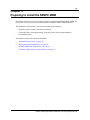
Chapter 3
Preparing to install the R2MFC MBM . . . . . . . . . . . . . . . . . . . . . . . . . . . . . . 27
Installation process map . . . . . . . . . . . . . . . . . . . . . . . . . . . . . . . . . . . . . . . . . . . . 28
Host system setup requirements . . . . . . . . . . . . . . . . . . . . . . . . . . . . . . . . . . . . . . 28
R2MFC MBM setup requirements . . . . . . . . . . . . . . . . . . . . . . . . . . . . . . . . . . . . . 29
Config DIP switches . . . . . . . . . . . . . . . . . . . . . . . . . . . . . . . . . . . . . . . . . . . . 29
MBM DIP switches . . . . . . . . . . . . . . . . . . . . . . . . . . . . . . . . . . . . . . . . . . . . . 29
Environment checklist . . . . . . . . . . . . . . . . . . . . . . . . . . . . . . . . . . . . . . . . . . . 30
Electrical requirements . . . . . . . . . . . . . . . . . . . . . . . . . . . . . . . . . . . . . . . . . . 30
Software requirements . . . . . . . . . . . . . . . . . . . . . . . . . . . . . . . . . . . . . . . . . . 30
Customer supplied hardware requirements . . . . . . . . . . . . . . . . . . . . . . . . . . . . . 30
Chapter 4
Installing the R2MFC MBM . . . . . . . . . . . . . . . . . . . . . . . . . . . . . . . . . . . . . . 31
Shutting down the system . . . . . . . . . . . . . . . . . . . . . . . . . . . . . . . . . . . . . . . . . . . . . . 32
Shutting down a BCM 4.0 system . . . . . . . . . . . . . . . . . . . . . . . . . . . . . . . . . . . . . 32
Shutting down the BCM 4.0 system software . . . . . . . . . . . . . . . . . . . . . . . . . 32
Shutting down the BCM 4.0 system hardware . . . . . . . . . . . . . . . . . . . . . . . . 33
Shutting down a BCM 3.7 or lower system . . . . . . . . . . . . . . . . . . . . . . . . . . . . . . 33
Installing an R2MFC MBM . . . . . . . . . . . . . . . . . . . . . . . . . . . . . . . . . . . . . . . . . . . . . . 34
Installing an R2MFC MBM in the BCM platform base chassis . . . . . . . . . . . . . . . 34
Installing an R2MFC MBM in the expansion unit . . . . . . . . . . . . . . . . . . . . . . . . . 35
Installing an R2MFC MBM in the BCM50 expansion unit . . . . . . . . . . . . . . . . . . . 36
Installing the rubber boot in an R2MFC module . . . . . . . . . . . . . . . . . . . . . . . . . . 36
Reconnecting the equipment . . . . . . . . . . . . . . . . . . . . . . . . . . . . . . . . . . . . . . . . 38
Removing an R2MFC MBM . . . . . . . . . . . . . . . . . . . . . . . . . . . . . . . . . . . . . . . . . . . . . 38
Removing an R2MFC MBM from the BCM platform base chassis . . . . . . . . . . . . 39
Removing an R2MFC MBM from the expansion unit . . . . . . . . . . . . . . . . . . . . . . 40
Wiring an R2MFC MBM . . . . . . . . . . . . . . . . . . . . . . . . . . . . . . . . . . . . . . . . . . . . . . . . 41
Connecting an R2MFC MBM to a service provider . . . . . . . . . . . . . . . . . . . . . . . . 43
Chapter 5
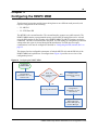
Configuring the R2MFC MBM . . . . . . . . . . . . . . . . . . . . . . . . . . . . . . . . . . . . 45
MFCR2 side (External Link) configurable parameters . . . . . . . . . . . . . . . . . . . . . . . . . 46
Physical line characteristics . . . . . . . . . . . . . . . . . . . . . . . . . . . . . . . . . . . . . . . . . 46
E1 framing . . . . . . . . . . . . . . . . . . . . . . . . . . . . . . . . . . . . . . . . . . . . . . . . . . . . . . . 46
Line signaling . . . . . . . . . . . . . . . . . . . . . . . . . . . . . . . . . . . . . . . . . . . . . . . . . . . . 47
Register signaling . . . . . . . . . . . . . . . . . . . . . . . . . . . . . . . . . . . . . . . . . . . . . . . . . 47
End of dialing (incoming) . . . . . . . . . . . . . . . . . . . . . . . . . . . . . . . . . . . . . . . . 48
End of dialing (outgoing) . . . . . . . . . . . . . . . . . . . . . . . . . . . . . . . . . . . . . . . . . 48
Disable ANI . . . . . . . . . . . . . . . . . . . . . . . . . . . . . . . . . . . . . . . . . . . . . . . . . . . 48
Default category . . . . . . . . . . . . . . . . . . . . . . . . . . . . . . . . . . . . . . . . . . . . . . . 49
Default subscriber status . . . . . . . . . . . . . . . . . . . . . . . . . . . . . . . . . . . . . . . . 49
NN40010-300
9
Configuring the MFCR2 (external) link . . . . . . . . . . . . . . . . . . . . . . . . . . . . . . . . . . . . 49
Setting Config DIP switches . . . . . . . . . . . . . . . . . . . . . . . . . . . . . . . . . . . . . . . . . 49
Creating a customized country code . . . . . . . . . . . . . . . . . . . . . . . . . . . . . . . . . . . 50
PRI side (Internal Link) configurable parameters . . . . . . . . . . . . . . . . . . . . . . . . . . . . 51
E1 Framing . . . . . . . . . . . . . . . . . . . . . . . . . . . . . . . . . . . . . . . . . . . . . . . . . . . . . . 51
Signaling . . . . . . . . . . . . . . . . . . . . . . . . . . . . . . . . . . . . . . . . . . . . . . . . . . . . . . . . 52
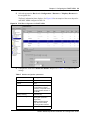
Configuring the PRI (internal) link . . . . . . . . . . . . . . . . . . . . . . . . . . . . . . . . . . . . . . . . 52
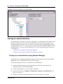
Configuring the PRI (internal) link using Element Manager . . . . . . . . . . . . . . . . . 52
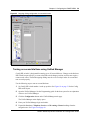
Configuring the PRI (internal) link using Unified Manager . . . . . . . . . . . . . . . . . . 54
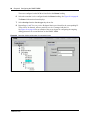
Turning on second dial tone . . . . . . . . . . . . . . . . . . . . . . . . . . . . . . . . . . . . . . . . . . . . 58
Turning on second dial tone using Element Manager . . . . . . . . . . . . . . . . . . . . . . 58
Turning on second dial tone using Unified Manager . . . . . . . . . . . . . . . . . . . . . . . 59
Chapter 6
R2MFC MBM maintenance . . . . . . . . . . . . . . . . . . . . . . . . . . . . . . . . . . . . . . 61
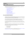
Inter-working functionality . . . . . . . . . . . . . . . . . . . . . . . . . . . . . . . . . . . . . . . . . . . . . . 61
Clock synchronization . . . . . . . . . . . . . . . . . . . . . . . . . . . . . . . . . . . . . . . . . . . . . . . . . 62
Diagnostic tools . . . . . . . . . . . . . . . . . . . . . . . . . . . . . . . . . . . . . . . . . . . . . . . . . . . . . . 63
Setting the R2MFC MBM to diagnostic mode . . . . . . . . . . . . . . . . . . . . . . . . . . . . 63
Alarms . . . . . . . . . . . . . . . . . . . . . . . . . . . . . . . . . . . . . . . . . . . . . . . . . . . . . . . . . . . . . 64
Alarms Measurements . . . . . . . . . . . . . . . . . . . . . . . . . . . . . . . . . . . . . . . . . . . . . 64
Group I errors . . . . . . . . . . . . . . . . . . . . . . . . . . . . . . . . . . . . . . . . . . . . . . . . . 64
Group II errors . . . . . . . . . . . . . . . . . . . . . . . . . . . . . . . . . . . . . . . . . . . . . . . . 65
Alarms propagation . . . . . . . . . . . . . . . . . . . . . . . . . . . . . . . . . . . . . . . . . . . . . . . . 65
Faceplate LEDs . . . . . . . . . . . . . . . . . . . . . . . . . . . . . . . . . . . . . . . . . . . . . . . . . . . . . . 66
Logs and traces . . . . . . . . . . . . . . . . . . . . . . . . . . . . . . . . . . . . . . . . . . . . . . . . . . . . . . 67
Error messages . . . . . . . . . . . . . . . . . . . . . . . . . . . . . . . . . . . . . . . . . . . . . . . . . . . . . . 67
Replacing an R2MFC MBM . . . . . . . . . . . . . . . . . . . . . . . . . . . . . . . . . . . . . . . . . . . . . 68
Upgrading firmware . . . . . . . . . . . . . . . . . . . . . . . . . . . . . . . . . . . . . . . . . . . . . . . . . . . 69
Chapter 7
Command Line Interface (CLI) . . . . . . . . . . . . . . . . . . . . . . . . . . . . . . . . . . . 73
Overview . . . . . . . . . . . . . . . . . . . . . . . . . . . . . . . . . . . . . . . . . . . . . . . . . . . . . . . . . . . 73
Users and passwords . . . . . . . . . . . . . . . . . . . . . . . . . . . . . . . . . . . . . . . . . . . . . . 73
Accessing the CLI . . . . . . . . . . . . . . . . . . . . . . . . . . . . . . . . . . . . . . . . . . . . . . . . . 74
LOad directory . . . . . . . . . . . . . . . . . . . . . . . . . . . . . . . . . . . . . . . . . . . . . . . . . . . . 75
INfo directory . . . . . . . . . . . . . . . . . . . . . . . . . . . . . . . . . . . . . . . . . . . . . . . . . . . . . 75
VIew directory . . . . . . . . . . . . . . . . . . . . . . . . . . . . . . . . . . . . . . . . . . . . . . . . . . . . 76
CNtrl directory . . . . . . . . . . . . . . . . . . . . . . . . . . . . . . . . . . . . . . . . . . . . . . . . . . . . 77
COnfig directory . . . . . . . . . . . . . . . . . . . . . . . . . . . . . . . . . . . . . . . . . . . . . . . . . . 79
ALarm directory . . . . . . . . . . . . . . . . . . . . . . . . . . . . . . . . . . . . . . . . . . . . . . . . . . . 81
SWerr directory . . . . . . . . . . . . . . . . . . . . . . . . . . . . . . . . . . . . . . . . . . . . . . . . . . . 83
MFC directory . . . . . . . . . . . . . . . . . . . . . . . . . . . . . . . . . . . . . . . . . . . . . . . . . . . . 84
R2MFC Media Bay Module Installation and Configuration Guide
10
R2 directory . . . . . . . . . . . . . . . . . . . . . . . . . . . . . . . . . . . . . . . . . . . . . . . . . . . . . . 87
PRI directory . . . . . . . . . . . . . . . . . . . . . . . . . . . . . . . . . . . . . . . . . . . . . . . . . . . . . 89
Appendix A
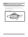
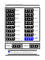
Configuring DIP switch settings and definitions . . . . . . . . . . . . . . . . . . . . 91
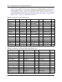
Country code defaults . . . . . . . . . . . . . . . . . . . . . . . . . . . . . . . . . . . . . . . . . . . . . . . . . 93
Mexico Config 1 . . . . . . . . . . . . . . . . . . . . . . . . . . . . . . . . . . . . . . . . . . . . . . . . . . 93
E1 physical characteristics . . . . . . . . . . . . . . . . . . . . . . . . . . . . . . . . . . . . . . . 93
E1 framing . . . . . . . . . . . . . . . . . . . . . . . . . . . . . . . . . . . . . . . . . . . . . . . . . . . 93
Register signaling . . . . . . . . . . . . . . . . . . . . . . . . . . . . . . . . . . . . . . . . . . . . . . 93
R2 line signaling . . . . . . . . . . . . . . . . . . . . . . . . . . . . . . . . . . . . . . . . . . . . . . . 93
MFC register signaling . . . . . . . . . . . . . . . . . . . . . . . . . . . . . . . . . . . . . . . . . . 94
Mexico Config 2 . . . . . . . . . . . . . . . . . . . . . . . . . . . . . . . . . . . . . . . . . . . . . . . . . . 95
E1 physical characteristics . . . . . . . . . . . . . . . . . . . . . . . . . . . . . . . . . . . . . . . 95
E1 framing . . . . . . . . . . . . . . . . . . . . . . . . . . . . . . . . . . . . . . . . . . . . . . . . . . . 95
Register signaling . . . . . . . . . . . . . . . . . . . . . . . . . . . . . . . . . . . . . . . . . . . . . . 95
R2 line signaling . . . . . . . . . . . . . . . . . . . . . . . . . . . . . . . . . . . . . . . . . . . . . . . 96
MFC register signaling . . . . . . . . . . . . . . . . . . . . . . . . . . . . . . . . . . . . . . . . . . 96
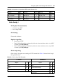
Brazil Config 1 . . . . . . . . . . . . . . . . . . . . . . . . . . . . . . . . . . . . . . . . . . . . . . . . . . . . 98
E1 physical characteristics . . . . . . . . . . . . . . . . . . . . . . . . . . . . . . . . . . . . . . . 98
E1 framing . . . . . . . . . . . . . . . . . . . . . . . . . . . . . . . . . . . . . . . . . . . . . . . . . . . 98
Register signaling . . . . . . . . . . . . . . . . . . . . . . . . . . . . . . . . . . . . . . . . . . . . . . 98
R2 line signaling . . . . . . . . . . . . . . . . . . . . . . . . . . . . . . . . . . . . . . . . . . . . . . . 98
MFC Register Signaling . . . . . . . . . . . . . . . . . . . . . . . . . . . . . . . . . . . . . . . . . 98
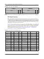
Brazil Config 2 . . . . . . . . . . . . . . . . . . . . . . . . . . . . . . . . . . . . . . . . . . . . . . . . . . . 100
E1 physical characteristics . . . . . . . . . . . . . . . . . . . . . . . . . . . . . . . . . . . . . . 100
E1 framing . . . . . . . . . . . . . . . . . . . . . . . . . . . . . . . . . . . . . . . . . . . . . . . . . . 100
Register signaling . . . . . . . . . . . . . . . . . . . . . . . . . . . . . . . . . . . . . . . . . . . . . 100
R2 line signaling . . . . . . . . . . . . . . . . . . . . . . . . . . . . . . . . . . . . . . . . . . . . . . 101
MFC Register Signaling . . . . . . . . . . . . . . . . . . . . . . . . . . . . . . . . . . . . . . . . 101
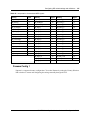
Argentina Config 1 . . . . . . . . . . . . . . . . . . . . . . . . . . . . . . . . . . . . . . . . . . . . . . . 102
E1 Physical Characteristics . . . . . . . . . . . . . . . . . . . . . . . . . . . . . . . . . . . . . 102
E1 Framing . . . . . . . . . . . . . . . . . . . . . . . . . . . . . . . . . . . . . . . . . . . . . . . . . . 103
Frame mode: Alternate . . . . . . . . . . . . . . . . . . . . . . . . . . . . . . . . . . . . . . . . . 103
Register signaling . . . . . . . . . . . . . . . . . . . . . . . . . . . . . . . . . . . . . . . . . . . . . 103
R2 Line Signaling . . . . . . . . . . . . . . . . . . . . . . . . . . . . . . . . . . . . . . . . . . . . . 103
MFC Register Signaling . . . . . . . . . . . . . . . . . . . . . . . . . . . . . . . . . . . . . . . . 103
Chile Config 1 . . . . . . . . . . . . . . . . . . . . . . . . . . . . . . . . . . . . . . . . . . . . . . . . . . . 105
E1 Physical Characteristics . . . . . . . . . . . . . . . . . . . . . . . . . . . . . . . . . . . . . 105
E1 Framing . . . . . . . . . . . . . . . . . . . . . . . . . . . . . . . . . . . . . . . . . . . . . . . . . . 105
Frame mode: Alternate . . . . . . . . . . . . . . . . . . . . . . . . . . . . . . . . . . . . . . . . . 105
Register signaling . . . . . . . . . . . . . . . . . . . . . . . . . . . . . . . . . . . . . . . . . . . . . 105
R2 line signaling . . . . . . . . . . . . . . . . . . . . . . . . . . . . . . . . . . . . . . . . . . . . . . 105
NN40010-300
11
MFC Register Signaling . . . . . . . . . . . . . . . . . . . . . . . . . . . . . . . . . . . . . . . . 106
Panama Config 1 . . . . . . . . . . . . . . . . . . . . . . . . . . . . . . . . . . . . . . . . . . . . . . . . 107
Appendix B
Diagnostic and loopback DIP switch settings. . . . . . . . . . . . . . . . . . . . . . 109
Appendix C
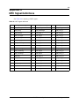
MFC Signal Definitions . . . . . . . . . . . . . . . . . . . . . . . . . . . . . . . . . . . . . . . . 111
Appendix D
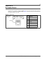
CLI Cable Pinout . . . . . . . . . . . . . . . . . . . . . . . . . . . . . . . . . . . . . . . . . . . . . 113
R2MFC Media Bay Module Installation and Configuration Guide
12
NN40010-300
13
How to Get Help
This section explains how to get help for Nortel products and services.
Getting Help from the Nortel Web site
The best way to get technical support for Nortel products is from the Nortel Technical Support
Web site:
http://www.nortel.com/support
This site provides quick access to software, documentation, bulletins, and tools to address issues
with Nortel products. More specifically, the site enables you to:
•
download software, documentation, and product bulletins
•
search the Technical Support Web site and the Nortel Knowledge Base for answers to
technical issues
•
sign up for automatic notification of new software and documentation for Nortel equipment
•
open and manage technical support cases
Getting Help over the phone from a Nortel Solutions Center
If you don’t find the information you require on the Nortel Technical Support Web site, and have a
Nortel support contract, you can also get help over the phone from a Nortel Solutions Center.
In North America, call 1-800-4NORTEL (1-800-466-7835).
Outside North America, go to the following Web site to obtain the phone number for your region:
http://www.nortel.com/callus
Getting Help from a specialist by using an Express Routing
Code
To access some Nortel Technical Solutions Centers, you can use an Express Routing Code (ERC)
to quickly route your call to a specialist in your Nortel product or service. To locate the ERC for
your product or service, go to:
http://www.nortel.com/erc
Getting Help through a Nortel distributor or reseller
If you purchased a service contract for your Nortel product from a distributor or authorized
reseller, contact the technical support staff for that distributor or reseller.
R2MFC Media Bay Module Installation and Configuration Guide
14 How to Get Help
NN40010-300
15
Chapter 1
Getting started
About this guide
This guide explains how to install, configure, and maintain the Nortel R2MFC Media Bay Module
(R2MFC MBM).
The guide also provides information about the Command Line Interface (CLI) tool used to
configure, operate, administer and maintain the R2MFC MBM from a computer.
Note: The CLI is separate from the Business Communications Manager
(BCM) system configuration tool.
The document contains the following chapters:
Chapter 2, “Overview” — introduces the elements of the R2MFC MBM.
Chapter 3, “Preparing to install the R2MFC MBM” — describes the process of preparing for
R2MFC MBM installation.
Chapter 4, “Installing the R2MFC MBM” — describes the process of installing the R2MFC
MBM and connecting the R2MFC MBM to the host system.
Chapter 5, “Configuring the R2MFC MBM” — describes the configuration tools and the process
of configuring the R2MFC MBM.
Chapter 6, “R2MFC MBM maintenance” — describes the maintenance tools and the process of
maintaining the R2MFC MBM.
Chapter 7, “Command Line Interface (CLI)” — describes the Command Line Interface and the
commands used to configure, operate, administer, and maintain the R2MFC MBM.
Audience
This guide is intended for BCM administrators who install MBMs.
R2MFC Media Bay Module Installation and Configuration Guide
16
Chapter 1 Getting started
Before you begin
This guide assumes the following:
•
•
•
•
The host system is installed and initialized and is working correctly.
The host system is running BCM 2.5 FP 1, or greater.
Users have a working knowledge of the host system operations.
All configuration installers have a working knowledge of the Windows operating system and
graphical user interfaces.
Acronyms
The following is a list of acronyms used in this guide.
Table 1 Acronyms
Acronym
Description
AIS
Alarm Indication Signal
ANI
Automatic Number Identification
BCM
Business Communication Manager
BPV
Bipolar Violations
CLI
Command Line Interface
CLID
Calling Line Identification
CO
Central Office
CRC4
Cyclic Redundancy Check 4
CSU
Channel Service Unit
DCH
D-Channel Handler
DTMF
Dual Tone Multi-Frequency
EEPROM
Electrically Erasable Prorammable Read Only Memory
ETSI
European Telecommunications Standards Institute
FBER
Frame Bit Error
FEBE
Far End Block Error
ISDN
Integrated Services Digital Network
LFA
Loss of Frame Alignment
LMA
Loss of Multiframe Alignment
LOS
Loss of Signal
MBM
Media Bay Module
MFC
Multi-Frequency Compelled
MSC
Media Services Card
OOF
Out-of-Frame
NN40010-300
Chapter 1 Getting started
17
Table 1 Acronyms (Continued)
Acronym
Description
OOM
Out of CRC-4 Multiframe Alignment
OOS
Out Of Service
PCM
Pulse Code Modulation
PRI
Primary Rate Interface
RAI
Remote Alarm Indication
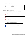
Symbols and text conventions
These symbols are used to Highlight critical information for the R2MFC MBM system:
Caution: Alerts you to conditions where you can damage the equipment.
Danger: Alerts you to conditions where you can get an electrical shock.
Warning: Alerts you to conditions where you can cause the system to fail or work
improperly.
Note: A Note alerts you to important information.
Tip: Alerts you to additional information that can help you perform a task.
R2MFC Media Bay Module Installation and Configuration Guide
18
Chapter 1 Getting started
!
Security note: Indicates a point of system security where a default should be changed,
or where the administrator needs to make a decision about the level of security required
for the system.
Warning: Alerts you to ground yourself with an antistatic grounding
strap before performing the maintenance procedure.
Warning: Alerts you to remove the R2MFC MBM main unit and
expansion unit power cords from the ac outlet before performing any
maintenance procedure.
These conventions and symbols are used to represent the Business Series Terminal display and.
Convention
Example
Used for
Word in a special font (shown in
the top line of the display)
Pswd:
Command line prompts on display telephones.
Underlined word in capital letters
(shown in the bottom line of a two
line display telephone)
PLAY
Display option. Available on two line display
telephones. Press the button directly below the
option on the display to proceed.
Dialpad buttons
£
Buttons you press on the dialpad to select a
particular option.
These text conventions are used in this guide to indicate the information described:
Convention
Description
bold Courier
text
Indicates command names and options and text that you need to enter.
Example: Use the info command.
Example: Enter show ip {alerts|routes}.
italic text
Indicates book titles
plain Courier
text
Indicates command syntax and system output (for example, prompts
and system messages).
Example: Set Trap Monitor Filters
FEATURE
HOLD
RELEASE
Indicates that you press the button with the coordinating icon on
whichever set you are using.
NN40010-300
Chapter 1 Getting started
19
Related publications
This section provides a list of additional documents referred to in this guide.
R2MFC Media Bay Module Installation and Configuration Guide
20
Chapter 1 Getting started
NN40010-300
21
Chapter 2
Overview
This chapter provides an overview of the R2MFC Media Bay Module (R2MFC MBM).
This chapter includes the following information:
•
•
•
•
“General information”
“Administration and maintenance tools” on page 22
“R2MFC MBM faceplate elements” on page 22
“R2MFC MBM back and underside elements” on page 24
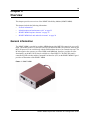
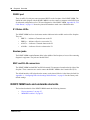
General information
The R2MFC MBM is a media bay module (MBM) that provides MFC-R2 connectivity over an E1
trunk. The module works as a converter between Euro-ISDN and MFC-R2 protocols, allowing the
MFC-R2 protocol E1 to work directly with the BCM without the use of an external converter. The
BCM recognizes the converter as a Euro-ISDN trunk MBM and, therefore, provides all of the
functionality on the MFC-R2 E1 that is available on a Euro-ISDN E1. The MFC-R2 trunk is
controlled by DIP switches and the Command Line Interface (CLI) on the R2MFC MBM. Figure 1
provides an illustration of the R2MFC MBM.
Figure 1 R2MFC MBM
R2MFC Media Bay Module Installation and Configuration Guide
22
Chapter 2 Overview
Administration and maintenance tools
R2MFC MBM configuration involves the following:
•
•
Internal link configuration for the PRI internal link to the BCM. The internal link uses preset
characteristics and therefore does not require localization.
External link configuration of the MFC-R2 E1 the external interface to public network. The
external link allows for localization in different countries.
External link configuration is performed using the DIP switches on the front of the R2MFC MBM
or by using the CLI, which is accessed through a serial port on the faceplate of the R2MFC MBM.
Internal link configuration is performed using either Element Manager or Unified Manager. Refer
to “Configuring the R2MFC MBM” on page 45 for information on how to use the configuration
tools.
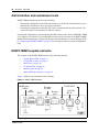
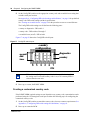
R2MFC MBM faceplate elements
The faceplate of the R2MFC MBM consists of the following elements:
•
•
•
•
•
•
“System Status LEDs” on page 23
“Config DIP switches” on page 23
“RS232 port” on page 24
“E1 Status LEDs” on page 24
“Bantam jacks” on page 24
“BNC and RJ-48 connectors” on page 24
Figure 2 illustrates the placement of these elements.
Figure 2 R2MFC MBM faceplate
MBM status
3 LEDS
DIP
switches
NN40010-300
75 Ω E1 BNC
E1 status
4 LEDS
RJ-45
Bantam
jacks
120 Ω E1
RJ-48
Chapter 2 Overview
23
System Status LEDs
The R2MFC MBM has three visual status monitor indicators on the left side of the faceplate. They
are:
•
•
•
Power LED — This green LED indicates the status of power to the R2MFC MBM.
In Service LED — This green LED indicates the status of the E1 signal coming to the
R2MFC MBM from the BCM.
Diag LED — This red LED indicates if the R2MFC MBM is in a diagnostic or loopback
mode.
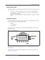
Config DIP switches
The R2MFC MBM has six config DIP switches on its faceplate. These DIP switches are used to
set the following configurations for the R2MFC MBM:
•
•
•
country
problem diagnosis
second dial tone
DIP switches must be set before power is connected to the R2MFC MBM. Figure 3 shows the
Config DIP switches.
Figure 3 Config DIP Switches
country
configuration
diagnostics
O
N
1
2
3
4
5
6
second
dial
tone
country
6 5 4 3 2 1
ON
For DIP switch values and configuration information, see “Configuring the MFCR2 (external)
link” on page 49.
These DIP switches are also used for problem diagnostics. For specific settings and uses, see
“Diagnostic tools” on page 63.
R2MFC Media Bay Module Installation and Configuration Guide
24
Chapter 2 Overview
RS232 port
There is an RJ-45 serial port connector named RS232 on the faceplate of the R2MFC MBM. The
N0026100 cable, shipped with the R2MFC MBM, is used to connect a computer to the RS232 port
for advanced configuration or for CLI-based diagnostics of the R2MFC MBM. Appendix D, “CLI
Cable Pinout,” on page 113 shows the pinout information to make a new N0026100 cable.
E1 Status LEDs
The R2MFC MBM has four visual status monitor indicators in the middle section of the faceplate.
They are:
•
•
•
•
ERR Tx — indicates a Transmit error on the E1
ERR Rx — indicates a Receive error on the E1
ALM Tx — indicates a Transmit alarm on the E1
ALM Rx — indicates a Receive alarm on the E1
Bantam jacks
The R2MFC MBM contains Bantam Jacks in the middle of the faceplate, to be used for connecting
diagnostic equipment. The jacks are labeled DIAG.
BNC and RJ-48 connectors
The R2MFC MBM has both BNC and RJ-48 external E1 connectors located on the far right of the
faceplate. These connectors are used to connect the R2MFC MBM to the Central Office (CO).
The default interface will be based on the country code selected. Mexico is the factory default. See
Appendix A, “Configuring DIP switch settings and definitions,” on page 91 for the country code
default settings.
R2MFC MBM back and underside elements
The back and underside of the R2MFC MBM contain the following elements:
•
•
NN40010-300
“Power connectors” on page 25
“MBM DIP switches” on page 25
Chapter 2 Overview
25
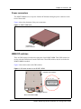
Power connectors
The R2MFC MBM receives its power from the BCM chassis through a power connector on the
back of the module.
Figure 4 shows the placement of the power connectors.
Figure 4 R2MFC MBM back
DS256 and
power connector
MBM DIP switches
There are DIP switches located on the underside of the R2MFC MBM. These DIP switches are
used to select the DS30 buses from the DS256 bus. These DIP switches must be set before the
R2MFC MBM is installed.
Figure 5 shows the location of the DIP switches.
Figure 5 DIP switch location on the R2MFC MBM
Underside of the R2MFC
6 5 4 3 2 1
Off
On
DIP switches
Back of the R2MFC MBM
R2MFC Media Bay Module Installation and Configuration Guide
26
Chapter 2 Overview
NN40010-300
27
Chapter 3
Preparing to install the R2MFC MBM
This chapter provides an overview of the preparation required to install the R2MFC MBM in a
host system. (The host system is the BCM system to which the R2MFC MBM connects.)
The information in this chapter is based on the following assumptions:
•
The host system is installed, initialized, and tested.
•
The installer has a working knowledge of the host system and an understanding of
telecommunications.
This chapter contains the following information:
•
“Installation process map” on page 28
•
“Host system setup requirements” on page 28
•
“R2MFC MBM setup requirements” on page 29
•
“Customer supplied hardware requirements” on page 30
R2MFC Media Bay Module Installation and Configuration Guide
28 Chapter 3 Preparing to install the R2MFC MBM
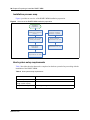
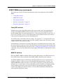
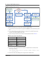
Installation process map
Figure 6 provides an overview of the R2MFC MBM installation preparation.
Figure 6 Overview of the R2MFC MBM installation preparation
Installation
preparation
Ensure that BCM is
installed and configured
properly
Ensure that all of the
customer supplied
hardware is present
Determine the correct
country and variant
Ensure electrical
requirements are met
Determine the correct
DS30 setting
information
Ensure software
requirements are met
Ensure environmental
requirements are met
Host system setup requirements
Table 2 describes the tasks that must be completed on the host system before proceeding with the
installation of the R2MFC MBM.
Table 2 Host system setup requirements
Task
Location of task information
Install host system
BCM: Installation and Maintenance Guides
Determine if host system has
enough system capacity
BCM: Installation and Maintenance Guides
Configure E1 Settings
BCM: Programming Guide
NN40010-300
Chapter 3 Preparing to install the R2MFC MBM 29
R2MFC MBM setup requirements
This section provides the following information about the setup requirements for the R2MFC
MBM:
•
“Config DIP switches”
•
“MBM DIP switches”
•
“Environment checklist”
•
“Software requirements” on page 30
•
“Electrical requirements” on page 30
Config DIP switches
Determine and set the Config DIP switches to the correct country code, and second dial tone
setting for the R2MFC MBM. Predefined country codes are set by the Config DIP switches.
Special configurations are set through the CLI. See “Configuring the MFCR2 (external) link” on
page 49 for a procedure on how to set the DIP switches for a predefined country code or how to
create a special configuration to meet the installation needs.
The default country code setting is Mexico config 1. See Appendix A, “Configuring DIP switch
settings and definitions,” on page 91 for a list of the available country codes, the country default
settings, and the second dial tone settings.
Second dial tone, when turned on, generates and supplies a second dial tone to the end user, after
the end user dials the trunk access code. The end user hears a dial tone between the last digit of the
access code, indicating that a line was accessed. See “Turning on second dial tone” on page 58 for
a procedure on how to set the DIP switches, and configure the BCM for second dial tone to work
properly.
MBM DIP switches
Before the R2MFC MBM is installed, DS30 buses and offsets must be set by DIP switches. Use
the six DIP switches on the underside of the R2MFC MBM, behind the power connector.
The R2MFC MBM occupies two DS30 buses from the DS256 bus; however, only the first is
actually used. Buses 1 and 8 are reserved for internal BCM communications. Therefore, the
R2MFC MBM DIP switches can only be set to use buses 2 through 6 on a 2/6 split or buses 2
through 5 on a 3/5 split. If there are not enough DS30 resources available, an expansion module
can be installed to provide the extra resources required. For information about setting DIP
switches and installing an expansion module, refer to the BCM Installation and Maintenance
guides supplied with the host system.
R2MFC Media Bay Module Installation and Configuration Guide
30 Chapter 3 Preparing to install the R2MFC MBM
Environment checklist
The R2MFC MBM environmental requirements are covered by the host system environment
setup. See the BCM Installation and Maintenance guide supplied with the host system for details
of environmental requirements.
Electrical requirements
The R2MFC MBM power is supplied through the chassis on the host sytem. See the BCM
Installation and Maintenance guide supplied with the host system for details of the electrical
requirements.
Software requirements
R2MFC MBM firmware upgrades will be posted at www.nortel.com under Support & Training >
Technical Support > Software Downloads. Access this web site to see if there is a newer version
of firmware available than the firmware shipped on the R2MFC MBM. See “Upgrading firmware”
on page 69 for information on how to upgrade to the latest release of firmware.
Customer supplied hardware requirements
The following equipment is required to install of the R2MFC MBM:
•
Computer with monitor and serial port for access to the CLI.
•
E1 connection from local telephony service provider. Full description of the signaling
provided over the E1 by the CO.
NN40010-300
31
Chapter 4
Installing the R2MFC MBM
This chapters describes how to install and remove an R2MFC MBM in a host BCM system.
This chapter provides the following installation and removal procedures:
•
•
•
•
“Shutting down the system”
“Installing an R2MFC MBM” on page 34
“Removing an R2MFC MBM” on page 38
“Wiring an R2MFC MBM” on page 41
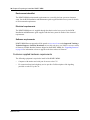
Figure 7 provides an overview of the steps for installing the R2MFC MBM.
Figure 7 Overview of the R2MFC MBM installation
Set module DIP
switches
Shut down the BCM
Replace bezel
NO
Disconnect cables and
power from both units
Remove front bezel
from the expansion unit
to eject blank filler on
MBM
Install new module
Restore power to BCM
and expansion unit
Reconnect all cables
Monitor LEDs for power
and status
Is this
installation part
of a new system
installation?
YES
Use Element Manager
or Unified Manager
to identify the module
to the system
Continue with
system
initialization
R2MFC Media Bay Module Installation and Configuration Guide
32 Chapter 4 Installing the R2MFC MBM
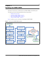
Shutting down the system
Before you shut down the system or perform any maintenance procedures, read the following
warnings to ensure you and your system are properly protected.
Warning: If you are installing a new BCM or an expansion unit, refer to the
Installation and Maintenance guide for the host system for instructions about installing
a new system before you connect the system to the AC power outlet.
Warning: Failure to follow procedures to properly disconnect the BCM and
expansion unit can result in module or system damage.
Warning: Ensure you are properly grounded before handling modules or any
components that are part of the BCM hardware.
How you shut down your system depends on the version of BCM system you are running. Use one
of the following procedures to shutdown your BCM system in preparation for installing the
R2MFC MBM.
•
Shutting down a BCM 4.0 system
•
“Shutting down a BCM 3.7 or lower system” on page 33
Shutting down a BCM 4.0 system
Shutting down a BCM 4.0 system is a two step process. First you must shut down the system
software, then you must shut down the system hardware.
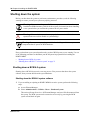
Shutting down the BCM 4.0 system software
1
If you are adding or replacing an R2MFC MBM in an active system, perform the following
steps:
a
Access Element Manager.
b
Select Administrations > Utilities > Reset > Shutdown System.
This action will stop all services. All Element Manager sessions will be disconnected from
the system. The BCM system can be restored to service only by powering the BCM
system off and back on again.
NN40010-300
Chapter 4 Installing the R2MFC MBM 33
c
Click Ok.
The progress update dialog box appears and the BCM system begins the shutdown
process. When the shutdown process is complete, the final warning dialog box appears,
and the LEDs enter the flashing state.
d
Click Ok to disconnect Element Manager.
When the shutdown Element Manager is disconnected, the system gives an audible beep.
The LEDs remain in the flashing state until the hardware is shutdown (see “Shutting down
the BCM 4.0 system hardware” on page 33).
If the system hardware is not shutdown within about 15 minutes, it automatically boots up
again.
Shutting down the BCM 4.0 system hardware
Warning: Remove all of the connections to the BCM system before you
power down the system.
Failure to disconnect lines before you power down the system can cause
damage to the system.
1
Remove the DS256 cables from the front of the BCM main unit and, if present, the expansion
unit. This includes the data connections on the MSC.
Mark the cables to ensure correct reconnection.
Warning: You must disconnect power from the main unit after you
have performed an Element Manager shutdown. The main unit cannot
start operating again until after power has been disconnected and then
reconnected.
2
Turn off the power switch located on the BCM main unit and expansion unit.
3
Disconnect the BCM main unit and expansion unit power cords from the AC outlet.
4
Ensure you have room to access the part you are working on. Remove the BCM main unit
from the rack, if necessary.
Shutting down a BCM 3.7 or lower system
1
If you are adding or replacing an R2MFC MBM in an active system, perform the following
steps:
a
Access the Unified Manager.
b
Choose System.
c
Select the Logoff menu and then click Shutdown.
d
Click Yes.
R2MFC Media Bay Module Installation and Configuration Guide
34 Chapter 4 Installing the R2MFC MBM
e
Wait until the Status changes to Complete! It is safe to turn off the system.
f
Click Done.
g
Exit the Unified Manager.
2
Attach one end of the grounding strap to your wrist and the other end to a grounded metal
surface.
3
Ensure the cables connected to the front of the BCM and the expansion unit are clearly marked
as to how they are connected.
4
Disconnect the BCM and expansion unit power cords from the AC outlet.
5
Remove the cables from all the R2MFC MBMs and the media services card (MSC) on the
BCM base function tray and the expansion unit (if attached).
Installing an R2MFC MBM
Follow the procedures in this section to install an R2MFC MBM in a BCM platform base chassis
or expansion unit.
Installing an R2MFC MBM in the BCM platform base chassis
Perform the following steps to install an R2MFC MBM in the BCM platform base chassis:
Caution: Only install the R2MFC MBM when the system is powered down. See
“Shutting down the system” on page 32.
1
Ensure that both the faceplate and underside DIP switches on the R2MFC MBM are set
correctly. For information on how to set the faceplate switches, refer to “Setting Config DIP
switches” on page 49. For information about how to set the underside switches, refer to the
Installation and Maintenance guide for the host BCM.
2
Select an open media bay.
3
With the face of the R2MFC MBM facing toward you, insert the R2MFC MBM into the open
bay.
4
Push the R2MFC MBM completely into the unit. You will hear a click when the module is
firmly seated in the media bay.
NN40010-300
Chapter 4 Installing the R2MFC MBM 35
Installing an R2MFC MBM in the expansion unit
Perform the following steps to install an R2MFC MBM in the BCM expansion unit chassis. Install
the R2MFC MBM when the system is powered down:
Caution: Only install the R2MFC MBM when the system is powered down. See
“Shutting down the system” on page 32.
Warning: Failure to follow procedures to properly disconnect the BCM and
expansion unit can result in module or system damage.
1
Ensure that both the faceplate and underside DIP switches on the R2MFC MBM are set
correctly. For information on how to set the faceplate switches, refer to “Setting Config DIP
switches” on page 49. For information about how to set the underside switches, refer to the
BCM Installation and Maintenance guide for the host system.
2
Remove the front bezel from the expansion unit.
3
Select an open media bay.
4
With the faceplate of the R2MFC MBM facing toward you, insert the R2MFC MBM into the
open bay. Ensure that any cables at the rear of the module are clear of the platform base
chassis.
5
Push the R2MFC MBM into the unit. You will hear a click when the module is firmly seated in
the media bay.
6
Install the front bezel on the expansion unit.
R2MFC Media Bay Module Installation and Configuration Guide
36 Chapter 4 Installing the R2MFC MBM
Installing an R2MFC MBM in the BCM50 expansion unit
Perform the following steps to install an R2MFC MBM in the BCM50 expansion unit chassis.
Install the R2MFC MBM when the system is powered down:
Caution: Only install the R2MFC MBM when the system is powered down. See
“Shutting down the system” on page 32.
Warning: Failure to follow procedures to properly disconnect the BCM and
expansion unit can result in module or system damage.
1
Ensure that both the faceplate and underside DIP switches on the R2MFC MBM are set
correctly. For information on how to set the faceplate switches, refer to “Setting Config DIP
switches” on page 49. For information about how to set the underside switches, refer to the
BCM Installation and Maintenance guide for the host system.
2
With the faceplate of the R2MFC MBM facing toward you, insert the R2MFC MBM into the
open bay. Ensure that any cables at the rear of the module are clear of the platform base
chassis.
3
Push the R2MFC MBM into the unit. You will hear a click when the module is firmly seated in
the media bay.
Installing the rubber boot in an R2MFC module
Perform the following steps to install the rubber boot onto an R2MFC transmit or receive co-axial
cable.
NN40010-300
Chapter 4 Installing the R2MFC MBM 37
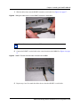
1
Slide the rubber boot onto the R2MFC transmit co-axial cable. See Figure 8 on page 37.
Figure 8 Sliding the rubber boot on to the R2MFC transmit co-axial cable
Note: Rubber boots ensure that no ESD occurs on to the co-axial connectors.
2
Connect the R2MFC co-axial cable to the correct location on the MBM. See Figure 9 on page
37.
Figure 9 R2MFC Transmit Co-axial cable connected to the MBM
3
Repeat steps 1 and 2 to attach the rubber boot to the other R2MFC co-axial cable.
R2MFC Media Bay Module Installation and Configuration Guide
38 Chapter 4 Installing the R2MFC MBM
Reconnecting the equipment
After you install the module correctly into the bay, you must return the equipment to operation.
Caution: Complete the following steps carefully to ensure you return your
system to operation without endangering the equipment or yourself.
1
Plug the power cords for the BCM and any expansion units back into the AC outlets.
Note: The Business Communications Manager system starts up when you
connect the AC power cord. System startup takes several minutes to complete.
2
Connect the cables to the proper outlets on the R2MFC MBM and the MSC on the BCM.
3
Check that the LEDs on the newly installed R2MFC MBM are on and indicating the correct
state. Refer to “Faceplate LEDs” on page 66 for a detailed description of the LED states.
4
Confirm that the BCM is functioning properly by testing to make sure it works the same as it
did before installing the R2MFC MBM.
5
Configure the module. Refer to Chapter 5, “Configuring the R2MFC MBM,” on page 45 for
details.
Removing an R2MFC MBM
Follow the procedures in this section to remove an R2MFC MBM from a BCM platform base
chassis or expansion unit.
Figure 10 provides an overview of the process for removing an R2MFC MBM.
Figure 10 Overview of removing an R2MFC MBM
Shut down BCM and
expansion unit
Disconnect power from
both units
Remove module cables
Remove module
NN40010-300
Chapter 4 Installing the R2MFC MBM 39
Removing an R2MFC MBM from the BCM platform base chassis
Perform the following steps to remove an R2MFC MBM from the BCM platform base chassis.
Remove the R2MFC MBMs after the system is powered down.
1 Power-down the BCM system (see “Shutting down the system” on page 32).
2
Remove any cabling from the R2MFC MBM faceplate.
3
Grasp the right edge of the MBM ejector lever with your thumb, index, and middle fingers.
Pull outward to partially eject the R2MFC MBM. Pull further on the lever to eject the R2MFC
MBM from the bay. Figure 11 on page 39 shows how to remove a BCM 200 R2MFC MBM.
Figure 12 on page 40 shows how to remove a BCM 400 R2MFC MBM.
4
Grasp the top and bottom edges of the R2MFC MBM. Remove the R2MFC MBM from the
BCM platform base chassis MBM bay (see Figure 11 on page 39 and Figure 12 on page 40).
Place the R2MFC MBM in a clean, safe, and static-free area.
Figure 11 How to remove a BCM200 R2MFC MBM
Grasp the edge
of the R2MFC
MBM ejector lever and pull out.
R2MFC Media Bay Module Installation and Configuration Guide
40 Chapter 4 Installing the R2MFC MBM
Figure 12 How to remove a BCM400 R2MFC MBM
Grasp the edge of the
R2MFC MBM ejector lever
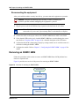
Removing an R2MFC MBM from the expansion unit
Use this procedure to remove an R2MFC MBM from the BCM expansion unit.
Warning: Remove the R2MFC MBM after the system is powered down.
1
Power-down the BCM expansion unit system (see “Shutting down the system” on page 32).
2
Remove any cabling from the R2MFC MBM faceplate.
3
Remove the expansion unit front bezel.
4
Grasp the edge of the MBM ejector lever. Pull outward to eject the R2MFC MBM. Refer to
Figure 13.
NN40010-300
Chapter 4 Installing the R2MFC MBM 41
Figure 13 How to remove the expansion unit front bezel
BCM expansion unit
1. Push against the bottom
2. Pull out from the top
MBM latches
5
Grasp the top and bottom edges of the R2MFC MBM. Remove the R2MFC MBM from the
BCM expansion unit. Place the R2MFC MBM in a clean, safe, and static-free area.
Wiring an R2MFC MBM
This section describes how to wire the cables that connect to the R2MFC MBM. The R2MFC
MBM is connected to the CO by either RJ48C or BNC connectors. The BNC connector is the
default interface. The default connector can be changed either by setting the country - selection
DIP switches or by creating a custom country code profile through the CLI. See “Configuring the
MFCR2 (external) link” on page 49 for information on how to change the active interface.
If the 75 Ω BNC connector pair is used, two coax cables are required for transmit and receive.
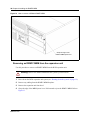
If the 120 Ω RJ-48 connector is used, the cable pinout must be set up as follows:
Figure 14 R2MFC MBM RJ48 wiring array
R2MFC MBM
connector
To network
To plug
Receive from
network
1- Rtip
2 - Rring
3 - Rshield
Transmit to network
4-Ttip
5-Tring
6-Tshield
RJ48 jack
R2MFC Media Bay Module Installation and Configuration Guide
42 Chapter 4 Installing the R2MFC MBM
Warning: Only allow qualified persons to service the BCM system.
The installation and service of this unit must be performed by service personnel with the
appropriate training and experience. Service personnel must be aware of the hazards of
working with telephony equipment and wiring. They must have experience in techniques
that minimize any danger of shock or equipment damage.
Warning: Leakage currents
Service personnel must be alert to the possibility of high-leakage currents becoming
available on metal system surfaces during power line fault events on network lines. These
leakage currents normally safely flow to Protective Earth ground through the power cord.
However, if the AC power is unplugged prior to disconnecting the cables from the front of
the base function tray, high-leakage currents available on metal system surfaces can occur.
System shutdown: You must disconnect the R2MFC MBM cables from the system before
disconnecting the power cord from a grounded outlet.
System startup: You must reconnect the power cords to a grounded outlet before
reconnecting the cables to an R2MFC MBM.
Danger: Electrical shock hazards
Electrical shock hazards from the telecommunications network and AC mains are possible
with this equipment. To minimize risk to service personnel and users, the BCM system
must be connected to an outlet with a third-wire ground. In addition, all unused slots must
have blank faceplates installed. The covers on all units must be in place at the completion
of any servicing.
Figure 15 on page 43 provides an overview of the process for connecting trunk wiring to the BCM
R2MFC MBMs.
NN40010-300
Chapter 4 Installing the R2MFC MBM 43
Figure 15 Trunk wiring overview
Install R2MCF MBM
Read warnings
Connect cables to
appropriate trunk
modules
Determine the correct
connector to use
Continue with setup
procedures
Connecting an R2MFC MBM to a service provider
Warning: Electrical shock warning.
The Business Communications Manager R2MFC MBMs have been safety-approved for
installation into BCM base units and expansion units. Both the installer and user are
responsible to ensure that installation of the Business Communications Manager hardware
does not compromise existing Safety approvals.
BEFORE YOU OPEN the Business Communications Manager base unit or Business
Communications Manager expansion unit, ensure that the network telecom cables are
unplugged, and that the unit is then disconnected from the ac power source.
Station modules: The ports on these modules are meant to be connected only to approved
digital telephones and peripherals, with the proper cables, on a protected internal wiring
system.
Do not connect any telephones to wiring that runs outside the building.
Read and follow the installation instructions carefully.
Perform the following steps to connect an R2MFC MBM to the network:
1
Determine the connector type to be used, either RJ48C or BNC connectors.
2
Locate the appropriate connector on the front of the module.
R2MFC Media Bay Module Installation and Configuration Guide
44 Chapter 4 Installing the R2MFC MBM
3
Attach the transmit BNC cable to the connector labeled Tx and the receive BNC cable to the
connector labeled Rx, for countries using BNC connections. Insert the connector into the RJ48
jack on the module, for countries using the RJ48 connections. Figure 14 on page 41 shows the
wiring pinouts for an R2MFC MBM to connect to a service provider using RJ48 connectors.
Warning: If you are using a service provider channel service unit (CSU), you must
disable the Business Communications Manager system internal CSU by using Business
Communications Manager Unified Manager. For more information, refer to the
Programming Operations guide for the host system.
4
Use the Element Manager to configure the lines or sets associated with the module. Refer to
the BCM Programming Operations guide for the host system for more information.
Refer to the BCM Programming Operations guide for the host system for information on
changing the default settings for each line/loop.
NN40010-300
45
Chapter 5
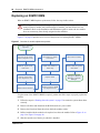
Configuring the R2MFC MBM
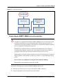
Trunk protocol conversion provides interworking between two different trunk protocols, and
requires configuration for the following:
•
•
E1- MFCR2
E1- ETSI Euro-PRI
The MFCR2 is the external interface. The external interface connects to a public network. The
R2MFC MBM contains preprogrammed country-specific MFCR2 settings that can be selected
using the DIP switches on the faceplate of the R2MFC MBM. The MFCR2 settings can also be
customized. The PRI is an internal link to the BCM. The PRI setting are configured to predefined
settings when the region is selected during BCM initialization. The PRI does not require
customization, but it must be configured as detailed in “Configuring the PRI (internal) link” on
page 52.
This chapter lists the configurable parameters of both the MFCR2 side and the PRI side of the
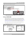
R2MFC MBM, and explains how to configure them. Figure 16 provides an overview of the
configuration process.
Figure 16 Configuring the R2MFC MBM
Install the
R2MFC MBM
Determine the correct
configuration
parameters for the
external link
Does the
setup require custom
settings?
YES
Create a new
customized country
code
NO
Set Config DIP switches
Determine the correct
configuration
parameters for the
internal link
Configure the internal
PRI link through
Element Manager or
Unified Manager
R2MFC Media Bay Module Installation and Configuration Guide
46
Chapter 5 Configuring the R2MFC MBM
MFCR2 side (External Link) configurable parameters
Physical line characteristics
The MBM has two options for physical connections on the faceplate:
1
RJ-48 connector for twisted pair cable (line impedance of 120 Ohms)
2
a pair of BNC connectors for coax cables (line impedance of 75 Ohms)
The BNC connectors can have one of the following:
•
•
TX shielding connected to ground (default)
RX and TX shielding not connected to ground
Only one of the two connector types can be active. The default active interface is the BNC
connector. The BCN connector is part of the country-specific defaults for Mexico. Each of the
country codes activates the appropriate connector, based on the country standard for connectors.
The active interface can be customized in the firmware through the CLI by using commands in the
COnfig directory.
E1 framing
The external link uses Channel Associated Signaling on timeslot 16, therefore; TS16 multiframe
format is always used. In addition, optional CRC4 multiframe can be used (for monitoring digital
transmission quality), instead of basic “alternate frame” format.
The CRC4 multiframe option is activated by the firmware as part of the country-specific defaults.
PCM coding is A-law.
These settings can be customized in the firmware through the CLI by using commands in the
ALarm directory.
Note: Changes made to the framing parameters must be configured in both the R2MFC
MBM and the BCM.
NN40010-300
Chapter 5 Configuring the R2MFC MBM
47
Line signaling
Line signaling (for example, seize, answer, and disconnect) are implemented by R2 Channel
Associated Signaling known as ABCD bits. Only the two bits AB are used for line signaling. The
state (value) of the bits indicate the signal.
The channels are always bidirectional, (that is, they accept incoming calls or originate outgoing
calls). The channel behavior also supports one-way trunks. The direction of the signal does not
need to be configured. Because the R2MFC MBM is passive, the R2MFC MBM does not initiate
calls; it only passes call origination attempts from one side to the other. The R2MFC MBM
assumes that the two sides (BCM and CO) respect the direction of the trunk as agreed between
them.
The meaning of the bit states are part of the country-specific parameters; however, they can be
customized through the CLI by using commands in the R2 directory.
The following are additional options included in country-specific parameters:
•
•
•
use backward force-release signal to clear back (yes/no)
release-guard state (timer) when clearing back (timer value)
optional CD bits value (usually ignored)
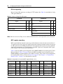
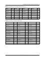
Register signaling
Register signaling (digits transmission) is implemented by in-band dual-tone signals known as
MFC-R2. Physically, there are 15 forward signals and 15 backward signals. The standard defines
two stages of the signaling. The meaning of the signal depends on the stage and the direction of the
call. In total, there are four tables of 15 signals each. See Appendix A, “Configuring DIP switch
settings and definitions,” on page 91 for MFC country-specific signal tables.
The meaning of MFC signals can be different when transmitted or received. MFC signal tables are
part of the country-specific parameters. The meaning of the MFC signals in the R2MFC MBM are
configurable through the CLI by using commands in the MFC directory.
The following are other options included in country-specific parameters:
R2MFC Media Bay Module Installation and Configuration Guide
48
Chapter 5 Configuring the R2MFC MBM
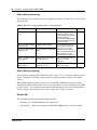
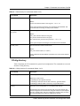
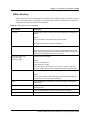
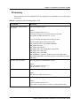
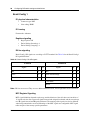
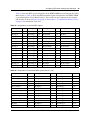
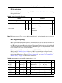
End of dialing (incoming)
End of dialing for an incoming call can be configured by using the CLI. See Table 3, for the end of
dialing options.
Table 3 Minimum (or fixed) number length + timer parameters
Option
Parameters
Meaning
Default
Explicit ‘End of dial’ signal
(I-15)
None
Yes
The preset option for all
countries. However, signal
has low significance, because
the end of dialing is
determined by the BCM (PRI
side) when it receives the last
digit of the number.
Minimum (or fixed) number
length and timer
Minimal number of digits
Minimum (or fixed) number
length and timer
Optional number of additional
digits
Receiving minimum number of No
digits + optional number of
digits means end of dial
No
(maximum length reached)
When a fixed length number is
always expected, set the
optional number of digits to 0.
Minimum (or fixed) number
length and timer
Interdigit timer in the minimal
interval (long timer)
Expiry of the long timer means No
MFC error - number
incomplete.
Minimum (or fixed) number
length and timer
Interdigit timer in the optional
interval (short timer)
Expiry of the short timer
means end of dial.
No
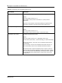
End of dialing (outgoing)
End of dialing in outgoing calls is indicated by MFC signal “I15” (or equivalent country-specific
signal). This signal is sent if the far-end requests next digit beyond the last digit of the dialed
number.
When R2MFC MBM originates a call to the CO, the R2MFC MBM has already received the
whole dialed number from the BCM. This is because the digits are passed from BCM to the MBM
by PRI “en-bloc.” This operation mode means that BCM determines user end-of-dialing either by
number of digits, explicit input from user (for example, the “#” digit), or timeout.
Disable ANI
The ANI request option can be disabled. When disabled:
•
•
Incoming call — R2MFC MBM does not request ANI.
Outgoing call — When far end requests ANI, R2MFC MBM answers “ANI not available.”
NN40010-300
Chapter 5 Configuring the R2MFC MBM
49
Default category
The MFC subscriber category, sent by R2MFC MBM in outgoing calls, is fixed. The default
category for all countries is II1 (subscriber without priority). If needed, the default can be changed
by CLI.
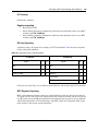
Default subscriber status
The user can set default subscriber status (for example, free, busy, and vacant number) for
incoming calls. When this feature is enabled, the R2MFC MBM in an incoming call sends the
preset default subscriber status, instead of the status received from the PRI status.
The subscriber status option is not enabled in R2MFC MBM; therefore, the subscriber status is
translated from ISDN message to MFC, and vice versa.
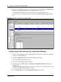
Configuring the MFCR2 (external) link
The MFCR2 (external) link is configured directly on the R2MFC MBM by setting DIP switches,
and using a CLI on the R2MFC MBM. Standard predefined configurations already exist, and must
be used, whenever possible. Country code configurations set, by DIP switches, are hard-coded,
and can be changed only by using the CLI. See “Setting Config DIP switches” for a description of
how to set the predefined country code and second dial tone settings. The CLI can be used to
create a customized country codes. See “Creating a customized country code” on page 50 for a
procedure on how to create the customized country code.
Setting Config DIP switches
The Config DIP switch settings include diagnostic mode, country codes, and second dial tone.
Country codes include the default settings for the connection (link) for the country selected. See
Appendix A, “Configuring DIP switch settings and definitions,” on page 91 for the country code
DIP switch settings and their specifications.
Perform the following steps to set the Config DIP switches:
1
Power down the BCM.
Caution: Country configuration is read by the firmware upon power up or
restart. Changing the country, while the R2MFC MBM is operating, causes the
firmware to restart automatically after a delay of five seconds from the last DIP
switch change. All active calls during the restart are dropped.
R2MFC Media Bay Module Installation and Configuration Guide
50
Chapter 5 Configuring the R2MFC MBM
2
Set the Config DIP switches to the appropriate country code and second dial tone setting that
coincides with your location.
See Appendix A, “Configuring DIP switch settings and definitions,” on page 91 for predefined
country code DIP switch settings and their specifications.
See “Turning on second dial tone” on page 58 for the procedure to turn on second dial tone.
The Config DIP switch settings are divided into the following parts:
• country or diagnostics - DIP switch 1
• country code - DIP switches 2 through 5
• second dial tone (on/off) - DIP switch 6
Figure 17 on page 50 shows the Config DIP switch layout.
Figure 17 Config DIP switch layout
country
configuration
diagnostics
O
N
1
2
3
4
5
6
second
dial
tone
country
6 5 4 3 2 1
ON
Note: Mexico Config 1 country code is the factory default setting. It is
the setting used if an invalid country value is set, or if a custom profile is
selected that does not exist.
3
Power up, or restart, the R2MFC MBM.
Creating a customized country code
If the R2MFC MBM required settings are not identical to any country code, customization can be
performed using the CLI through the serial port. Perform the following steps for configuring the
customized country codes:
1
Set the Config DIP switches to match the country code closest to customer requirements. See
Appendix A, “Configuring DIP switch settings and definitions,” on page 91.
2
Power up or restart the BCM.
NN40010-300
Chapter 5 Configuring the R2MFC MBM
3
51
Make the required modifications by CLI. See Chapter 7, “Command Line Interface (CLI),” on
page 73 for an explanation of how to access and navigate the CLI.
• Configuration changes made through the CLI immediately affect the operating parameters
in RAM.
• Use the SaveCfg - (save configuration permanently on flash) command to save the new
settings on non-volatile Flash memory.
The custom profile remains in EEPROM, even if different country codes are selected with
the DIP switches, and is available again when the “custom profile” DIP switch setting is
selected. The first configuration change by the CLI overwrites the existing custom profile
as described above.
Note: Only one custom profile exists in EEPROM, so the SaveCfg
command overwrites the previous custom profile saved to the EEPROM.
4
Set the Config DIP switches to custom profile. The new custom profile is used upon restart.
See Figure 18 for the custom profile DIP switch setting.
Figure 18 Custom profile DIP switch setting
6
5
4
3
2
1
PRI side (Internal Link) configurable parameters
The R2MFC MBM is recognized by the BCM as a Euro-ISDN PRI line. The configuration for the
PRI side (internal link) of the link is performed on the BCM through either Element Manager or
Unified Manager. Refer to the Installation and Maintenance guide for the host system for complete
information on the parameters that can be configured through the BCM. PRI side, internal link,
and operational parameters for E1framing and signaling are listed below:
E1 Framing
The list of E1 framing parameters are listed in Table 4.
Table 4 E1 framing default parameters
Parameter
Operational Value
Frame format
alternate frame
PCM coding
A-law
Common Channel Signaling
TS16
R2MFC Media Bay Module Installation and Configuration Guide
52
Chapter 5 Configuring the R2MFC MBM
Signaling
The list of layer 2 signaling parameters are listed in Table 5.
Table 5 Layer 2 signaling parameters
Parameter
Operational Value
D-channel
LAP D
Window size
7
Modulo
128
Layer 3 signaling parameters are listed in Table 6.
Table 6 Layer 3 signaling parameters
Parameter
Operational Value
Protocol
ETSI Euro-ISDN (ETS 300 102). The R2MFC
MBM upper board is the NETWORK side, so the
BCM must be configured as USER side.
Incoming calls from CO to BCM - Digit dialing
mode
Overlap. Every digit is passed to the BCM; the
BCM determines when the number is complete.
The call can be set up immediately after the last
digit is dialed.
Outgoing calls from BCM to CO - Digit dialing
mode
Overlap - for systems requiring second dial tone
from the R2MFC MBM.
Bearer capability for calls initiated by BCM
R2MFC MBM accepts bearer capability
requests of services: voice, audio, fax, modem.
Bearer capability for calls initiated from the
R2MFC MBM to the BCM
Bearer capability indicates a normal voice
service.
Configuring the PRI (internal) link
The BCM installs default settings for MBMs, which vary depending on the region chosen during
start up. These settings for the R2MFC MBM can be verified and customized through either
Element Manager or Unified Manager. Perform the following steps to verify and customize the
PRI (internal) link:
Configuring the PRI (internal) link using Element Manager
1
Open the Element Manager. See the Administration guide for the host system for an
explanation of how to use Element Manager.
2
Connect to the BCM you are trying to administer.
NN40010-300
Chapter 5 Configuring the R2MFC MBM
3
53
Select the appropriate Bus # under Configuration > Resources > Telephony Resources in
the navigation tree.
The Bus # information frame displays. See Figure 19 for an example of the screen layout for
an R2MFC MBM configured on Bus 2.0.
Figure 19 BCM Bus configuration for R2MFC MBM
4
Configure the fields in the Details for Module: 2.0 panel. See Table 7 for parameters and
settings.
Table 7 Module configuration parameters
Parameter
Setting
Trunk type
PRI
Protocol
Euro
Clock source
Primary external (if only one
trunk module in system;
otherwise, it depends on the
synchronization scheme of
the BCM)
Overlap receiving
Selected (On)
Local number length
According to BCM local
dialing plan (customer dependent)
Note: This field appears
only when the Overlap
receiving field is selected.
E1 Parameters - CRC4
Not Selected (Off)
R2MFC Media Bay Module Installation and Configuration Guide
54
Chapter 5 Configuring the R2MFC MBM
5
Select all active B-channels that are provisioned for the corresponding E1 in Configuration >
Resources > Telephony Resources > Provisioned Lines. See Figure 20.
There should be 30 channels, unless a partial E1 service is arranged with the CO.
See Figure 20, for an example of the screen layout for an R2MFC MBM configured on Bus
2.0.
Figure 20 BCM lines configuration for R2MFC MBM
Configuring the PRI (internal) link using Unified Manager
1
Open the Unified Manager. See the Programming guide for the host system for an explanation
of how to use Unified Manager.
2
Click the Configuration button on the Unified Manager main page.
The Unified Manager main display opens.
3
Enter your Unified Manager login credentials.
4
Select the appropriate Bus # under the Resources > Media Bay Modules headings in the
navigation tree.
The Bus # information frame displays. See Figure 21 on page 55 for an example of the screen
layout for an R2MFC MBM configured on Bus 06.
5
Select Trunk module from the Programmed Bus Type drop-down list.
NN40010-300
Chapter 5 Configuring the R2MFC MBM
55
Figure 21 BCM Bus configuration for R2MFC MBM
6
Select Modules on bus > Module 1 from the navigation tree.
The Bus # - Module # Information frame displays. See Figure 22 on page 56.
7
Configure the parameters in the Bus# - Module # information frame. See Table 8 for
parameters and settings.
See Figure 22 on page 56 for an example of the screen layout for an R2MFC MBM configured
on Bus 06.
Table 8 Module configuration parameters
Parameter
Setting
Module type
PRI
Protocol
Euro
Clock source
Primary (if only one trunk
module in system;
otherwise, it depends on the
synchronization scheme of
the BCM)
Overlap receiving
Y
Local number length
According to BCM local
dialing plan (customer dependent)
R2MFC Media Bay Module Installation and Configuration Guide
56
Chapter 5 Configuring the R2MFC MBM
Figure 22 BCM module configuration for R2MFC MBM
8
Select Modules on bus > Module 1 > E1 parameters from the navigation tree.
The Bus # - Module # - E1 parameters information frame displays. See Figure 23 on page
57.
9
Select Off from the CRC4 drop-down list.
See Figure 23 on page 57 for an example of the screen layout for an R2MFC MBM configured
on Bus 06.
NN40010-300
Chapter 5 Configuring the R2MFC MBM
57
Figure 23 BCM E1 parameters configuration for R2MFC MBM
Off
10 Select Modules on bus > Module 1 > Provision lines from the navigation tree. See Figure 24
on page 58.
The Bus # - Module # - E1 parameters Information frame displays.
11 Select an individual line that is displayed under the Provision lines heading. See Figure 24 on
page 58.
The Bus # - Module # - Line # information frame displays.
12 Select Provisioned from the Status drop-down list.
13 Repeat Steps 11 and 12 for every active B-channel that is provisioned for the corresponding
E1. There should be 30 channels, unless a partial E1 service is arranged with the CO.
See Figure 24 on page 58 for an example of the screen layout for an R2MFC MBM configured
on Bus 06.
R2MFC Media Bay Module Installation and Configuration Guide
58
Chapter 5 Configuring the R2MFC MBM
Figure 24 BCM lines configuration for R2MFC MBM
Turning on second dial tone
Second dial tone, when turned on, generates and supplies, a second dial tone to the end user, after
the end user dials the trunk access code. Second dial tone can be used with any country code,
including customized country codes. You must turn on second dial tone at the BCM level when
running a BCM 4.0 device, or you must turn on second dial tone at the R2MFC MBM level when
running a BCM 3.7 or lower version of BCM device. Use one of the following ways to turn on
second dial tone:
•
•
“Turning on second dial tone using Element Manager”
“Turning on second dial tone using Unified Manager” on page 59
Turning on second dial tone using Element Manager
Second dial tone is available within BCM 4.0 and does not need to be turned on at the R2MFC
MBM level. Leave Config DIP switch 6 in the down position.
Use the following steps to turn on second dial tone at the BCM level:
1
Open the Element Manager. See the Administration guide for the host system for an
explanation of how to use Element Manager.
2
Connect to the BCM device you are trying to administer.
3
Enter the SDT Prefixes in Telephony > Dialing Plan > Routing > Second Dial Tone. See
Figure 25 on page 59.
4
The digit entered is the number that indicates that a second dial tone is required.
NN40010-300
Chapter 5 Configuring the R2MFC MBM
59
Figure 25 Outgoing dialing configuration for second dial tone
Turning on second dial tone using Unified Manager
Config DIP switch 6 is designated for turning on or off second dial tone. Changes to the dial tone
DIP switch become effective, as soon as the DIP switch changes position, and does not require a
restart to take effect. The BCM outgoing dialing must be set to Overlap in order for second dial
tone to work properly.
Use the following steps to turn on second dial tone:
1
Set Config DIP switch number 6 to the up position. See Figure 18 on page 51 for the Config
DIP switch layout.
2
Open the Unified Manager. See the Programming guide for the host system for an explanation
of how to use Unified Manager.
3
Click the Configuration button on the Unified Manager main page.
The Unified Manager main display opens.
4
Enter your Unified Manager login credentials.
5
Expand the Services > Telephony Services > Call routing > Routes headings from the
navigation tree. See Figure 26 on page 60.
R2MFC Media Bay Module Installation and Configuration Guide
60
Chapter 5 Configuring the R2MFC MBM
The routes configured on the BCM are listed below the Routes heading.
6
Select the route that is to be configured under the Routes heading. See Figure 26 on page 60.
The Route # information frame displays.
7
Select Overlap from the Service type drop-down list.
8
Repeat Steps 6 and 7 for every active B-channel that is provisioned for the corresponding E1.
There will be 30 channels, unless a partial E1 service is arranged with the CO.
See Figure 26 on page 60 for an example of the screen layout for configuring the outgoing
dialing parameters for second dial tone on the R2MFC MBM.
Figure 26 Outgoing dialing configuration for second dial tone
NN40010-300
61
Chapter 6
R2MFC MBM maintenance
This chapter describes the general maintenance of the R2MFC MBM after it is installed and is
running properly. It includes the following sections:
•
•
•
•
•
•
•
•
•
Inter-working functionality
“Clock synchronization” on page 62
“Diagnostic tools” on page 63
“Alarms” on page 64
“Faceplate LEDs” on page 66
“Logs and traces” on page 67
“Error messages” on page 67
“Replacing an R2MFC MBM” on page 68
“Upgrading firmware” on page 69
Inter-working functionality
All channels on both sides of the R2MFC MBM are bidirectional: they accept both incoming and
outgoing calls. If unidirectional trunks are used, the direction is handled by the far ends (BCM and
CO); the direction need not be configured in the R2MFC MBM.
In order to handle bidirectional calls, and eliminate internal collisions (when both sides originate a
call on the same channel simultaneously), the R2MFC MBM allows flexible channel
inter working; calls originating on a channel can use any free channel on the opposite side.
On incoming calls to the BCM, the far-end (for example, CO switch) selects the MFC channel.
The R2MFC MBM presents the call to the BCM by PRI and allows the BCM to determine which
channel to use.
On outgoing calls, the BCM selects on which PRI channel the call starts. The R2MFC MBM
selects a free MFC channel, and originates the outgoing call on it. For this purpose, the R2MFC
MBM supports 3 search methods to select a free MFC channel:
•
•
•
Round robin (default)
Linear ascending
Linear descending
The MFC channel selection method can be modified through the CLI. See Chapter 7, “Command
Line Interface (CLI),” on page 73 for commands available through the CLI.
R2MFC Media Bay Module Installation and Configuration Guide
62
Chapter 6 R2MFC MBM maintenance
During call setup, the following information is passed between the BCM and the CO:
1
Dialed digits — Dialed digits are passed without any change. Up to 24 digits can be dialed.
The MFC trunk is capable of repeating dialed digits on outgoing calls to the CO, when
requested according to protocol.
Digits are passed immediately to BCM as they are received (PRI overlap mode) on incoming
calls from CO to BCM. This causes the BCM to determine end of dialing, and to immediately
signal call completion.
2
Calling number — (in PRI: CLID; in MFC: ANI) This number is passed without any change,
and can be up to 16 digits long.
3
Termination status — Termination status is translated as presented in the Table 9. The table
shows both directions. When translating a signal, only the bold value is used.
Table 9 Translation of Subscriber Status
Subscriber State
PRI Signal
MFC Signal1
Free (ringing)
ALERTING
BW_FreeCharge (B6)
BW_FreeNoChrg (B7)
Busy
Cause 17
BW_Busy (B3)
Unallocated number
Cause 1
BW_Unlocated (B5)
Network congestion
or general failure
Cause 42
All other values
BW_B_Congest (B4)
Unknown signal
Line out of order
Cause 27
BW_OutOfOrder (B8)
Number changed
Cause 22
BW_ChangOrder (B2)
1 MFC signal is indicated by meaning. Actual signal depends on country; ITU/T standard is indicated in parentheses.
Other protocol-specific fields are not translated from side to side. They are handled as described
Table 9 in the protocols implementation.
Clock synchronization
By default, the R2MFC MBM synchronizes on the external E1 line, and transmits this clock on the
internal link to the BCM. By doing so, the BCM can synchronize on the external link.
Slips may occur between the BCM and the R2MFC MBM, if the BCM needs to synchronize on
another digital trunk MBM. To avoid slips, there is an option for the R2MFC MBM to synchronize
on the internal link to the BCM, instead of the external E1 line. Synchronization settings can be set
up by using the CLI. See Chapter 7, “Command Line Interface (CLI),” on page 73 for commands
available through the CLI.
NN40010-300
Chapter 6 R2MFC MBM maintenance
63
Diagnostic tools
The R2MFC MBM has three diagnostic settings and two loopback settings available to help with
the troubleshooting process. When the R2MFC MBM is running in diagnostic or loopback mode,
the signals from the BCM to the CO, or from the CO to the BCM, can be intercepted by placing
diagnostic equipment in the bantam jacks on the front of the R2MFC MBM. This allows the
external MFCR2 link, or the internal E1, to be checked for communication errors. The signal can
be traced from start to finish, helping to determine the source of the errors.
See Table 10 for a description of the diagnostic and loopback modes.
Table 10 Diagnostic and loopback modes
Mode
Description
Call
Availability
Diagnostic Mode 1
Routes the E1 transmit signal from the BCM through the
R2MFC MBM out to the bantam jack.
Available to
process calls
Diagnostic Mode 2
Routes the E1 transmit signal from the CO through the
R2MFC MBM out to the bantam jack.
Available to
process calls
Diagnostic Mode 3
Routes the E1 received signal from the BCM out to the
bantam jack without any interaction with the R2MFC MBM.
Available to
process calls
Loopback mode 1
(continuity mode)
Routes the E1 signal received from the CO back out to the CO Not available to
without any interaction with the R2MFC MBM.
process calls
Loopback mode 2
Routes the E1 tranmitted signal from the BCM through the
(card edge loopback) R2MFC MBM and back to the BCM.
Not available to
process calls
Setting the R2MFC MBM to diagnostic mode
The R2MFC MBM is placed in diagnostic or loopback modes by setting the Config DIP switches
in either the diagnostic or loopback position. Perform the following steps to set the R2MFC MBM
into either diagnostic or loopback mode:
1
Set the Config DIP switches to the desired diagnostic or loopback mode while the R2MFC
MBM is still powered up. See See Appendix B, “Diagnostic and loopback DIP switch
settings,” on page 109.
The selected diagnostic or loopback mode becomes active five seconds after the last DIP
switch change. The last country configuration stays in effect until a restart occurs.
2
Perform desired testing.
3
Reset the DIP switches back to the appropriate country code after testing has been completed
so that the correct country code is read upon a restart.
Warning: Restarting the R2MFC MBM, while the Config DIP switches
are in a diagnostic or loopback mode, causes the R2MFC MBM to start
up in the diagnostic or loopback mode with the default country setting of
Mexico config 1.
R2MFC Media Bay Module Installation and Configuration Guide
64
Chapter 6 R2MFC MBM maintenance
Alarms
Performance is monitored on both the internal (PRI) and external (MFC) links, but the actions
when errors occur are different. Alarms and events handling include three types of actions:
1
Propagating Alarms:
a
Alerts the far-end by transmitting remote alarm indication (RAI).
b
Passes alarm conditions from link to link.
2
Reflecting alarm conditions on faceplate LEDs
3
Printing to error logs
Alarms Measurements
This section describes the mechanism and terminology of alarms measurements, and the actions
taken when alarms occur or stop. Several performance indicators are monitored in order to detect
E1 signal degradation; these indicators are categorized into two groups:
•
•
Group I errors: These are events that can be counted, and are not continuous conditions. The
number of events is counted, and is compared with thresholds (number of events in a specific
time interval) used to evaluate the severity of the alarm condition.
Group II errors: These are continuous conditions. These indicators can turn on and off
rapidly, or they can remain on or off.
Each group of performance indicators are handled differently.
Group I errors
Each error has two thresholds of error rate, which defines two levels of error severity:
•
•
Maintenance — error exists but acceptable (service available)
Out Of Service (OOS) — severe error (service not available)
Group I errors are the following:
1
Bipolar Violations (BPV) — Errors in the bits coding.
2
Frame Bit Error (FBER) — Errors in the frame alignment word.
3
SLIPs — The replication or deletion of the 256 payload bits of an E1 frame. This error
indicates that the local E1 clock is not synchronized with the far end.
4
CRC-4 errors — Received CRC code is not identical to a locally calculated code. This alarm
is only relevant when in CRC-4.
5
Far-end block error (FEBE) — Far end has detected a CRC-4 error. This alarm is only
relevant when in CRC-4.
NN40010-300
Chapter 6 R2MFC MBM maintenance
65
Group II errors
Group II alarms occur when an alarm persists for a predefined period. The alarm is considered
cleared when it does not occurred for a predefined period.
See Table 11 for incoming-signal Group II errors listed from highest to lowest priority. Group II
errors are ordered by priority; when a high priority error exists, any errors of lower priority are
irrelevant.
Table 11 Incoming signal errors
Alarm
Cause
Loss of Signal (LOS)
No reception of incoming electrical signal on the line (cable cut or
removed).
Alarm Indication Signal (AIS)
Reception of incoming signal is all ones. Usually indicates that the
far-end is out-of-service
Out-of-Frame (OOF)
No detection of Frame Alignment Signal. The incoming signal is
corrupted. This alarm is also known as Loss of Frame (LFA).
Out Of Multiframe TS16 (OOMTS16)
No detection of Multiframe Alignment Signal. When this alarm is active,
Channel Associated Signaling (R2) is impossible. This alarm is not
applicable to the PRI (internal link). This alarm is also known as Loss of
Multiframe Alignment - (LMA).
Alarm Indication Signal in TS16
(AISTS16)
Reception of AIS is all ones in TS16. This is an optional alarm. It can be
enabled or disabled in configuration. By default, this option is off. When
this alarm is active, any signaling on TS16 is impossible.
Loss of CRC-4 Multiframe
Alignment (OOM)
CRC-4 multiframe cannot be recognized. When this alarm is active,
CRC-4 errors (of group I) cannot be measured. This alarm is relevant
only when CRC-4 multiframe mode is used.
Remote Alarm Indication (RAI)
Indication that the far-end has trouble with its incoming signal. This
alarm is also known as yellow alarm.
Remote Alarm Indication TS16
(RAITS16)
Indication that the far-nd has lost TS16 multiframe alignment on its
incoming signal.
This alarm is not applicable to PRI (internal link).
Alarms propagation
This section describes the actions taken when alarms occur or stop. When alarms occur, the
far-end is alerted by a remote alarm indication, and an alarm is transmitted on the opposite link.
Table 12 table shows the reactions for Group I alarms when they enter the Out-Of-Service (OOS)
state.
Table 12 Group I Alarms propagation (Sheet 1 of 2)
Error Condition
Alarm Transmitted to far end
Alarm sent on opposite link
BPV
RAI
AIS
FBER
RAI
AIS
Slips
RAI
AIS
R2MFC Media Bay Module Installation and Configuration Guide
66
Chapter 6 R2MFC MBM maintenance
Table 12 Group I Alarms propagation (Sheet 2 of 2)
Error Condition
Alarm Transmitted to far end
Alarm sent on opposite link
CRC-4 errors
RAI
AIS
FEBE
none
none
Table 13 shows the reactions for Group II alarms when they persist.
Table 13 Group II alarms propagation
Error Condition
Alarm Transmitted to far-end
Alarm sent on opposite link
LOS
RAI
AIS
AIS
RAI
AIS
OOF
RAI
AIS
OOMTS16
RAITS16
AIS
AISTS16
RAITS16
AIS
RAI
None
RAI
RAITS16
None
RAITS16
DCH down
None
AIS
Faceplate LEDs
There are two sets of LEDs on the faceplate of the R2MFC MBM. The system status LEDs are
made up of the Power LED, In Service LED, and Diag LED. Table 14 shows the LEDs and their
states.
Table 14 System status monitor LEDs
LED Status
LED Name
Green Solid
Green Flashing
Red Solid
Red Flashing
OFF
Power
Active Power
N/A
N/A
N/A
No Power
In-Service
Normal Operation Start Up
N/A
N/A
Out-of-Service
Diag
N/A
Test Mode
N/A
Normal Operation
•
•
•
•
•
N/A
As the BCM starts, the In Service LED is Green Flashing.
Once powered up, the Power LED is set to Green, the In Service LED is set to green, and the
Diag LED is off.
When the MBM is operating properly, the In Service LED is Green Solid.
During an alarm on the internal PRI link, the In Service LED is off.
During test mode, the Diag LED is red.
NN40010-300
Chapter 6 R2MFC MBM maintenance
67
The second set of LEDs on the faceplate indicate the operation status for the E1. Table 15
describes the LEDs and what status they indicate.
Table 15 System status monitor LEDs
LED Name
Yellow LED
OFF
Red LED
ALM Rx
Problem with digital input on external
R2 link; link unusable.
Normal
Operation
N/A
ERR Tx
Remote Alarm Indication (RIA)
transmitted on external R2 link.
Normal
Operation
N/A
ALM Tx
N/A
Normal
Operation
Inability to transmit: Alarm
Indication Signal (AIS) sent on
external R2 link
ERR Rx
Degradation of digital input on external
R2 link; link is still usable.
Normal
Operation
N/A
•
•
•
•
•
•
On power up, all four LEDs are set to off.
The ERR Tx is only relevant when the ALM Tx and ALM Rx LEDs are off.
ERR Rx is triggered when the Tx ALM exceeds maintenance thresholds: BPV, CRC4, and
slip.
ALM Tx is triggered by loss of communication with lower board (PRI board), or other internal
error.
ALM Rx is triggered by LOS, AIS, OOF, OOM, and when the ERR Rx alarm exceeds OOS
threshold: BPV, CRC4, and slip.
RAI transmission indicates a receive fault.
Logs and traces
Logs are available through the Logger directory in the CLI. This directory contains commands that
allow filters to be placed on the E1, for different types of errors, down to the channel level. Errors
can be stored in buffer, and then viewed or printed.
Error messages
Software error messages are available through the SWerr directory in the CLI. The errors are
stored in a cyclic buffer that can be accessed to help in troubleshooting. See “SWerr directory” on
page 83 for specific commands and details.
R2MFC Media Bay Module Installation and Configuration Guide
68
Chapter 6 R2MFC MBM maintenance
Replacing an R2MFC MBM
When an R2MFC MBM requires replacement, follow the steps in this section.
Warning: This section describes replacing a module with the same type of module. If you
want to replace a module with a different type of module, you must treat it as a new
installation. Refer to the Installation and Maintenance guide to ensure the new module
does not overrun any lines already assigned to other modules.
Figure 27 on page 68 provides an overview of the process for replacing R2MFC MBMs.
Figure 27 Overview of module replacement process
Firmware upgrade
required
Disconnect cables from
the front of the sever
and the expansion unit
Set DIP switches on
new module to match
old module
Reconnect all cables
Remove power from
both units
Install new module in
media bay
Monitor LEDs for power
and status
Remove front bezel
from expansion unit
Replace bezel
Check the module
settings in Element
Manager or Unified
Manager
Remove failed module
Restore power to BCM
and expansion unit
If replacement of the R2MFC MBM is required, perform the follow steps to properly replace the
module:
1
Follow the steps in “Shutting down the system” on page 32 to ensure the system shuts down
correctly.
2
Remove all cables and disconnect the BCM from the AC power outlet.
3
Remove the front bezel from the unit in which the module resides.
4
Pull the latch beside the module to be replaced to release the module. Refer to Figure 11 on
page 39 or Figure 12 on page 40.
5
Slide the module out of the bay in which it is installed.
NN40010-300
Chapter 6 R2MFC MBM maintenance
69
6
Record the switch settings from the old module.
7
Set the DIP switches on the new module to match the settings you recorded in the previous
step.
8
Refer to “Installing an R2MFC MBM” on page 34 to install the module in the media bay.
9
Refer to “Repeat steps 1 and 2 to attach the rubber boot to the other R2MFC co-axial cable.”
on page 37 to restore the system to operation.
Upgrading firmware
Normal installation does not require firmware download. A firmware upgrade can be required at
some point to incorporate bug fixes or new features.
The following items are required for a firmware download:
•
•
•
firmware load file
PC connected to the RS232 serial port of the R2MFC MBM through COM1
PC program delivered by the supplier: Bload1.exe for COM1
Note: The version of the firmware, running on an installed R2MFC MBM, is found by
using the Fwversion command in the INfo directory of the CLI. See Chapter 7,
“Command Line Interface (CLI)” for details on the CLI.
Figure 28 on page 70 provides an overview of the process for upgrading R2MFC MBM firmware.
R2MFC Media Bay Module Installation and Configuration Guide
70
Chapter 6 R2MFC MBM maintenance
Figure 28 Upgrading firmware overview
Firmware Upgrade
Required
Is f irmware
corrupted?
Y es
No
Copy the firmware load
and PC program files to
PC
Prepare R2FMC MBM for
upload
Disconnect PC from
R2FMC MBM
Connect PC to the
R2FMC MBM
Upload new firmware
file
Check the module to see
if it is working properly
Open a Hyper-terminal
session to connect to
R2FMC MBM
Verify the version of
new firmware
Disable links
Perform the following steps to download the firmware the R2MFC MBM:
1
Copy the firmware load file and the PC program files, bload1.exe, to the same directory on the
PC.
2
Use the shipped cable, part number N0026100, to connect a PC to the RS-232 port on the
faceplate of the R2MFC MBM through COM1.
3
Open a new Hyper-terminal session on the PC using the parameters listed in Table 16.:
Table 16 Hyper-terminal setup parameters
Parameter
Setting
Connect using
COM 1
Bits per second
19 200
Data bits
8
Parity
None
Stop Bits
1
Flow Control
None
4
Go to step 11 if the existing firmware is corrupted. Corrupted firmware is indicated if the
BOOT program displays:
load, switch, fload, fswitch, checksum, DisMem, DisWord, *=quit
----> user monitor:
5
Wait for the monitor line (flashing cursor) to appear on the terminal session.
NN40010-300
Chapter 6 R2MFC MBM maintenance
71
6
Go to step 8 if the BCM is not active and no calls are running. If calls are running, access the
Control directory.
7
Execute the soft disable (LSD), or immediate disable (LID), to disable the links.
8
Enter the load subdirectory.
9
Execute load y command.
10 Wait for the output of the boot monitor.
11 Enter fload to prepare the MBM for the uploading of firmware.
The R2MFC MBM will not respond while it is waiting for a download.
12 Release the COM port by closing the Hyper-terminal session.
13 Run the download programs on the PC through the Start > run menu:
• //file path/Bload1 <load_file>
The program responds: starting rec 0. Hit any key to continue...
14 Press <Enter>. The program starts the download, and shows its progress by displaying the
number of processed records.
When finished, the program prints: Download ended successfully!
15 Verify the version of firmware uploaded by using the Fwversion command in the INfo
directory of the CLI. See Chapter 7, “Command Line Interface (CLI)” for details on the CLI.
16 Close the program window.
17 Remove the cable (part number N0026100) connecting the RS232 port and the COM port
from the R2MFC MBM.
Tips: Upgrading the firmware does not erase the custom profile, if the custom profile is
saved in EEPROM.
R2MFC Media Bay Module Installation and Configuration Guide
72
Chapter 6 R2MFC MBM maintenance
NN40010-300
73
Chapter 7
Command Line Interface (CLI)
Overview
This chapter describes the Command Line Interface (CLI) available through the serial port.
Command Line Interface (CLI) commands are organized as a tree of directories. Each directory
contains a set of commands related to a specific purpose or subject. The available directories for
R2MFC MBM are:
•
LOad
•
INfo
•
VIew
•
CNtrl
•
COnfig
•
ALarm
•
SWerr
•
MFC
•
R2
•
PRI
Note: Most directories and commands have a short form indicated by uppercase letters.
To access a directory, type the directory name or the short form. A list (or menu) of available
commands or subdirectories displays. The commands are not case-sensitive.The list displays again
if you type an incorrect command or an empty command.
To go to the previous menu level in the tree, type an asterisk (*).
Users and passwords
The CLI contains the following two hard-coded user names with passwords:
•
RS232 — This is the default user, which does not require a password. This user accesses
configuration and maintenance commands.
•
admin — Password: admin. This user has access to the same set of commands as RS232.
Note: Users and passwords are case-sensitive.
R2MFC Media Bay Module Installation and Configuration Guide
74 Chapter 7 Command Line Interface (CLI)
Accessing the CLI
The CLI is accessed through the RS-232 port on the faceplate of the R2MFC MBM. The cable that
was shipped with the R2MFC MBM, part number N0026100, is used to connect a computer to the
R2MFC MBM.
Perform the following steps to access the CLI:
1
Use the shipped cable to connect a PC to the RS-232 port on the faceplate of the R2MFC
MBM through COM1.
2
Open a Hyper-terminal session on the PC using the following parameters:
Table 17 Hyper-terminal setup parameters
Parameter
Setting
Connect using
COM 1 or COM 2
Bits per second
19 200
Data bits
8
Parity
None
Stop Bits
1
Flow Control
None
3
Wait for monitor line (flashing cursor) to appear on the terminal session.
4
Switch to appropriate user by using the su command and entering the appropriate username
and password.
5
Access the desired directory using the directory commands listed in this chapter.
6
Execute any desired commands.
7
Release the COM port by closing the Hyper-terminal session.
8
Remove the cable connecting the PC to the R2MFC MBM.
NN40010-300
Chapter 7 Command Line Interface (CLI) 75
Commands
The following section lists and describes the CLI commands for the available directories.
LOad directory
Table 18 includes the CLI commands for firmware download and card restart. The commands are
accessed from the LOad directory.
Table 18 LOad directory CLI commands
CLI command
Description
RST
Restarts card firmware regardless of current state.
There is no prompt to confirm the restart.
load y
Configures the hardware to accept downloads
fload
Downloads the firmware.
INfo directory
Table 19 includes the CLI command to display and print information for troubleshooting problems
in the field. The command is accessed from the INfo directory.
Table 19 INfo directory CLI commands
CLI command
Description
Fwversion
Displays the firmware versions and the state of the DIP switches.
SystTime
Prints the current time and how long the load has been in-service.
ALarm
Prints the status of the E1 alarms on both links.
ChannelSummary
Prints a summary of all PRI and MFC channels currently in use; for example,
not in idle state
R2MFC Media Bay Module Installation and Configuration Guide
76 Chapter 7 Command Line Interface (CLI)
VIew directory
Table 20 includes the CLI commands to display the setup parameters. The commands are accessed
from the VIew directory.
Table 20 VIew directory CLI commands
CLI command
Description
LNst
Displays the status of both links.
ChSt <chan1> <chan2>
Displays the status of the channels in the given range.
Where:
chan1 is the lower limit of the range.
chan2 is the upper limit of the range.
The values for chan1 and chan2 are 1...15, 17...31.
ChDt <chan>
Prints the channel data.
Where:
chan is the channel number in the range of 1...15, 17...31.
ChDtGrp
Prints data for a range of channels.
TT <num>
Prints the timer table that contains the timer values in milliseconds.
Where:
num is either 1 (Outgoing timers) or 2 (Incoming timers).
If you do not enter a value for num, all timers are printed.
MR <mfc_link_no> <num>
Displays the MFC/R2 generic parameters for each link.
Where:
mfc_link_no is the value of the MFC link number, either 0 or 1.
num is 0 (R2 signals), 1 (MFC Tx signals), or 2 (MFC Rx signals).
If you do not enter a value for num, all MFC/R2 signals are printed.
NN40010-300
Chapter 7 Command Line Interface (CLI) 77
CNtrl directory
Table 21 includes the CLI commands for maintenance functions. The commands are accessed
from the CNtrl directory. All enable and disable commands are to be used for troubleshooting
purposes only. For normal operation, both links and all channels must be enabled (default state).
This includes links and channels in an environment with a partial E1 arrangement.
Warning: Channels are not available to process calls when a link is disabled. If a
link is disabled the R2MFC MBM is out-of-service.
Table 21 CNtrl directory CLI commands (Sheet 1 of 3)
CLI command
Description
CSd <chan>
Performs channel soft-disabling.
Where:
chan is the channel number in the range of 1...15, 17...31.
If there is a call on the channel, the system disables the channel after the
current call process is complete. This command sends messages to both
links.
CSdGrp <start_chan> <end_chan>
Performs soft-disabling on a group of channels.
Where:
start_chan is the first channel in the group.
end_chan is the last channel in the group.
The values for start_chan and end_chan are 1...15, 17...31.
If there is a call on the channel, the system disables the channel after the
current call process is complete. This command sends messages to both
links.
CId <chan>
Performs immediate disabling on a channel.
Where:
chan is the channel number in the range of 1...15, 17...31.
If there is a call on the channel, the system ends the call and disables the
channel. This command sends messages to both links.
CIdGrp <start_chan> <end_chan>
Performs immediate disabling on a group of channels.
Where:
start_chan is the first channel in the group.
end_chan is the last channel in the group.
The values for start_chan and end_chan are 1...15, 17...31.
If there is a call on a channel, the system ends the call and disables the
channel. This command sends messages to both links.
R2MFC Media Bay Module Installation and Configuration Guide
78 Chapter 7 Command Line Interface (CLI)
Table 21 CNtrl directory CLI commands (Sheet 2 of 3)
CLI command
Description
CEnbl <chan>
Performs channel enabling.
Where:
chan is the channel number in the range of 1...15, 17...31.
This command sends a message to both protocol handlers.
CEnblGrp <start_chan>
<end_chan>
Performs channel enabling on a group of channels.
Where:
start_chan is the first channel in the group.
end_chan is the last channel in the group.
The values for start_chan and end_chan are 1...15, 17...31.
LSd
Performs link soft-disabling, which disables IDLE channels immediately.
If there is a call in progress, the system disables the channel after the
current call is complete. This command sends a message to both protocol
handlers.
LId
Performs immediate link disabling.
If there is a call in progress, the system ends the call and disables the
channel. This command sends a message to both protocol handlers.
LEnbl
Performs link enabling.
The command sends a message to both protocol handlers.
CoFlm <chan>
Transfers a disabled channel to an offline state.
Where:
chan is the channel number in the range of 1...15, 17...31.
The command sends a message to both protocol handlers.
CoFlmGrp <start_chan>
<end_chan>
Transfers disabled channels to an offline state.
Where:
start_chan is the first channel in the group.
end_chan is the last channel in the group.
The values for start_chan and end_chan are 1...15, 17...31.
The command sends messages to both protocol handlers.
NN40010-300
Chapter 7 Command Line Interface (CLI) 79
Table 21 CNtrl directory CLI commands (Sheet 3 of 3)
CLI command
Description
CoNlm <chan>
Transfers the channel to an online state.
Where:
chan is the channel number in the range of 1...15, 17...31.
If the system accepts the message, the channel becomes disabled. This
command sends a message to both protocol handlers.
CoNlmGrp <start_chan>
<end_chan>
Transfers a group of channels to an online state.
Where:
start_chan is the first channel in the group.
end_chan is the last channel in the group.
The values for start_chan and end_chan are 1...15, 17...31.
If the system accepts the messages, the channels become disabled.
MC <link_num>
Sets the side that is used as clock source.
Where:
link_num is either 0 (link 0) or 1 (link 1).
If this command is entered without a parameter, the current clock master is
printed.
COnfig directory
Table 22 includes the CLI commands for general card configuration. The commands are accessed
from the COnfig directory.
Table 22 COnfig directory CLI commands (Sheet 1 of 2)
CLI command
Description
LinePhy <phy_mode>
Sets the physical interface type of the external E1 line.
Where phy_mode can be:
0 indicating 120 Ohm (RJ48 connector).
1 indicating 75 Ohm (RX and TX, BNC connector), grounded shield.
2 indicating 75 Ohm (TX BNC connectors), not-grounded shield.
SaveCfg
Stores the current configuration on non-volatile Flash memory.
All parameters are stored-country-specific and non-country-specific. The
stored configuration is used when the config DIP switches on the faceplate
are set to custom profile. Only one configuration (custom profile) is stored.
This command deletes the previous configuration contents.
R2MFC Media Bay Module Installation and Configuration Guide
80 Chapter 7 Command Line Interface (CLI)
Table 22 COnfig directory CLI commands (Sheet 2 of 2)
CLI command
Description
EraseCfg
Erases the configuration from non-volatile Flash memory.
As a result, the custom profile does not exist, and other parameters are not
included in custom profile use factory default settings. A live system is not
affected, because current configuration is stored in RAM. The R2MFC MBM
tries to read configuration from Flash memory on restart.
DEbnc <link> <msec>
Updates the line signal debounce time.
Where:
link is the link number, either 0 or 1.
msec is the time, in milliseconds, ranging from 10 to 200.
The value for msec should be in multiples of 5. If not, then the system
rounds it off to the nearest multiple of 5.
ST <year> <month> <day> <hour>
<min> <sec>
Sets the current system time.
Where:
year = yyyy
month = 1...12
day = 1...31
hour = 0...23
min = 0...59
sec = 0...59
If you enter the ST command without parameters, the system displays the
current system time.
NN40010-300
Chapter 7 Command Line Interface (CLI) 81
ALarm directory
Table 23 includes the CLI commands for alarm configuration and status. The commands are
accessed from the ALarm directory.
Table 23 ALarm directory CLI commands (Sheet 1 of 2)
CLI command
Description
G1Res <link_no> <group I alarms>
Resets Group 1 alarm counters.
Where:
link_no is the link number, either 0 or 1.
Group I alarms defines the group and can have values of:
• 0 – BPV
• 1 – FBER
• 2 – SLIP
• 3 – CRC4
• 4 – ALL
Bit3 <link_no> <bit3>
Used for bit 3 option handling.
Where:
link_no is the link number, 0 or 1.
bit3 is the option flag, 0 (off) or 1 (on).
OP16 <link_no> <AISTS16>
Used for AISTS16 option handling.
Where:
link_no is the link number, 0 or 1.
AISTS16 is the option flag, 0 (off) or 1 (on).
FR <link_no> <fr_mode>
Changes the frame mode.
Where:
link_no is the PCM link number, 0 or 1.
fr_mode is 0 (ALTRNT2_FRM) or 1 (MULTIFRM_CRC4)
Default for link 0 (external) depends on country selection. Default for link 1
(internal) is set to alternate and should not be changed to multframe.
G1th <link_no> <pra> <limcount>
Sets the group I alarm thresholds.
Where:
link_no is the PCM link number, 0 or 1.
pra is the problem group I errors and can have values of:
• 0 – BPV
• 1 – FBER
• 2 – SLIP
• 3 – CRC4
limcount is the threshold error count in the range of 1...1000.
R2MFC Media Bay Module Installation and Configuration Guide
82 Chapter 7 Command Line Interface (CLI)
Table 23 ALarm directory CLI commands (Sheet 2 of 2)
CLI command
Description
GRDtime <link_no> <grs_state>
<grd_time>
Changes group 1 alarm guard time for the required grade of service state.
Where:
link_no is the PCM link number, 0 or 1.
grs_state is the grade of service state, 1 (mnt state) or 2 (oos state).
grd_time is the guard time in the range of 20...50000.
G2Gtime <link_no> <grd_time>
Changes the group 2 alarm guard time for the required grade of service
state.
Where:
link_no is the PCM link number, 0 or 1.
grd_time is the group guard time in the range of 0...50000.
G2Ptime <link_no> <perstime>
Changes persistence time for group 2 alarm handling.
Where:
link_no is the PCM link number, 0 or 1.
perstime is the persistence time for group 2 alarm handling in the range of
0...50000.
DB <link_no>
Displays the R2MFC MBM alarm task database content.
Where:
link_no is the PCM link number, 0 or 1.
NN40010-300
Chapter 7 Command Line Interface (CLI) 83
SWerr directory
Table 24 includes the CLI commands for the Software Error (SWerr) utility. The firmware stores
the Swerr messages into a cyclic buffer. The contents of the buffer are printed upon request.The
commands are accessed from the SWerr directory.
Table 24 SWerr directory CLI commands
CLI command
Description
PS <num>
Prints the Swerr buffer constants. All the accumulated swerr messages are
printed.
Where:
num is the number of error messages to print (optional).
The buffer stores the 20 most recent messages.
GF
Displays the swerr error levels and control flags.
There are three error levels: inform, serious, and fatal. Each level has two
flags: Insert_flag, which stores error information in the buffer, and Print_flag,
which prints to the serial port when an error occurs.
CF <level> <insert_flag>
<Fast_print_flag>
<user_func_addr>
Changes swerr control flags.
DEL < number>
Deletes swerr messages from the buffer.
Where:
level is in the range of 0...2.
insert_flag is true or false
Fast_print_flag is in the range of 0...2 (0 = print, 1 = print, 2 = fast print).
user_func_addr is the user function address (for firmware engineers only).
Where:
number is the number of swerr messages to delete (oldest messages are
deleted). Enter 0 to delete all swerr messages.
DWN
Prints detailed debug information for one swerr message, stepping down
(back in time).
UP
Prints detailed debug information for one swerr message, stepping up
(forward in time).
PP
Prints detailed debug information for the current swerr message.
HeLP
Prints the descriptions of all the commands in the swerr directory.
R2MFC Media Bay Module Installation and Configuration Guide
84 Chapter 7 Command Line Interface (CLI)
MFC directory
Table 25 includes the CLI commands for the configuration and control of MFC-R2 protocols. The
commands are accessed from the MFC directory.
Table 25 MFC directory CLI commands (Sheet 1 of 3)
CLI command
Description
ICm <mfc_link>
<incoming_timer_type> <msec>
Sets and displays incoming call timers.
Where:
mfc_link is the number of required mfc/r2 links.
incoming_timer_type is one of the timers defined for incoming mfc call
processing.
msec is the time interval in msec.
OGm <mfc_link>
<outgoing_timer_type> <msec>
Sets and displays outgoing call timers.
Where:
mfc_link is the number of required mfc/r2 links.
outgoing_timer_type is one of the timers defined for outgoing mfc call
processing.
msec is the time interval in msec.
REgSign <mfc_link><rs_name>
Sets the register signaling
Where:
mfc_link is the number of the link, 0 or 1.
rs_name is the signaling type, 0 (MFC) or 1 (SMFC).
AniOption <mfc_link><flag>
Enables or disables the ANI option.
Where:
mfc_link is the number of the link, 0 or 1.
flag defines the ANI option as enabled (0) or disabled (1).
When disabled, ANI is not requested in incoming calls and not transmitted in
outgoing calls.
mfcINDia<flag>
Enables or disables the processing of the special MFC option for India.
Where:
flag defines the Special ANI digit option as enabled (0) or disabled (1).
When enabled, the prefix of one is expected on incoming calls and is
transmitted on outgoing calls.
NN40010-300
Chapter 7 Command Line Interface (CLI) 85
Table 25 MFC directory CLI commands (Sheet 2 of 3)
CLI command
Description
CatgOpt <mfc_link> <flag>
Defines which MFC category to transmit in outgoing calls.
Where:
mfc_link is the number of the link, 0 or 1.
flag defines the MFC category (default is 0).
DefltCatgVal <mfc_link><category>
Defines the MFC category value when CatgOpt is set to the default value.
Where:
mfc_link is the number of the link, 0 or 1.
category is the MFC category in the range of 1...15.
SubsIndOpt <mfc_link> <flag>
Defines which subscriber status to send when an incoming MFC call
terminates successfully.
Where:
mfc_link is the number of the link, 0 or 1.
flag is the subscriber status, 0 (subscriber option is default value) or 1
(subscriber option is received value).
DefltSubsVal
<mfc_link><subscriber>
Defines the subscriber status value when the SubsIndOpt commands is set
to the default value.
Where:
mfc_link is the number of the link, 0 or 1.
subscriber can have the values of:
• 0 = speech_charge (A group)
• 1 = free_charge
• 2 = free_no_charge
• 3 = control_charge
EndDialType
<mfc_link><direction><type>
Defines how to handle MFC end of dial.
Where:
mfc_link is the number of the link, 0 or 1.
direction is 0 (IC), 1 (OG), or 2 (both).
type is either 0 (Ix signal) or 1 (fix number of digits).
SetDigitCount <mfc_link>
<count_type> <value>
Sets the number of expected digits when the EndDialType is set to a fixed
number of digits.
Where:
mfc_link is the number of the link, 0 or 1.
count_type is either 0 (minimal range) or 1 (optional range).
value has values of 3...12 for minimal range or 0...15 for optional range.
R2MFC Media Bay Module Installation and Configuration Guide
86 Chapter 7 Command Line Interface (CLI)
Table 25 MFC directory CLI commands (Sheet 3 of 3)
CLI command
Description
EndAniType
<mfc_link><direction><type>
Defines how to determine end of ANI digits.
Where:
mfc_link is the number of the link, 0 or 1.
direction is 0 (IC), 1 (OG), or 2 (both).
type is either 0 (Ix signal) or 1 (fixed number of digits).
SetAniCount <mfc_link> <value>
Defines the number of expected ANI digits when EndAniType is set to a
fixed number of digits.
Where:
mfc_link is the number of the link, 0 or 1.
value is the expected number of ANI digits in the range of 1...16.
ARP <mfc_link> <Dig_num>
Sets the number of received DID digits, after which the R2MFC MBM sends
ANI requests to the CO.
Where:
mfc_link is the number of the link, 0 or 1.
Dig_num is the number of digit after which ANI is requested in the range of
1...20, or 0 (after the last digit).
This command is for incoming calls only.
BCatOpt <mfc_link><pls/cmpl>
Defines BW_BCateg signal as pulse or compelled signal.
Where:
mfc_link is the number of the link, 0 or 1.
pls/cmpl is either 0 (BCategory is compelled signal) or 1 (BCategory is
pulsed signal).
MTS <mfc_link>
<MFC_signal_meaning>
<MFC_signal>
Sets the MFC transmit signals value. For each logical meaning, sets which
MFC physical signal is actually sent.
Where:
mfc_link is the number of the link, 0 or 1.
MFC_signal_meaning is one of the MFC signals meaning in the range of
0...49. See Chapter , “MFC Signal Definitions,” on page 111 MFC definition
tables.
MFC_signal is either Forward (I,II) or Backward (A,B) signals.
MRS <mfc_link> <MFC_signal>
<MFC_signal_meaning>
Defines how to interpret received MFC signals. For each MFC physical
signal sets its logical meaning.
Where:
mfc_link is the number of the link, 0 or 1.
MFC_signal is either Forward (I,II) or Backward (A,B) signals.
MFC_signal_meaning is one of the MFC signals meaning in the range of
0...49. See Chapter , “MFC Signal Definitions,” on page 111 for MFC
definition tables.
NN40010-300
Chapter 7 Command Line Interface (CLI) 87
R2 directory
Table 26 includes the CLI commands for R2 line signaling. The commands are accessed from the
R2 directory.
Table 26 R2 directory CLI commands (Sheet 1 of 2)
CLI command
Description
RS <link> <line_signal_meaning>
<R2_signal>
Sets the R2 signaling values.
Where:
link is the number of the link, 0 or 1.
line_signal_meaning is one of the line signal meaning codes.
R2_signal is the ABCD bits value of 0, 1, 2, or 3.
Use this command after clearing the R2 signaling value.
The R2 signaling values must follow these rules:
FW_IDLE = BW_IDLE = FW_CLEAR_FORWARD
FW_SEIZE != FW_IDLE
FW_SEIZE != BW_BLOCK
BW_SEIZE_ACK = BW_CLEAR_BACK = BW_BLOCK
BW_SEIZE_ACK != BW_IDLE
BW_SEIZE_ACK != FW_SEIZE
BW_ANSWER: this signal must be different than all other BW signals.
BW_FORCE_RELEASE: (if used) this signal must be different than all other
BW signals.
CD <link> <CD_bits_value>
Sets a fixed value to be transmitted on CD bits.
Where:
link is the number of the link, 0 or 1.
CD_bit_values is 0, 1, 2, or 3.
ER <mfc_link>
Erases the R2 signaling table values.
Where:
mfc_link is the number of the link, 0 or 1.
RingOpt <link><flag>
Sets the ringing signal.
Where:
link is the number of the link, 0 or 1.
flag is either 0 (ringing signal is not used) or 1 (ringing signal is used).
R2MFC Media Bay Module Installation and Configuration Guide
88 Chapter 7 Command Line Interface (CLI)
Table 26 R2 directory CLI commands (Sheet 2 of 2)
CLI command
Description
SeizeOption <link><flag>
Sets seize interworking with opposite link upon detecting seize from far end.
Where:
link is the number of the link, 0 or 1.
flag is either 0 (seize process is autonomic) or 1 (seize process is
dependant).
Autonomic - link responds to seize without waiting for opposite link ack.
Dependant - link waits for opposite link ack before sending its ack.
SzAckOpt <link><flag>
Work with seize ack or not.
Where:
link is the number of the link, 0 or 1.
flag is either 0 (seize ack is not used) or 1 (seize ack is used).
SearchMode <link><mode>
Sets MFC channel allocation mode.
Where:
link is the number of the link, 0 or 1 (applicable to link 0 only).
mode is either 0(round robin), 1 (linear ascending), or 2 (linear descending)
Round robin (default) - start search for next available channel after last
channel used.
linear ascending - search for next available channel from channel 1 up.
linear descending - search for next available channel from 30 down.
New defined mode is effective immediately after it is defined. It must be
saved, by using the SaveCfg command, to remain in effect after a restart.
The new mode is saved on the EEPROM, and is always in effect, regardless
of the Config DIP switch settings (mode is not part of the country code
configuration).
NN40010-300
Chapter 7 Command Line Interface (CLI) 89
PRI directory
Table 27 includes the CLI commands for the PRI directory. The commands are accessed from the
PRI directory.
Table 27 PRI directory CLI commands
CLI command
Description
UNS
Displays the user and network side information.
For R2MFC MBM the value is hard-coded as network side.
SDT <dial_type>
Sets the dial type to overlap or non-overlap.
Where:
dial_type is either 0 (enblock/non-overlap) or 1 (overlap).
The default is non-overlap.
R2MFC Media Bay Module Installation and Configuration Guide
90 Chapter 7 Command Line Interface (CLI)
NN40010-300
91
Appendix A
Configuring DIP switch settings and definitions
This appendix shows the faceplate DIP switch settings for the country codes and for second dial
tone. It also contains the definitions of the settings for the different countries codes.
See Figure 30 on page 92 for country code DIP switch settings and Figure 31 on page 92 for
second dial tone DIP switch settings.
Figure 29 shows the Config DIP switch layout.
Figure 29 Config DIP Switches
country
configuration
diagnostics
O
N
1
2
3
4
5
6
second
dial
tone
country
6 5 4 3 2 1
ON
R2MFC Media Bay Module Installation and Configuration Guide
92
Configuring DIP switch settings and definitions
Figure 30 Country selection DIP switch settings
6
5
4
3
2
1
6
5
4
3
2
1
Mexico 1
6
5
4
3
2
Mexico 2
6
1
5
4
3
2
1
Peru
Argentina
6
5
4
3
2
1
6
5
4
3
2
1
Brazil 1
6
5
4
3
2
Brazil 2
6
1
5
4
3
2
1
Unassigned
6
5
4
3
2
1
Unassigned
6
5
4
3
2
1
Unassigned
6
5
4
3
2
Unassigned
6
1
5
4
3
2
1
Unassigned
6
5
4
3
2
1
Unassigned
6
5
4
3
2
1
Unassigned
6
5
4
3
2
Chile
6
1
5
4
3
2
1
6
5
Custom
Profile
Unassigned
Figure 31 Second dial tone DIP switch settings.
6
Disabled
5
4
3
2
1
4
3
2
Enabled
Note: Second dial tone is controlled using switch 6. Changes to this switch are
effective immediately, and do not cause the MBM to restart. Also, the BCM must
be set to outgoing dialling mode overlap for the dial tone to be heard.
NN40010-300
1
Configuring DIP switch settings and definitions
93
Country code defaults
This section contains the default configuration associated to the country code set by the DIP
switches on the faceplate of the R2MFC MBM.
Mexico Config 1
E1 physical characteristics
•
•
Connector type: BNC
Line coding: HDB3
E1 framing
Frame mode: Alternate
Register signaling
•
•
•
Regret option: OFF
End of dialing (Incoming): terminated by indication from destination switch, or by MFC
forward signal FW_EndDigits
End of dialing (Outgoing): terminated by indication from destination switch, or by MFC
forward signal FW_EndDigits
R2 line signaling
Mexico Config 1 R2 signals are according to CCITT standard. See Table 28 for the Mexico Config
1 R2 signal definitions.
Table 28 Mexico Config 1 R2 A/B signals
Forward
Signal
Backward
A
B
Idle
1
0
Seize
0
Clear forward
1
Signal
A
B
Idle
1
0
0
Seize acknowledge
1
1
0
Answer
0
1
Clear back
1
1
Block
1
1
Note: CD bits are not used. They are set to 01 in transmit direction, and are ignored in receive direction.
R2MFC Media Bay Module Installation and Configuration Guide
94
Configuring DIP switch settings and definitions
MFC register signaling
MFC signal definitions depends on the stage and the direction of the call; there are four tables of
15 signals each: the first stage uses I signals forward and A signals backward, and the second stage
uses II signals forward and B signals backward. The meaning of the signals can also be different
when being transmitted or received. Meanings of the MFC signals are configurable. MFC signal
tables are part of the country-specific parameters.
Table 29 shows the MFC signal configuration in the R2MFC MBM accessed through the CLI for
Mexico Config 1. Table 30 shows the MFC transmitted signal configuration in the R2MFC MBM
accessed through the CLI for Mexico Config 1. These values are preconfigured by the faceplate
DIP switches as shown in Figure 30 on page 92. See Chapter 7, “Command Line Interface (CLI),”
on page 73 for information on the CLI.
Table 29 Interpretation of received MFC signals
Meaning
Signal
Meaning
Signal
Meaning
Signal
Meaning
Signal
FW_Digit_1
I_1
FW_Categ_1
II_1
BW_DigitOrAni
A_1
BW_FreeCharge
B_1
FW_Digit_2
I_2
FW_Categ_2
II_2
BW_ReSend
A_2
BW_Busy
B_2
FW_Digit_3
I_3
FW_Categ_3
II_3
BW_BCateg
A_3
BW_B_Congest
B_3
FW_Digit_4
I_4
FW_Categ_4
II_4
BW_A_Congest
A_4
BW_B_Congest
B_4
FW_Digit_5
I_5
FW_Categ_5
II_5
BW_RtrnToA
A_5
BW_FreeNoChrg
B_5
FW_Digit_6
I_6
FW_Categ_6
II_6
BW_CatgSamDig
A_6
BW_B_Congest
B_6
FW_Digit_7
I_7
FW_Categ_7
II_7
BW_Illegal
A_7
BW_B_Congest
B_7
FW_Digit_8
I_8
FW_Categ_8
II_8
BW_Illegal
A_8
BW_B_Congest
B_8
FW_Digit_9
I_9
FW_Categ_9
II_9
BW_Illegal
A_9
BW_B_Congest
B_9
FW_Digit_0
I_10
FW_Categ_10
II_10
BW_Illegal
A_10
BW_B_Congest
B_10
FW_Digit_11
I_11
FW_Categ_11
II_11
BW_Illegal
A_11
BW_B_Congest
B_11
FW_ReqFault
I_12
FW_Categ_12
II_12
BW_Illegal
A_12
BW_B_Congest
B_12
FW_Digit_13
I_13
FW_Categ_13
II_13
BW_Illegal
A_13
BW_B_Congest
B_13
FW_Digit_14
I_14
FW_Categ_14
II_14
BW_Illegal
A_14
BW_B_Congest
B_14
FW_EndANIdgts
I_15
FW_Categ_15
II_15
BW_Illegal
A_15
BW_B_Congest
B_15
Table 30 Interpretation of transmitted MFC signals (Sheet 1 of 2)
Meaning
Signal
Meaning
Signal
Meaning
Signal
BW_NextDig
A_1
FW_EndANIdgts
I_15
FW_Categ_2
II_2
BW_BCateg
A_3
FW_Digit_1
I_1
FW_Categ_3
II_3
BW_RtrnToA
A_5
FW_Digit_2
I_2
FW_Categ_4
II_4
BW_A_Congest
A_4
FW_Digit_3
I_3
FW_Categ_5
II_5
BW_B_Congest
B_4
FW_Digit_4
I_4
FW_Categ_6
II_6
BW_Category
A_6
FW_Digit_5
I_5
FW_Categ_7
II_7
BW_SpeechChrg
NO_SG
FW_Digit_6
I_6
FW_Categ_8
II_8
NN40010-300
Configuring DIP switch settings and definitions
95
Table 30 Interpretation of transmitted MFC signals (Sheet 2 of 2)
Meaning
Signal
Meaning
Signal
Meaning
Signal
BW_OrigDn
A_1
FW_Digit_7
I_7
FW_Categ_9
II_9
BW_FreeCharge
B_1
FW_Digit_8
I_8
FW_Categ_10
II_10
BW_FreeNoChrg
B_5
FW_Digit_9
I_9
FW_Categ_11
II_11
BW_CntrCharge
B_1
FW_Digit_0
I_10
FW_Categ_12
II_12
BW_Busy
B_2
FW_Digit_11
I_11
FW_Categ_13
II_13
BW_Unlocated
B_4
FW_Digit_12
I_12
FW_Categ_14
II_14
BW_OutOfOrder
B_4
FW_Digit_13
I_13
FW_Categ_15
II_15
BW_ChangOrder
B_4
FW_Digit_14
I_14
FW_KD_Local
II_3
FW_ReqFault
I_15
FW_Digit_15
I_15
FW_KD_LnDst
II_2
FW_EndDigits
I_15
FW_Categ_1
II_1
Mexico Config 2
E1 physical characteristics
•
•
Connector type: BNC
Line coding: HDB3
E1 framing
Frame mode: Alternate
Register signaling
•
•
•
Regret option: OFF
End of dialing (Incoming): terminated by indication from destination switch, or by MFC
forward signal FW_EndDigits
End of dialing (Outgoing): terminated by indication from destination switch, or by MFC
forward signal FW_EndDigits
R2MFC Media Bay Module Installation and Configuration Guide
96
Configuring DIP switch settings and definitions
R2 line signaling
Mexico Config 2 R2 signals are according to CCITT standard. See Table 31 for the Mexico Config
2 R2 signal definitions.
Table 31 Mexico Config 2 R2 A/B signals
Forward
Signal
Backward
A
B
Idle
1
0
Seize
0
Clear forward
1
Signal
A
B
Idle
1
0
0
Seize acknowledge
1
1
0
Answer
0
1
Clear back
1
1
Block
1
1
Note: CD bits are not used. They are set to 01 in transmit direction, and are ignored in receive direction.
MFC register signaling
MFC signal definitions depends on the stage and the direction of the call; there are four tables of
15 signals each: the first stage uses I signals forward and A signals backward, and the second stage
uses II signals forward and B signals backward. The meaning of the signals can also be different
when being transmitted or received. Meanings of the MFC signals are configurable. MFC signal
tables are part of the country-specific parameters.
Table 32 shows the MFC signal configuration in the R2MFC MBM accessed through the CLI for
Mexico Config 2. Table 33 on page 97 shows the MFC transmitted signal configuration in the
R2MFC MBM accessed through the CLI for Mexico Config 2. These values are preconfigured by
the faceplate DIP switches as shown in Figure 30 on page 92. See Chapter 7, “Command Line
Interface (CLI),” on page 73 for information on the CLI.
Table 32 Interpretation of received MFC signals (Sheet 1 of 2)
Meaning
Signal
Meaning
Signal
Meaning
Signal
Meaning
Signal
FW_Digit_1
I_1
FW_Categ_1
II_1
BW_NextDig
A_1
BW_FreeCharge
B_1
FW_Digit_2
I_2
FW_Categ_2
II_2
BW_PrevDigit
A_2
BW_Busy
B_2
FW_Digit_3
I_3
FW_Categ_3
II_3
BW_BCateg
A_3
BW_B_Congest
B_3
FW_Digit_4
I_4
FW_Categ_4
II_4
BW_A_Congest
A_4
BW_B_Congest
B_4
FW_Digit_5
I_5
FW_Categ_5
II_5
BW_Category
A_5
BW_Unlocated
B_5
FW_Digit_6
I_6
FW_Categ_6
II_6
BW_SpeechChrg
A_6
BW_B_Congest
B_6
FW_Digit_7
I_7
FW_Categ_7
II_7
BW_Prev2Digit
A_7
BW_B_Congest
B_7
NN40010-300
Configuring DIP switch settings and definitions
97
Table 32 Interpretation of received MFC signals (Sheet 2 of 2)
Meaning
Signal
Meaning
Signal
Meaning
Signal
Meaning
Signal
FW_Digit_8
I_8
FW_Categ_8
II_8
BW_Prev3Digit
A_8
BW_OutOfOrder
B_8
FW_Digit_9
I_9
FW_Categ_9
II_9
BW_OrigDn
A_9
BW_B_Congest
B_9
FW_Digit_0
I_10
FW_Categ_10
II_10
BW_ReSend
A_10
BW_B_Congest
B_10
FW_Digit_11
I_11
FW_Categ_11
II_11
BW_NextDig
A_11
BW_B_Congest
B_11
FW_ReqFault
I_12
FW_Categ_12
II_12
BW_Illegal
A_12
BW_B_Congest
B_12
FW_Digit_13
I_13
FW_Categ_13
II_13
BW_Illegal
A_13
BW_B_Congest
B_13
FW_Digit_14
I_14
FW_Categ_14
II_14
BW_Illegal
A_14
BW_B_Congest
B_14
FW_Enddigits
I_15
FW_Categ_15
II_15
BW_Illegal
A_15
BW_B_Congest
B_15
Table 33 Interpretation of transmitted MFC signals
Meaning
Signal
Meaning
Signal
Meaning
Signal
BW_NextDig
A_1
FW_EndANIdgts
I_15
FW_Categ_2
II_2
BW_BCateg
A_3
FW_Digit_1
I_1
FW_Categ_3
II_3
BW_RtrnToA
A_1
FW_Digit_2
I_2
FW_Categ_4
II_4
BW_A_Congest
A_4
FW_Digit_3
I_3
FW_Categ_5
II_5
BW_B_Congest
B_4
FW_Digit_4
I_4
FW_Categ_6
II_6
BW_Category
A_6
FW_Digit_5
I_5
FW_Categ_7
II_7
BW_SpeechChrg
NO_SG
FW_Digit_6
I_6
FW_Categ_8
II_8
BW_OrigDn
A_1
FW_Digit_7
I_7
FW_Categ_9
II_9
BW_FreeCharge
B_1
FW_Digit_8
I_8
FW_Categ_10
II_10
BW_FreeNoChrg
B_1
FW_Digit_9
I_9
FW_Categ_11
II_11
BW_CntrCharge
B_1
FW_Digit_0
I_10
FW_Categ_12
II_12
BW_Busy
B_2
FW_Digit_11
I_11
FW_Categ_13
II_13
BW_Unlocated
B_5
FW_Digit_12
I_12
FW_Categ_14
II_14
BW_OutOfOrder
B_8
FW_Digit_13
I_13
FW_Categ_15
II_15
BW_ChangOrder
B_4
FW_Digit_14
I_14
FW_KD_Local
II_3
FW_ReqFault
I_12
FW_Digit_15
I_15
FW_KD_LnDst
II_2
FW_EndDigits
I_15
FW_Categ_1
II_1
R2MFC Media Bay Module Installation and Configuration Guide
98
Configuring DIP switch settings and definitions
Brazil Config 1
E1 physical characteristics
•
•
Connector type: BNC
Line coding: HDB3
E1 framing
Frame mode: Alternate
Register signaling
•
•
•
Regret option: ON
End of dialing (Incoming): 4
End of dialing (Outgoing): 4
R2 line signaling
Brazil Config 1 R2 signals are according to CCITT standard. See Table 34 for the Brazil Config 1
R2 signal definitions.
Table 34 Brazil Config 1 R2 A/B signals
Forward
Signal
Backward
A
B
Idle
1
0
Seize
0
Clear forward
1
Signal
A
B
Idle
1
0
0
Seize acknowledge
1
1
0
Answer
0
1
Clear back
1
1
Block
1
1
Note: CD bits are not used. They are set to 01 in transmit direction, and are ignored in receive direction.
MFC Register Signaling
MFC signal definitions depends on the stage and the direction of the call; there are four tables of
15 signals each: the first stage uses I signals forward and A signals backward, and the second stage
uses II signals forward and B signals backward. The meaning of the signals can also be different
when being transmitted or received. Meanings of the MFC signals are configurable. MFC signal
tables are part of the country-specific parameters.
NN40010-300
Configuring DIP switch settings and definitions
99
Table 35 shows the MFC signal configuration in the R2MFC MBM accessed through the CLI for
Brazil Config 1. Table 36 shows the MFC transmitted signal configuration in the R2MFC MBM
accessed through the CLI for Brazil Config 1. These values are pre-configured by the faceplate
DIP switches as shown in Figure 30 on page 92. See Chapter 7, “Command Line Interface (CLI),”
on page 73 for information on the CLI.
Table 35 Interpretation of received MFC signals
Meaning
Signal Meaning
Signal Meaning
Signal Meaning
Signal
FW_Digit_1
I_1
FW_Categ_1
II_1
BW_NextDig
A_1
BW_FreeCharge
B_1
FW_Digit_2
I_2
FW_Categ_2
II_2
BW_ReSend
A_2
BW_Busy
B_2
FW_Digit_3
I_3
FW_Categ_3
II_3
BW_BCateg
A_3
BW_BW_OutOfOrder
B_3
FW_Digit_4
I_4
FW_Categ_4
II_4
BW_A_Congest
A_4
BW_B_Congest
B_4
FW_Digit_5
I_5
FW_Categ_5
II_5
BW_CategOrAni
A_5
BW_FreeNoChrg
B_5
FW_Digit_6
I_6
FW_Categ_6
II_6
BW_Illegal
A_6
BW_FreeCharge
B_6
FW_Digit_7
I_7
FW_Categ_7
II_7
BW_Prev2Digit
A_7
BW_Unlocated
B_7
FW_Digit_8
I_8
FW_Categ_8
II_8
BW_Prev3Digit
A_8
BW_B_Congest
B_8
FW_Digit_9
I_9
FW_Categ_9
II_9
BW_PrevDigit
A_9
BW_B_Congest
B_9
FW_Digit_0
I_10
FW_Categ_10
II_10
BW_Illegal
A_10
BW_B_Congest
B_10
FW_Digit_11
I_11
FW_Categ_11
II_11
BW_Illegal
A_11
BW_B_Congest
B_11
FW_ReqFault
I_12
FW_Categ_12
II_12
BW_Illegal
A_12
BW_B_Congest
B_12
FW_Digit_13
I_13
FW_Categ_13
II_13
BW_Illegal
A_13
BW_B_Congest
B_13
FW_Digit_14
I_14
FW_Categ_14
II_14
BW_Illegal
A_14
BW_B_Congest
B_14
FW_EndDigits
I_15
FW_Categ_15
II_15
BW_Illegal
A_15
BW_B_Congest
B_15
Table 36 Interpretation of transmitted MFC signals (Sheet 1 of 2)
Meaning
Signal
Meaning
Signal
Meaning
Signal
BW_NextDig
A_1
FW_EndANIdgts
I_15
FW_Categ_2
II_2
BW_BCateg
A_3
FW_Digit_1
I_1
FW_Categ_3
II_3
BW_RtrnToA
A_1
FW_Digit_2
I_2
FW_Categ_4
II_4
BW_A_Congest
A_4
FW_Digit_3
I_3
FW_Categ_5
II_5
BW_B_Congest
B_4
FW_Digit_4
I_4
FW_Categ_6
II_6
BW_Category
A_5
FW_Digit_5
I_5
FW_Categ_7
II_7
BW_SpeechChrg
NO_SG
FW_Digit_6
I_6
FW_Categ_8
II_8
BW_OrigDn
A_5
FW_Digit_7
I_7
FW_Categ_9
II_9
BW_FreeCharge
B_1
FW_Digit_8
I_8
FW_Categ_10
II_10
BW_FreeNoChrg
B_5
FW_Digit_9
I_9
FW_Categ_11
II_11
BW_CntrCharge
B_1
FW_Digit_0
I_10
FW_Categ_12
II_12
BW_Busy
B_2
FW_Digit_11
I_11
FW_Categ_13
II_13
BW_Unlocated
B_7
FW_Digit_12
I_12
FW_Categ_14
II_14
R2MFC Media Bay Module Installation and Configuration Guide
100
Configuring DIP switch settings and definitions
Table 36 Interpretation of transmitted MFC signals (Sheet 2 of 2)
Meaning
Signal
Meaning
Signal
Meaning
Signal
BW_OutOfOrder
B_4
FW_Digit_13
I_13
FW_Categ_15
II_15
BW_ChangOrder
B_4
FW_Digit_14
I_14
FW_KD_Local
II_3
FW_ReqFault
I_12
FW_Digit_15
I_15
FW_KD_LnDst
II_2
FW_EndDigits
I_15
FW_Categ_1
II_1
Brazil Config 2
E1 physical characteristics
•
•
Connector type: BNC
Line coding: HDB3
E1 framing
Frame mode: Alternate
Register signaling
•
•
•
NN40010-300
Regret option: OFF
End of dialing (Incoming): terminated by indication from destination switch, or by MFC
forward signal FW_EndDigits
End of dialing (Outgoing): terminated by indication from destination switch, or by MFC
forward signal FW_EndDigits
Configuring DIP switch settings and definitions
101
R2 line signaling
Brazil Config 2 R2 signals are according to CCITT standard. See Table 37 for the Brazil Config 2
R2 signal definitions.
Table 37 Brazil Config 2 R2 A/B signals
Forward
Signal
Backward
A
B
Idle
1
0
Seize
0
Clear forward
1
Signal
A
B
Idle
1
0
0
Seize acknowledge
1
1
0
Answer
0
1
Clear back
1
1
Block
1
1
Note: CD bits are not used. They are set to 01 in transmit direction, and are ignored in receive direction.
MFC Register Signaling
MFC signal definitions depends on the stage and the direction of the call, there are four tables of
15 signals each: the first stage uses I signals forward and A signals backward, and the second stage
uses II signals forward and B signals backward. The meaning of the signals can also be different
when being transmitted or received. Meanings of the MFC signals are configurable. MFC signal
tables are part of the country-specific parameters.
Table 38 shows the MFC signal configuration in the R2MFC MBM accessed through the CLI for
Brazil Config 2. Table 39 on page 102 shows the MFC transmitted signal configuration in the
R2MFC MBM accessed through the CLI for Brazil Config 2. These values are preconfigured by
the faceplate DIP switches as shown in Figure 30 on page 92. See Chapter 7, “Command Line
Interface (CLI),” on page 73 for information on the CLI.
Table 38 Interpretation of received MFC signals (Sheet 1 of 2)
Meaning
Signal
Meaning
Signal
Meaning
Signal
Meaning
Signal
FW_Digit_1
I_1
FW_Categ_1
II_1
BW_NextDig
A_1
BW_FreeCharge
B_1
FW_Digit_2
I_2
FW_Categ_2
II_2
BW_ReSend
A_2
BW_Busy
B_2
FW_Digit_3
I_3
FW_Categ_3
II_3
BW_BCateg
A_3
BW_B_Congest
B_3
FW_Digit_4
I_4
FW_Categ_4
II_4
BW_A_Congest
A_4
BW_B_Congest
B_4
FW_Digit_5
I_5
FW_Categ_5
II_5
BW_CategOrAni
A_5
BW_FreeNoChrg
B_5
FW_Digit_6
I_6
FW_Categ_6
II_6
BW_Illegal
A_6
BW_B_Congest
B_6
FW_Digit_7
I_7
FW_Categ_7
II_7
BW_Prev2Digit
A_7
BW_Unlocated
B_7
R2MFC Media Bay Module Installation and Configuration Guide
102
Configuring DIP switch settings and definitions
Table 38 Interpretation of received MFC signals (Sheet 2 of 2)
Meaning
Signal
Meaning
Signal
Meaning
Signal
Meaning
Signal
FW_Digit_8
I_8
FW_Categ_8
II_8
BW_Prev3Digit
A_8
BW_B_Congest
B_8
FW_Digit_9
I_9
FW_Categ_9
II_9
BW_PrevDigit
A_9
BW_B_Congest
B_9
FW_Digit_0
I_10
FW_Categ_10
II_10
BW_Illegal
A_10
BW_B_Congest
B_10
FW_Digit_11
I_11
FW_Categ_11
II_11
BW_Illegal
A_11
BW_B_Congest
B_11
FW_ReqFault
I_12
FW_Categ_12
II_12
BW_Illegal
A_12
BW_B_Congest
B_12
FW_Digit_13
I_13
FW_Categ_13
II_13
BW_Illegal
A_13
BW_B_Congest
B_13
FW_Digit_14
I_14
FW_Categ_14
II_14
BW_Illegal
A_14
BW_B_Congest
B_14
FW_EndDigits
I_15
FW_Categ_15
II_15
BW_Illegal
A_15
BW_B_Congest
B_15
Table 39 Interpretation of transmitted MFC signals
Meaning
Signal
Meaning
Signal
Meaning
Signal
BW_NextDig
A_1
FW_EndANIdgts
I_15
FW_Categ_2
II_2
BW_BCateg
A_3
FW_Digit_1
I_1
FW_Categ_3
II_3
BW_RtrnToA
A_1
FW_Digit_2
I_2
FW_Categ_4
II_4
BW_A_Congest
A_4
FW_Digit_3
I_3
FW_Categ_5
II_5
BW_B_Congest
B_4
FW_Digit_4
I_4
FW_Categ_6
II_6
BW_Category
A_5
FW_Digit_5
I_5
FW_Categ_7
II_7
BW_SpeechChrg
NO_SG
FW_Digit_6
I_6
FW_Categ_8
II_8
BW_OrigDn
A_5
FW_Digit_7
I_7
FW_Categ_9
II_9
BW_FreeCharge
B_1
FW_Digit_8
I_8
FW_Categ_10
II_10
BW_FreeNoChrg
B_5
FW_Digit_9
I_9
FW_Categ_11
II_11
BW_CntrCharge
B_1
FW_Digit_0
I_10
FW_Categ_12
II_12
BW_Busy
B_2
FW_Digit_11
I_11
FW_Categ_13
II_13
BW_Unlocated
B_7
FW_Digit_12
I_12
FW_Categ_14
II_14
BW_OutOfOrder
B_4
FW_Digit_13
I_13
FW_Categ_15
II_15
BW_ChangOrder
B_4
FW_Digit_14
I_14
FW_KD_Local
II_3
FW_ReqFault
I_12
FW_Digit_15
I_15
FW_KD_LnDst
II_2
FW_EndDigits
I_15
FW_Categ_1
II_1
Argentina Config 1
E1 Physical Characteristics
•
•
Connector type: BNC
Line coding: HDB3
NN40010-300
Configuring DIP switch settings and definitions
103
E1 Framing
Frame mode: Alternate
Register signaling
•
•
•
Regret option: OFF
End of dialing (Incoming): terminated by indication from destination switch, or by MFC
forward signal FW_EndDigits
End of dialing (Outgoing): terminated by indication from destination switch, or by MFC
forward signal FW_EndDigits
R2 Line Signaling
Argentina Config 1 R2 signals are according to CCITT standard.See Table 40 for the Argentina
Config 1 R2 signal definitions.
Table 40 Argentina Config 1 R2 A/B Signals
Forward
Signal
Backward
A
B
Idle
1
0
Seize
0
Clear forward
1
Signal
A
B
Idle
1
0
0
Seize acknowledge
1
1
0
Answer
0
1
Clear back
1
1
Block
1
1
CD bits are not used. They are set to 01 in transmit direction, and are ignored in receive direction.
MFC Register Signaling
MFC signal definitions depends on the stage and the direction of the call, there are four tables of
15 signals each: the first stage uses I signals forward and A signals backward, and the second stage
uses II signals forward and B signals backward. The meaning of the signals can also be different
when being transmitted or received. Meanings of the MFC signals are configurable. MFC signal
tables are part of the country-specific parameters.
R2MFC Media Bay Module Installation and Configuration Guide
104
Configuring DIP switch settings and definitions
Table 41 shows the MFC received signal configuration in the R2MFC MBM accessed through the
CLI for Argentina Config 1. Table 42 shows the MFC transmitted signal configuration in the
R2MFC MBM accessed through the CLI for Argentina Config 1. These values are pre-configured
by the faceplate DIP switches as shown in Figure 30 on page 92. See Chapter 7, “Command Line
Interface (CLI),” on page 73 for information on the CLI.
Table 41 Interpretation of received MFC signals
Meaning
Signal
Meaning
Signal
Meaning
Signal
Meaning
Signal
FW_Digit_1
I_1
FW_Categ_1
II_1
BW_NextDig
A_1
BW_B_Congest
B_1
FW_Digit_2
I_2
FW_Categ_2
II_2
BW_PrevDigit
A_2
BW_FreeCharge
B_2
FW_Digit_3
I_3
FW_Categ_3
II_3
BW_BCateg
A_3
BW_Busy
B_3
FW_Digit_4
I_4
FW_Categ_4
II_4
BW_A_Congest
A_4
BW_B_Congest
B_4
FW_Digit_5
I_5
FW_Categ_5
II_5
BW_CategOrAni
A_5
BW_Unlocated
B_5
FW_Digit_6
I_6
FW_Categ_6
II_6
BW_SpeechChrg
A_6
BW_FreeCharge
B_6
FW_Digit_7
I_7
FW_Categ_7
II_7
BW_Prev2Digit
A_7
BW_FreeNoChrg
B_7
FW_Digit_8
I_8
FW_Categ_8
II_8
BW_Prev3Digit
A_8
BW_OutOfOrder
B_8
FW_Digit_9
I_9
FW_Categ_9
II_9
BW_PrevDigit
A_9
BW_B_Congest
B_9
FW_Digit_0
I_10
FW_Categ_10
II_10
BW_ReSend
A_10
BW_B_Congest
B_10
FW_Digit_11
I_11
FW_Categ_11
II_11
BW_Illegal
A_11
BW_B_Congest
B_11
FW_ReqFault
I_12
FW_Categ_12
II_12
BW_Illegal
A_12
BW_B_Congest
B_12
FW_Digit_13
I_13
FW_Categ_13
II_13
BW_Illegal
A_13
BW_B_Congest
B_13
FW_Digit_14
I_14
FW_Categ_14
II_14
BW_Illegal
A_14
BW_B_Congest
B_14
FW_EndDigits
I_15
FW_Categ_15
II_15
BW_Illegal
A_15
BW_B_Congest
B_15
Table 42 Interpretation of transmitted MFC signals (Sheet 1 of 2)
Meaning
Signal
Meaning
Signal
Meaning
Signal
BW_NextDig
A_1
FW_EndANIdgts
I_15
FW_Categ_2
II_2
BW_BCateg
A_3
FW_Digit_1
I_1
FW_Categ_3
II_3
BW_RtrnToA
A_1
FW_Digit_2
I_2
FW_Categ_4
II_4
BW_A_Congest
A_4
FW_Digit_3
I_3
FW_Categ_5
II_5
BW_B_Congest
B_4
FW_Digit_4
I_4
FW_Categ_6
II_6
BW_Category
A_5
FW_Digit_5
I_5
FW_Categ_7
II_7
BW_SpeechChrg
A_6
FW_Digit_6
I_6
FW_Categ_8
II_8
BW_OrigDn
A_5
FW_Digit_7
I_7
FW_Categ_9
II_9
BW_FreeCharge
B_6
FW_Digit_8
I_8
FW_Categ_10
II_10
BW_FreeNoChrg
B_7
FW_Digit_9
I_9
FW_Categ_11
II_11
BW_CntrCharge
NO_SG
FW_Digit_0
I_10
FW_Categ_12
II_12
BW_Busy
B_3
FW_Digit_11
I_11
FW_Categ_13
II_13
BW_Unlocated
B_5
FW_Digit_12
I_12
FW_Categ_14
II_14
NN40010-300
Configuring DIP switch settings and definitions
105
Table 42 Interpretation of transmitted MFC signals (Sheet 2 of 2)
Meaning
Signal
Meaning
Signal
Meaning
Signal
BW_OutOfOrder
B_8
FW_Digit_13
I_13
FW_Categ_15
II_15
BW_ChangOrder
B_4
FW_Digit_14
I_14
FW_KD_Local
II_3
FW_ReqFault
I_12
FW_Digit_15
I_15
FW_KD_LnDst
II_2
FW_EndDigits
I_15
FW_Categ_1
II_1
Chile Config 1
E1 Physical Characteristics
•
•
Connector type: BNC
Line coding: HDB3
E1 Framing
Frame mode: Alternate
Register signaling
•
•
•
Regret option: OFF
End of dialing (Incoming): terminated by indication from destination switch, or by MFC
forward signal FW_EndDigits
End of dialing (Outgoing): terminated by indication from destination switch, or by MFC
forward signal FW_EndDigits
R2 line signaling
Chile Config 1 R2 signals are according to CCITT standard. See Table 28 for the Chile Config 1
R2 signal definitions.
Table 43 Chile Config 1 R2 A/B signals
Forward
Signal
Backward
A
B
Idle
1
0
Seize
0
Clear forward
1
Signal
A
B
Idle
1
0
0
Seize acknowledge
1
1
0
Answer
0
1
Clear back
1
1
R2MFC Media Bay Module Installation and Configuration Guide
106
Configuring DIP switch settings and definitions
Table 43 Chile Config 1 R2 A/B signals
Forward
Signal
Backward
A
B
Signal
Block
A
B
1
1
Note: CD bits are not used. They are set to 01 in transmit direction, and are ignored in receive direction.
MFC Register Signaling
MFC signal definitions depends on the stage and the direction of the call, there are four tables of
15 signals each: the first stage uses I signals forward and A signals backward, and the second stage
uses II signals forward and B signals backward. The meaning of the signals can also be different
when being transmitted or received. Meanings of the MFC signals are configurable. MFC signal
tables are part of the country-specific parameters.
Table 41 shows the MFC received signal configuration in the R2MFC MBM accessed through the
CLI for Chile Config 1. Table 42 shows the MFC transmitted signal configuration in the R2MFC
MBM accessed through the CLI for Chile Config 1. These values are pre-configured by the
faceplate DIP switches as shown in Figure 30 on page 92. See Chapter 7, “Command Line
Interface (CLI),” on page 73 for information on the CLI.
Table 44 Interpretation of received MFC signals
Meaning
Signal
Meaning
Signal
Meaning
Signal
Meaning
Signal
FW_Digit_1
I_1
FW_Categ_1
II_1
BW_NextDigit
A_1
BW_B_Congest
B_1
FW_Digit_2
I_2
FW_Categ_2
II_2
BW_PrevDigit
A_2
BW_ChngOrder
B_2
FW_Digit_3
I_3
FW_Categ_3
II_3
BW_BCateg
A_3
BW_Busy
B_3
FW_Digit_4
I_4
FW_Categ_4
II_4
BW_A_Congest
A_4
BW_B_Congest
B_4
FW_Digit_5
I_5
FW_Categ_5
II_5
BW_CategOrAni
A_5
BW_Unlocated
B_5
FW_Digit_6
I_6
FW_Categ_6
II_6
BW_SpeechChrg
A_6
BW_FreeCharge
B_6
FW_Digit_7
I_7
FW_Categ_7
II_7
BW_Prev2Digit
A_7
BW_FreeNoChrg
B_7
FW_Digit_8
I_8
FW_Categ_8
II_8
BW_Prev3Digit
A_8
BW_OutOfOrder
B_8
FW_Digit_9
I_9
FW_Categ_9
II_9
BW_Illegal
A_9
BW_B_Congest
B_9
FW_Digit_0
I_10
FW_Categ_10
II_10
BW_Illegal
A_10
BW_B_Congest
B_10
FW_Digit_11
I_11
FW_Categ_11
II_11
BW_Illegal
A_11
BW_B_Congest
B_11
FW_ReqFault
I_12
FW_Categ_12
II_12
BW_Illegal
A_12
BW_B_Congest
B_12
FW_Digit_13
I_13
FW_Categ_13
II_13
BW_Illegal
A_13
BW_B_Congest
B_13
FW_Digit_14
I_14
FW_Categ_14
II_14
BW_Illegal
A_14
BW_B_Congest
B_14
FW_EndDigits
I_15
FW_Categ_15
II_15
BW_Illegal
A_15
BW_B_Congest
B_15
NN40010-300
Configuring DIP switch settings and definitions
107
Table 45 Interpretation of transmitted MFC signals
Meaning
Signal
Meaning
Signal
Meaning
Signal
BW_NextDig
A_1
FW_ReqFault
I_12
FW_Categ_1
II_1
BW_BCateg
A_3
FW_EndDigits
I_15
FW_Categ_2
II_2
BW_RtrnToA
A_1
FW_EndANIdgts
I_15
FW_Categ_3
II_3
BW_A_Congest
A_4
FW_Digit_1
I_1
FW_Categ_4
II_4
BW_B_Congest
B_4
FW_Digit_2
I_2
FW_Categ_5
II_5
BW_Category
A_5
FW_Digit_3
I_3
FW_Categ_6
II_6
BW_SpeechChrg
A_6
FW_Digit_4
I_4
FW_Categ_7
II_7
BW_OrigDn
A_5
FW_Digit_5
I_5
FW_Categ_8
II_8
BW_FreeCharge
B_6
FW_Digit_6
I_6
FW_Categ_9
II_9
BW_FreeNoChrg
B_7
FW_Digit_7
I_7
FW_Categ_10
II_10
BW_CntrCharge
NO_SG
FW_Digit_8
I_8
FW_Categ_11
II_11
BW_Busy
B_3
FW_Digit_9
I_9
FW_Categ_12
II_12
BW_Unlocated
B_5
FW_Digit_10
I_10
FW_Categ_13
II_13
BW_OutOfOrder
B_8
FW_Digit_11
I_11
FW_Categ_14
II_14
BW_ChangOrder
B_2
FW_Digit_12
I_12
FW_Categ_15
II_15
FW_Digit_13
I_13
FW_KD_Local
II_3
FW_Digit_14
I_14
FW_KD_LnDst
II_2
FW_Digit_15
I_15
Panama Config 1
Panama is a supported country configuration. You select Panama by setting the Country Selection
DIP switches to custom and configuring the settings manually through the CLI.
R2MFC Media Bay Module Installation and Configuration Guide
108
Configuring DIP switch settings and definitions
NN40010-300
109
Appendix B
Diagnostic and loopback DIP switch settings
See Figure 32 for diagnostic and loopback DIP switch settings.
Figure 32 Diagnostics and Loopback Dip Switch Settings
6
5
4
3
2
1
6
5
4
3
2
1
6
5
4
3
2
1
Diagnostic mode 1
6
5
4
3
2
1
Diagnostic mode 2
6
5
4
3
2
Loopback mode 1
(Continuity)
Loopback mode 2
(Card edge)
1
Diagnostic mode 3
R2MFC Media Bay Module Installation and Configuration Guide
110
Diagnostic and loopback DIP switch settings
NN40010-300
111
Appendix C
MFC Signal Definitions
See Table 46 for meaning of MFC signals.
Table 46 MFC signal definitions
No
MFC signal meaning
N0
MFC signal meaning
No
MFC signal meaning
0
BW_NextDig
16
FW_EndDigits
33
FW_Categ_1
1
BW_BCateg
17
FW_EndANIdgts
34
FW_Categ_2
2
BW_RtrnToA
18
FW_Digit_1
35
FW_Categ_3
3
BW_A_Congest
19
FW_Digit_2
36
FW_Categ_4
4
BW_B_Congest
20
FW_Digit_3
37
FW_Categ_5
5
BW_Category
21
FW_Digit_4
38
FW_Categ_6
6
BW_SpeechChrg
22
FW_Digit_5
39
FW_Categ_7
7
BW_OrigDn
23
FW_Digit_6
40
FW_Categ_8
8
BW_FreeCharge
24
FW_Digit_7
41
FW_Categ_9
9
BW_FreeNoChrg
25
FW_Digit_8
42
FW_Categ_10
10
BW_CntrCharge
26
FW_Digit_9
43
FW_Categ_11
11
BW_Busy
27
FW_Digit_10
44
FW_Categ_12
12
BW_Unlocated
28
FW_Digit_11
45
FW_Categ_13
13
BW_OutOfOrder
29
FW_ Digit_12
46
FW_Categ_14
14
BW_ChangOrder
30
FW_ Digit_13
47
FW_Categ_15
15
FW_ReqFault
31
FW_Digit_14
48
FW_KD_Local
32
FW_Digit_15
49
FW_KD_LnDst
R2MFC Media Bay Module Installation and Configuration Guide
112
MFC Signal Definitions
NN40010-300
113
Appendix D
CLI Cable Pinout
A special cable is required to connect to the RS232 port for use of the CLI. The cable, part number
N0026100, is shipped with the R2MFC MBM. Figure 33 shows the cable pins for this cable if you
are required to make a new cable.
Figure 33 Cable pinouts
R2MFC MBM
connector
RJ48 jack
Pin
Signaling
Pin 1
ignored
Pin 2
ignored
Pin 3
RXD (receive data)
Pin 4
ignored
Pin 5
GND (ground)
Pin 6
TXD (transmit data)
Pin 7
ignored
Pin 8
ignored
R2MFC Media Bay Module Installation and Configuration Guide
114
CLI Cable Pinout
NN40010-300