1
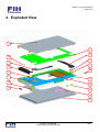
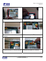
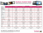
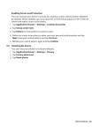
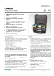
FM6 L1~L2 Service Manual Version 2.0 FM6 L1~L2 Service Manual FM6 L1~L2 Service Manual Version 2.0 Contents Revision.......................................................................................................................................................... 3 1. Specification.......................................................................................................................................... 4 2. General Introduction ........................................................................................................................... 6 3. Equipment.............................................................................................................................................. 7 4. Exploded View ...................................................................................................................................... 9 5. Disassembly ........................................................................................................................................ 11 6. Assembly.............................................................................................................................................. 16 Company Confidential Unauthorized Copy Not Allowed 2/20 FM6 L1~L2 Service Manual Version 2.0 Revision Date Version Comment 2010-07-09 1.0 Initial release of document TKPan 2010-07-13 2.0 Modify exploded view and spare part list Linda Company Confidential Unauthorized Copy Not Allowed Owner 3/20 FM6 L1~L2 Service Manual Version 2.0 1. Specification Feather Platform Specification Operating System Android Donut Dimension Size: 179.4 mm (H) x 110 mm (W) x 11.5 mm (T) Weight: 375g with battery pack Processor/Chipset Qualcomm MSM7227 (App: ARM11 600MHz) Memory ROM: 512 MB NAND Flash RAM: 512 MB DDR Display Size: 7” Type: TFT transmissive LCD Resolution: 800 x 480, WVGA Color: 16M; 24 bits, 65K color depth by Android OS Touch panel: Capacitive -type touch lens Radio Band & Standard GSM/GPRS/EDGE/UMTS/HSDPA GSM bands: 850/900/1800/1900 UMTS bands: 900/1900/2100 or 850/1900/2100 GPRS: GPRS Class 12 EGPRS/EDGE: Multi-Slot Class 12 UMTS: DL/UL, HSDPA 7.2Mbps Connectivity GPS/AGPS WiFi: 802.11b/g Bluetooth 2.1 + EDR USB 2.0 High-Speed client; and OTG mode Audio Built-in microphone and loudspeaker 3.5mm audio jack for stereo headset interface Advanced Echo Cancellation for phone Decoder: AAC LC/LTP, HE-AACv1 (AAC+), HE-AACv2 (enhanced AAC+), AMR-NB, AMR-WB, MP3, MIDI, Ogg Vorbis, PCM / WAVE Encoder: AMR-NB Video Video playback: H.263, H.264 AVC, MPEG-4 SP Picture Still image: JPEG, GIF, BMP, PNG Camera CMOS 3MP AF Company Confidential Unauthorized Copy Not Allowed 4/20 FM6 L1~L2 Service Manual Version 2.0 Interface mini-USB connector with data sync, power charging features MicroSD card slot Sensor G-sensor E-compass sensor Ambient light sensor Power Battery: – 3240 mAH with hard-packed Li-Polymer – Standby time: Up to 550 hours for WCDMA (TBD) Up to 400 hours for GSM (TBD) – Video playback : with external speakers (50% backlight and volume) (TBD) with headset (50% backlight) (TBD) – Internet browsing: via 3G (50% backlight) (TBD) via WiFi (50% backlight) (TBD) – Full charged time: less than 4 hours(TBD) AC adapter: – AC input voltage: 100~240 Vac, 50/60Hz – AC input current: 300mAac max. – DC output voltage: 5Vdc (typical) – DC output current: 2A (typical) Company Confidential Unauthorized Copy Not Allowed 5/20 FM6 L1~L2 Service Manual Version 2.0 2.General Introduction SD Card SIM Card Volume Key Power Key Microphone Reset Key Audio Jack USB Jack Company Confidential Unauthorized Copy Not Allowed 6/20 FM6 L1~L2 Service Manual Version 2.0 3. Equipment STANDARD TOOLS • Plastic plate • Screwdriver Phillips #00 cross-like head • Slotted screwdriver ESD EQUIPMENT Protect the phone from ESD damages whenever it has been opened by using: • ESD-wristband • ESD-gloves Company Confidential Unauthorized Copy Not Allowed 7/20 FM6 L1~L2 Service Manual Version 2.0 A screwdriver is needed to assemble/disassemble the FM6’ Case-A, Case-B, metal frame . We should use electrical screwdriver with Phillips #00 cross-like head. Please notice that the torque is 0.4 kg-cm. Electrical screwdriver with torque and rotation speed controller. Screws type list Color Part no. Spec. Length Screw DriverType W1101141520 M1.4 1.5 Ph00 Bright Nickel Flat Head W2101163520 M1.6 3.5 Ph00 Black Nickel Flat Head W5101143220 1.4 3.2 Ph00 Black Nickel Flat Head Screw Head / Body Company Confidential Unauthorized Copy Not Allowed 8/20 FM6 L1~L2 Service Manual Version 2.0 4. Exploded View 9 1 4 16 6 5 7 8 14 6 7 3 12 10 13 13 11 2 Company Confidential Unauthorized Copy Not Allowed 9/20 FM6 L1~L2 Service Manual Version 2.0 # Part Number Descripition Quantity 1 20FM60W001A ASSY KIT_FM6/PCBA_MB 1 2 20FM60W002A ASSY KIT_FM6/LTM_Module 1 3 20FM60W003A ASSY KIT_FM6/Metal Sideband 1 4 20FM60W004A ASSY KIT_FM6/ANT_BT/WIFI 1 5 20FM60W005A ASSY KIT_FM6/ANT_GPS 1 6 20FM60W006A ASSY KIT_FM6/Speaker 1 7 20FM60W007A ASSY KIT_FM6/Sponge Speaker 1 8 S0A306560A0 ANT_GSM_EU_71.2*15.21*7.55mm_Black 1 9 MEMR761002A Assy_Battery_Cover_MR7 1 10 S0C320A2040 CAM_3M AF QXGA_1/4"_MT9T112_DO-8012 1 11 MEMR771001A Cap_SIM_SD_MR7 1 12 MEMR707002A Key_Power_MR7 1 13 MEMR707001A Key_Volume_MR7 1 14 MEFM638002A Mesh_Speaker_Bottom_FM6 1 15 MEFM638001A Mesh_Speaker_Power_FM6 1 16 MEFM636001A Rubber_Mic_FM6 1 Company Confidential Unauthorized Copy Not Allowed 10/20 FM6 L1~L2 Service Manual Version 2.0 5. Disassembly 1. Open the sim cover and remove one screw 2. Remove the back cover. Start opening at top by Phillips #00 screwdriver. side. 3. Use plastic plate to open the back cover. 4. Remove the Power cable. 5. Remove the SIM cover 6. Remove one screw by PH#00 screwdriver. Company Confidential Unauthorized Copy Not Allowed 11/20 FM6 L1~L2 Service Manual Version 2.0 7. Pull out the BT antenna. 8. Remove GPS Antenna. 9. Use slotted screwdriver to remove main 10.Release two speaker FPC connectors. antenna. 11.Release Soft-Key FPC connector carefully. 12.Release touch-panel FPC connector. Company Confidential Unauthorized Copy Not Allowed 12/20 FM6 L1~L2 Service Manual Version 2.0 13.Release the SUB FPC BTB (Board to Board) 14.Remove the battery. connector. 15.Remove the Foil. 16.Release LCM FPC connector. 17.Remove the power key. 18.Remove three screws by Phillips #00 screwdriver. Company Confidential Unauthorized Copy Not Allowed 13/20 FM6 L1~L2 Service Manual Version 2.0 19.Use slotted screwdriver to pull the PCB 20.Pull up the PCB board carefully. board up. 21.Remove the volume key. 22.Remove the camera. 23.Use plastic plate to open the touch-panel 24.Remove the touch-panel from the LCM carefully, especially in FPC connector. Company Confidential Unauthorized Copy Not Allowed 14/20 FM6 L1~L2 Service Manual Version 2.0 25.Remove the LCM if necessary. Company Confidential Unauthorized Copy Not Allowed 15/20 FM6 L1~L2 Service Manual Version 2.0 6. Assembly 1. Assemble .Adhesive_LCM at the back of 2. Assemble LCM into housing. LCM. 3. Remove all liner on the touch panel. 4. Assemble touch panel into housing carefually, especially at two FPC. 5. Place Touch panel FPC and soft-key FPC in 6. Assemble Volume key in the volume key correct place. hole. Company Confidential Unauthorized Copy Not Allowed 16/20 FM6 L1~L2 Service Manual Version 2.0 7. Assemble Microphone rubber in the microphone hole. 8. Assemble PCB board carefully, especially in mark place. 9. Screw three screws at mark place by PH#00 10. Assemble Speaker FPC and Sponge screwdriver 11. Stick the conductive adhesive at LCM connector. 12.Connect the LCM FPC to LCM Connector Company Confidential Unauthorized Copy Not Allowed 17/20 FM6 L1~L2 Service Manual Version 2.0 13.Stick the LCM Mylar 14.Stick the LCM Foil d a 15.Assemble the camera in camera hole, according to the left & top side. b c 16.Connect Below FPC a. speaker FPC b. Touch panel FPC c. camera FPC d. Soft Key FPC 2 17.Assemble power key to power key hole. a 1 18.Assemble the main antenna. Company Confidential Unauthorized Copy Not Allowed 18/20 FM6 L1~L2 Service Manual Version 2.0 19.Assemble the GPS Antenna 20.Assemble the BT Antenna. 21.Screw at BT antenna as shown in figure. 22.Assemble the SIM Cover. 23.Place the battery 24.Connect the battery connector Company Confidential Unauthorized Copy Not Allowed 19/20 FM6 L1~L2 Service Manual Version 2.0 25.Assemble the back structure. 26.Stick the back_cover_adhesive. 27.Assemble the back cover 28.Screw at side structure as shown in figure. Company Confidential Unauthorized Copy Not Allowed 20/20