1
2.2
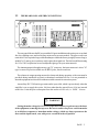
THE REAR PANEL AND THE CONNECTIONS
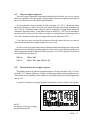
REMOTE CONTROL
0678
MADE IN ITALY
AUX-1A Max
RF OUT
RF IN
115/230V ac-50/60Hz
1400/2400 VA
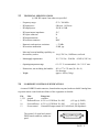
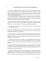
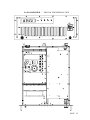
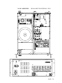
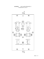
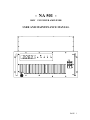
The rear panel allocates the RF power and the I/O ports in addition to the mains power cord and
fuse, the earthling screw and an auxiliary mains socket on some models. The power cord is not
removable. If it is required a longer cable than that provided in the factory (roughly 2 meters long), a
suitable 3x 1.5 mm sq. power cord may easily replace the original one. The fuse has a different rating
for 115 or 230Vac operation: be sure to adopt the right type for your mains network
The Antenna output is brought out on a type "N" connector, the input connector is also a "N"
type. A remote I/O port is available on a SUBD 25 poles, female connector.
The exhaust air output opening must not be obstructed during operation: wide room must be
provided during installation to permit a substained ventilation air flux. It is not permitted to
insert the equipment in a closed rack without a suitable external air extraction system.
An auxiliary IEC-320 female type mains outlet is provided, which is powered only when the
amplifier is on, to supply the exciter. No fuses other than the general fuses (16A) are inserted
on this line. Limit the power absorption from this outlet to low levels, i.e. 100W / 1A max.
,
WARNING !
Setting the mains voltage for 115 or 230V operation requires to gain access to the inner
of the equipment, removing the top cover. Be sure to remove the power cord from mains
to avoid direct exposure to hazardous mains voltage, which are always present on the
fuses and the input board, even with power on switch in the off position.
PAGE 5